ELC AL 936N User manual

MANUEL D'INSTRUCTIONS
INSTRUCTIONS MANUAL
BEDIENUNGSHANDBUCH
ALIMENTATION STABILISEE
STABILIZED POWER-SUPPLY
STABILISIERTES NETZGERÄT
2 x 0 - 30V 0 - 3A
2 - 5,5V 3A or 5,5V - 15V 1A
AL 936N
MANUEL D'INSTRUCTIONS
INSTRUCTIONS MANUAL
BEDIENUNGSHANDBUCH
ALIMENTATION STABILISEE
STABILIZED POWER-SUPPLY
STABILISIERTES NETZGERÄT
2 x 0 - 30V 0 - 3A
2 - 5,5V 3A or 5,5V - 15V 1A
AL 936N
- 2 -
- 2 -
4000 4 200_Rev1 - 12/09
4000 4 200_Rev1 - 12/09
I
UIU
DC POWER SUPPLY A - MASTER DC POWER SUPPLY B - SLAVE
REGULATION
REGULATION
0 - 30V 0 - 3A 0 - 30V 0 - 3A
AUXILIARY
Icc
DC POWER SUPPLY AL 936N
Icc
Voltage
Current
Display
Separate
Tracking
Series
Parallel
Standby
Series
0 - 60V
Parallel
0 - 6A
Series
Made i n FRANCE Series
fine fine
! ! !
++
--
+-
+-
+-
0
outputs
BA
A
BA
B
A
Mode 2 - 15V
O
I
I
UIU
DC POWER SUPPLY A - MASTER DC POWER SUPPLY B - SLAVE
REGULATION
REGULATION
0 - 30V 0 - 3A 0 - 30V 0 - 3A
AUXILIARY
Icc
DC POWER SUPPLY AL 936N
Icc
Voltage
Current
Display
Separate
Tracking
Series
Parallel
Standby
Series
0 - 60V
Parallel
0 - 6A
Series
Made i n FRANCE Series
fine fine
! ! !
++
--
+-
+-
+-
0
outputs
BA
A
BA
B
A
Mode 2 - 15V
O
I
3 2 1 33 32 31 30 29 28
20
12 13 14 15 16 18
17 19
24
22
21
25
23
27
26
8
5
6
7
4
9
10
11
3 2 1 33 32 31 30 29 28
20
12 13 14 15 16 18
17 19
24
22
21
25
23
27
26
8
5
6
7
4
9
10
11
34
34

- 3 -
- 3 -
4000 4 200_Rev1 - 12/094000 4 200_Rev1 - 12/09
FRANCAIS
TABLE DES MATIERES
1 RENSEIGNEMENTS PRELIMINAIRES page 3
2 DESCRIPTION page 3
2.1 PRESENTATION page 3
2.2 DESIGNATION FONCTIONNELLE DE L’APPAREIL page 3
2.3 COMPOSITION DE L’ENSEMBLE DE L’APPAREIL page 4
2.4 SYMBOLES ET DEFINITIONS page 4
2.5 CARACTERISTIQUES TECHNIQUES page 4
3 PRINCIPE DE FONCTIONNEMENT page 5
3.1 RAPPEL SUR LA CARACTERISTIQUE RECTANGULAIRE page 5
3.2 SYNOPTIQUES DES DIFFERENTS MODES page 5
4 INSTRUCTIONS PRELIMINAIRES page 7
4.1 DEBALLAGE ET REMBALLAGE page 7
4.2 MONTAGE ET MISE EN PLACE DE L’APPAREIL page 7
5 PREPARATION AU FONCTIONNEMENT page 7
6 INSTRUCTIONS POUR L’UTILISATION page 7
6.1 PRESCRIPTIONS DE SECURITE page 7
6.2 ORGANES DE COMMANDE page 7
6.3 PREPARATION POUR LES MESURES page 9
6.4 APPLICATIONS page 10
7 MAINTENANCE page 10
8 SERVICE APRES VENTE page 10
9 DECLARATION DE CONFORMITE page 10
1. RENSEIGNEMENTS PRELIMINAIRES
Constructeur : elc 59 avenue des Romains 74000 ANNECY - FRANCE
Téléphone : +33 (0)4 50 57 30 46 Fax : +33 (0)4 50 57 45 19
Instrument : ALIMENTATION STABILISEE
Marque : elc
Type : AL 936N
2. DESCRIPTION
2.1 PRESENTATION
Vous venez d’acquérir l’ALIMENTATION STABILISEE type elcAL936N. Nous vous
en remercions et vous félicitons de votre choix.
elc c’est toute une gamme d’Alimentations mais aussi de nombreux appareils
électroniques : GENERATEURS BF, FREQUENCEMETRES, APPAREILS DE TABLEAU...
Cet appareil a été construit conformément à la norme européenne EN 61010-1 et a
étéfournienbonétat.Cet appareil électrique est destiné auxusagesprofessionnels,
industriels et éducatifs. Le présent manuel d’instruction contient des textes
d’informations et d’avertissements qui doivent être respectés par l’acheteur pour
assurer un fonctionnement sûr et pour maintenir l’appareil en bon état.
2.2 DESIGNATION FONCTIONNELLE DE L’APPAREIL
Cet appareil pratique, utilisable en laboratoire, vous donnera satisfaction en vous
offrant plusieurs possibilités.
Trois alimentations indépendantes réguléesen tension et encourantcomposentcet
appareil :
Deux alimentations (A - Master et B - Slave) délivrent chacune en sortie 0 à 30V et
0 à 3A. Elles peuvent être couplées suivant 4 modes de fonctionnement :
Separated : 2 x 0 à 30V et 0 à 3A
Tracking : ± 0 à 30V et 0 à 3A
Series : 0 à 60V et 0 à 3A
Parallèle : 0 à 30V et 0 à 6A
De plus une activation du mode Standby connecte les bornes de sortie des
alimentations. Le mode Standby est automatique dès qu’une sélection de mode est
effectuée.
Les tensions et courants de sortie sont affichés par des voltmètres et ampèremètres
numériques de 3 digits.
Utiliséeconjointementavecleréglagedu courant, la sélection du court-circuit Icc,en
modeStandbyseulement,permetde régler l’intensité maximaledes2alimentations.
Une alimentation "Auxiliary" avec 2 modes d'affichage:
2 à 5,5V - 3A : La tension est variable, le courant est de 3A
5,5V à 15V - 1A : La tension est variable, le courant est de 1A
La tension ou le courant de sortie de l’alimentation est affichée, au choix, par un
indicateur à 3 digits.

- 4 -
- 4 -
4000 4 200_Rev1 - 12/09
4000 4 200_Rev1 - 12/09
2.3 COMPOSITION DE L’ENSEMBLE DE L’APPAREIL
VotrealimentationAL936N vous est livréeavecsoncordon secteur fiche «EUROPE»
2 pôles + terre et son manuel d’instructions.
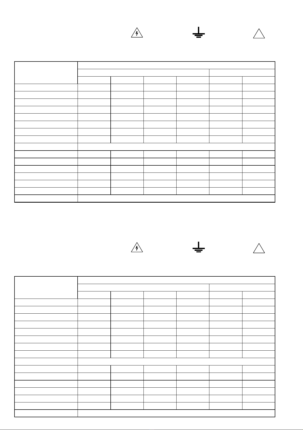
2.4 SYMBOLES ET DEFINITION
Vous trouverez les symboles ci-après sur le matériel :
2.5 CARACTERISTIQUESTECHNIQUES À 230V ET 23°C
FRANCAIS
FRANCAIS
SELECTION DES MODES DE FONCTIONNEMENT
ALIMENTATIONS MAITRE ET ESCLAVE ALIMENTATION AUXILIAIRE
Séparé Symétrique Série Parallèle Variable Variable
T e n s i o n d e s o r t i e 0 à 30V 0 à 30V 0 à 60V 0 à 30V 2V à 5,5V 5,5V à 15V
Valeur minimale 0 à ± 10mV 0 à ± 10mV 0 à ± 20mV 0 à ± 10mV < 2V -
Ondulation résiduelle 1mV 1mV 1mV 1mV 1mV 1mV
Régulation pour charge de 0 à 100% 12mV 12mV 50mV 24mV 12mV 10mV
Régulation pour secteur de -6 à +7% 5mV 5mV 5mV 5mV 5mV 1mV
Résistance interne 4mΩ4mΩ16mΩ4mΩ4
mΩ4mΩ
Temps de réponse charge de 10 à 90% 30µs 30µs 30µs 30µs 100µs 60µs
Résolution de l'Affichage 100mV 100mV 100mV 100mV 10mV 100mV
Lecture Voltmètre numérique de 3 digits de 14mm
C o u r a n t d e s o r t i e 0 à 3A 0 à 3A 0 à 3A 0 à 6A 3A 1A
Valeur minimale 10mA 10mA 10mA 20mA - -
Ondulation résiduelle 1mA 1mA 1mA 4mA - -
Régulation pour charge de 0 à 100% 2mA 2mA 4mA 8mA - -
Régulation pour secteur de -6 à +7% 1mA 1mA 1mA 5mA - -
Résolution de l'Affichage 10mA 10mA 10mA 10mA 10mA 10mA
Lecture Ampèremètre numérique de 3 digits de 14mm
CARACTERISTIQUES
TECHNIQUES
ATTENTION RISQUE DE
CHOC ELECTRIQUE
BORNE DE TERRE
FONCTIONNELLE
ATTENTION SE REFERER
AU MANUEL
!
ATTENTION RISQUE DE
CHOC ELECTRIQUE
BORNE DE TERRE
FONCTIONNELLE
ATTENTION SE REFERER
AU MANUEL
2.3 COMPOSITION DE L’ENSEMBLE DE L’APPAREIL
VotrealimentationAL936N vous est livréeavecsoncordon secteur fiche «EUROPE»
2 pôles + terre et son manuel d’instructions.
2.4 SYMBOLES ET DEFINITION
Vous trouverez les symboles ci-après sur le matériel :
2.5 CARACTERISTIQUESTECHNIQUES À 230V ET 23°C
!
SELECTION DES MODES DE FONCTIONNEMENT
ALIMENTATIONS MAITRE ET ESCLAVE ALIMENTATION AUXILIAIRE
Séparé Symétrique Série Parallèle Variable Variable
T e n s i o n d e s o r t i e 0 à 30V 0 à 30V 0 à 60V 0 à 30V 2V à 5,5V 5,5V à 15V
Valeur minimale 0 à ± 10mV 0 à ± 10mV 0 à ± 20mV 0 à ± 10mV < 2V -
Ondulation résiduelle 1mV 1mV 1mV 1mV 1mV 1mV
Régulation pour charge de 0 à 100% 12mV 12mV 50mV 24mV 12mV 10mV
Régulation pour secteur de -6 à +7% 5mV 5mV 5mV 5mV 5mV 1mV
Résistance interne 4mΩ4mΩ16mΩ4mΩ4
mΩ4mΩ
Temps de réponse charge de 10 à 90% 30µs 30µs 30µs 30µs 100µs 60µs
Résolution de l'Affichage 100mV 100mV 100mV 100mV 10mV 100mV
Lecture Voltmètre numérique de 3 digits de 14mm
C o u r a n t d e s o r t i e 0 à 3A 0 à 3A 0 à 3A 0 à 6A 3A 1A
Valeur minimale 10mA 10mA 10mA 20mA - -
Ondulation résiduelle 1mA 1mA 1mA 4mA - -
Régulation pour charge de 0 à 100% 2mA 2mA 4mA 8mA - -
Régulation pour secteur de -6 à +7% 1mA 1mA 1mA 5mA - -
Résolution de l'Affichage 10mA 10mA 10mA 10mA 10mA 10mA
Lecture Ampèremètre numérique de 3 digits de 14mm
CARACTERISTIQUES
TECHNIQUES
- 5 -
- 5 -
4000 4 200_Rev1 - 12/094000 4 200_Rev1 - 12/09
AUTRES CARACTERISTIQUES
Alimentation : Secteur 230V ±10% 50 / 60Hz
Entrée secteur : Embase «EUROPE» CEE 22 avec cordon 2 pôles + terre
Mise sous tension : Inter bipolaire
Sorties : Bornes de sécurité, norme VDE 0110
Consommation : 430VA
Rigidité diélectrique : 2300VAC entre entrée et sortie
2300VAC entre entrée et châssis
350VAC entre sortie et châssis
Dimensions : L=285mm H=151mm P=225mm
Présentation : Façade polycarbonate sérigraphiée
Habillage époxy texturé
Masse : 6,8kg
Condition d’utilisation : +5°C à 40°C
Condition de stockage : -10°C à 50°C
Condition d’humidité : Voir figure.
PROTECTIONS
Classe de sécurité : I
Contre les court-circuits, par limitation de courant.
Contre les échauffements excessifs :
- par ventilation asservie en température,
- par disjoncteur thermique incorporé dans le transformateur,
- par relais commutant les secondaires du transformateur.
Contre toute surintensité sur le transformateur,
- par fusible T3.15A 5x20 sur le primaire (accessible à l'arrière de l'appareil),
- par fusible F5A 5x20 sur les secondaires (à l'intérieur de l'appareil).
NORMES
CEM : EN 55011 groupe 1 - classe B
EN 50082-1 Critère d’aptitude A
SECURITE: EN 61010-1, catégorie de surtension ll et degré de pollution 2.
EN 61558-2-4, classe II sur le transformateur.
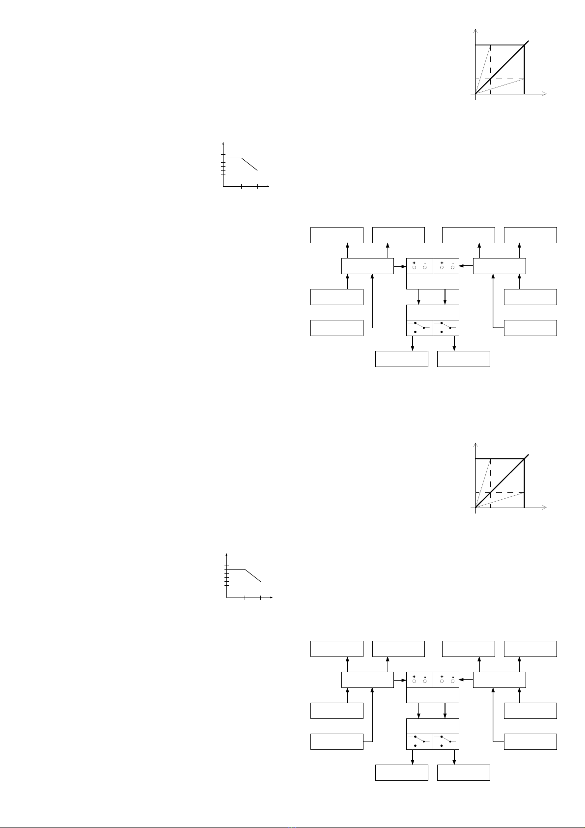
3. PRINCIPE DE FONCTIONNEMENT
3.1 RAPPEL SUR LA CARACTERISTIQUE RECTANGULAIRE
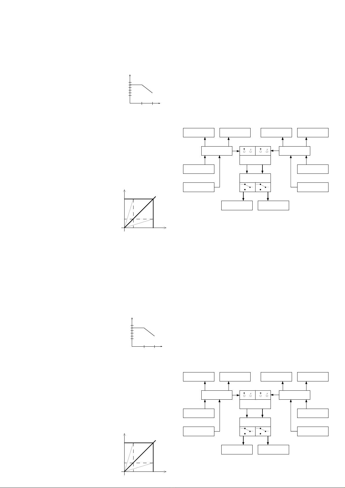
Une alimentation pouvant fonctionner à tension constante ou à courant constant est
dite à caractéristique rectangulaire (Fig. 1).
Le passage du fonctionnement «tension constante» au fonctionnement «courant
constant» est automatique en fonction des réglages de Vs et de Is et de la charge
appliquée à la sortie.
Si la résistance de charge RL est supérieure au rapport Vs/Is, l’alimentation
fonctionne à tension constante pour la valeur de la
tensiondesortiesélectionnée et avecunelimitation
de courant à Is.
Si RL varie de l’infini à Vs/Is, I peut varier de 0 à Is
(exemple I1) et la tension de sortie est constante.
Ainsi, pour que l’alimentation fonctionne à tension
constante, il importe que le courant de sortie soit
inférieur au courant limite sélectionné.
Dans le cas contraire, l’alimentation change de
fonctionnement et passe à courant constant.
Si la résistance de charge RL est inférieur au
rapport Vs/Is, l’alimentation fonctionne à courant constant, pour une valeur de
courant sélectionnée et avec une limitation de tension à Vs. Si RL varie de 0 à Vs/
Is, V peut varier de 0 à Vs et Is = constant (exemple V1).
Ainsi pour que l’alimentation fonctionne à courant constant, il faut que le réglage de
latensiondesortiesoitau maximum des valeurs spécifiées; fixerlecourantlimitepar
le réglage approprié en agissant sur la fonction Icc.
Attention,lorsquelesréglagesde tension etdecourantlimitesde sortie sont telsque
larésistancedechargeest égale au rapport Vs/Is,celapeutprovoqueruneinstabilité
de fonctionnement.
3.2 SYNOPTIQUES DES DIFFERENTS MODES
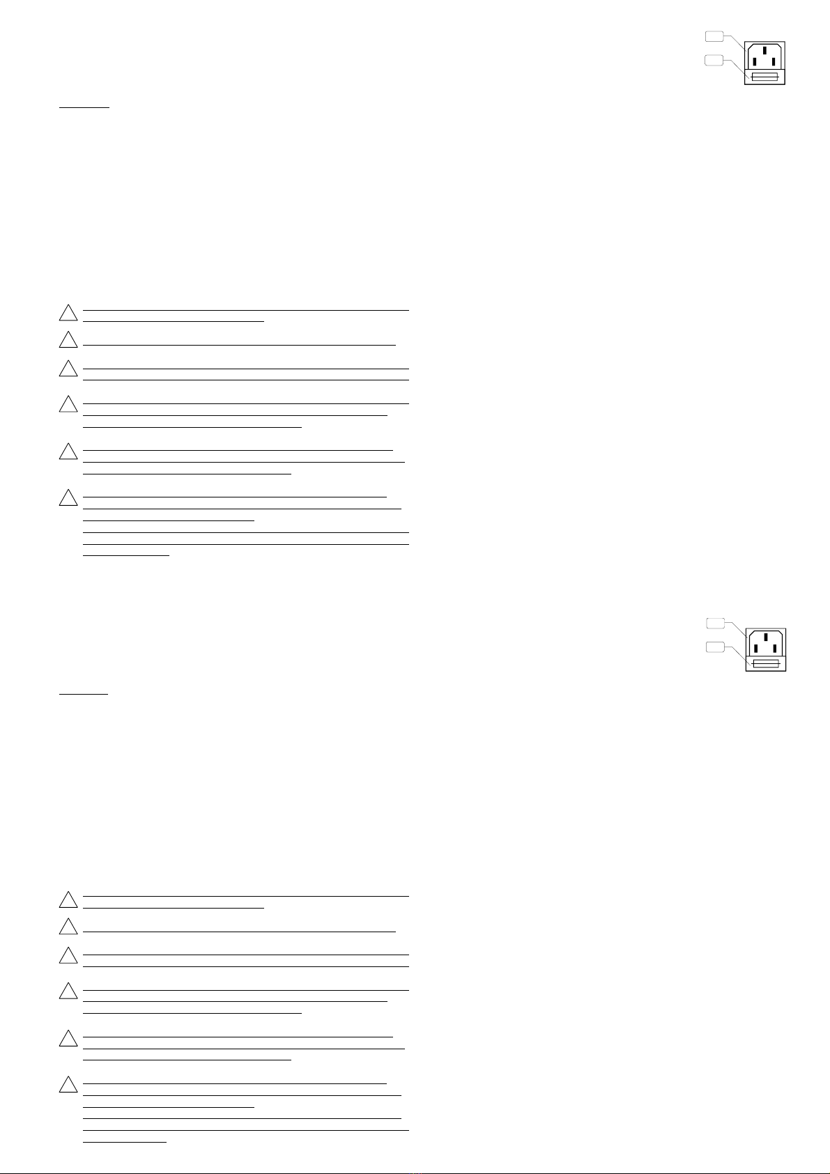
3.2.1 Mode "Separated"
Les2alimentationssontindépendantes et délivrent chacune unetensionréglablede
0 à 30V et un courant réglable de 0 à 3A.
FRANCAIS
Affichage de la tension Affichage du courant Affichage de la tension Affichage du courant
Puissance MAITRE Puissance ESCLAVE
Mode SEPARATED
Régulation de courant Régulation de courant
Mode STANDBY
Régulation de tension Régulation de tension
Sortie MAITRE Sortie ESCLAVE
3.2.2 Mode "Tracking"
Cemodepermetdedélivrer2 tensions symétriques par rapport au pointmilieuformé
FRANCAIS
RL=Vs/Is
RL>Vs/Is
V
Vs
V1
Fig.1
RL>Vs/Is
I1 Is I
AUTRES CARACTERISTIQUES
Alimentation : Secteur 230V ±10% 50 / 60Hz
Entrée secteur : Embase «EUROPE» CEE 22 avec cordon 2 pôles + terre
Mise sous tension : Inter bipolaire
Sorties : Bornes de sécurité, norme VDE 0110
Consommation : 430VA
Rigidité diélectrique : 2300VAC entre entrée et sortie
2300VAC entre entrée et châssis
350VAC entre sortie et châssis
Dimensions : L=285mm H=151mm P=225mm
Présentation : Façade polycarbonate sérigraphiée
Habillage époxy texturé
Masse : 6,8kg
Condition d’utilisation : +5°C à 40°C
Condition de stockage : -10°C à 50°C
Condition d’humidité : Voir figure.
PROTECTIONS
Classe de sécurité : I
Contre les court-circuits, par limitation de courant.
Contre les échauffements excessifs :
- par ventilation asservie en température,
- par disjoncteur thermique incorporé dans le transformateur,
- par relais commutant les secondaires du transformateur.
Contre toute surintensité sur le transformateur,
- par fusible T3.15A 5x20 sur le primaire (accessible à l'arrière de l'appareil),
- par fusible F5A 5x20 sur les secondaires (à l'intérieur de l'appareil).
NORMES
CEM : EN 55011 groupe 1 - classe B
EN 50082-1 Critère d’aptitude A
SECURITE: EN 61010-1, catégorie de surtension ll et degré de pollution 2.
EN 61558-2-4, classe II sur le transformateur.
3. PRINCIPE DE FONCTIONNEMENT
3.1 RAPPEL SUR LA CARACTERISTIQUE RECTANGULAIRE
Une alimentation pouvant fonctionner à tension constante ou à courant constant est
dite à caractéristique rectangulaire (Fig. 1).
Le passage du fonctionnement «tension constante» au fonctionnement «courant
constant» est automatique en fonction des réglages de Vs et de Is et de la charge
appliquée à la sortie.
Si la résistance de charge RL est supérieure au rapport Vs/Is, l’alimentation
fonctionne à tension constante pour la valeur de la
tensiondesortiesélectionnée et avecunelimitation
de courant à Is.
Si RL varie de l’infini à Vs/Is, I peut varier de 0 à Is
(exemple I1) et la tension de sortie est constante.
Ainsi, pour que l’alimentation fonctionne à tension
constante, il importe que le courant de sortie soit
inférieur au courant limite sélectionné.
Dans le cas contraire, l’alimentation change de
fonctionnement et passe à courant constant.
Si la résistance de charge RL est inférieur au
rapport Vs/Is, l’alimentation fonctionne à courant constant, pour une valeur de
courant sélectionnée et avec une limitation de tension à Vs. Si RL varie de 0 à Vs/
Is, V peut varier de 0 à Vs et Is = constant (exemple V1).
Ainsi pour que l’alimentation fonctionne à courant constant, il faut que le réglage de
latensiondesortiesoitau maximum des valeurs spécifiées; fixerlecourantlimitepar
le réglage approprié en agissant sur la fonction Icc.
Attention,lorsquelesréglagesde tension etdecourantlimitesde sortie sont telsque
larésistancedechargeest égale au rapport Vs/Is,celapeutprovoqueruneinstabilité
de fonctionnement.
3.2 SYNOPTIQUES DES DIFFERENTS MODES
3.2.1 Mode "Separated"
Les2alimentationssontindépendantes et délivrent chacune unetensionréglablede
0 à 30V et un courant réglable de 0 à 3A.
Affichage de la tension Affichage du courant Affichage de la tension Affichage du courant
Puissance MAITRE Puissance ESCLAVE
Mode SEPARATED
Régulation de courant Régulation de courant
Mode STANDBY
Régulation de tension Régulation de tension
Sortie MAITRE Sortie ESCLAVE
3.2.2 Mode "Tracking"
Cemodepermetdedélivrer2 tensions symétriques par rapport au pointmilieuformé
RL=Vs/Is
RL>Vs/Is
V
Vs
V1
Fig.1
RL>Vs/Is
I1 Is I
8 0
5 0
3 1 4 0 °
C
%
h u m i d i t é r e l a t i v e
m a x i m a l e
8 0
5 0
3 1 4 0 °
C
%
h u m i d i t é r e l a t i v e
m a x i m a l e

- 6 -
- 6 -
4000 4 200_Rev1 - 12/09
4000 4 200_Rev1 - 12/09
delabornenégativede l’alimentation maître «A»etlabornepositive de l’alimentation
esclave «B». La régulation de tension de l’esclave «B» est commandée par celle de
la maître «A». Le réglage du courant reste indépendant et ajustable de 0 à 3A pour
chaque alimentation.
Affichage de la tension Affichage du courant
Puissance MAITRE Puissance ESCLAVE
Mode SERIES
Régulation de courant
Mode SERIES
Régulation de tension
Sortie MAITRE Sortie ESCLAVE
Affichage de la tension Affichage du courant
Puissance MAITRE Puissance ESCLAVE
Mode PARALLEL
Régulation de courant
Mode STANDBY
Régulation de tension
Sortie MAITRE (+)
3.2.4 Mode "Parallel"
Il permet d’obtenir une alimentation réglable de 0 à 30V avec un courant de 0 à 6A.
Les régulations de tension et de courant de l’esclave «B» sont pilotées depuis le
maître «A», l’affichage des grandeurs s’effectuant sur l’alimentation maître.
3.2.5 Modes de l’alimentation auxiliaire "AUXILIARY".
Deux modes de fonctionnement sont possibles :
- 2 à 5.5V -3A l’alimentation auxiliaire est réglable de moins de 2V à 5.5V et
délivre un courant de 3A.
- 5.5V à 15V -1A l’alimentation délivre une tension de 5.5V à 15V avec un
courant de 1A.
La tension est affichée avec une résolution de 10mVen mode 2 à5.5V et de100mV
en mode 5.5V à 15V.
FRANCAIS
FRANCAIS
MODE AUXILIARY
Affichage du
Variable
2 à 5.5V 3A
courant
Régulation de tension
Affichage de
la tension
Régulation de courant Variable 5.5V - 15V
1A
Puissance
Sortie
Affichage de la tension Affichage du courant Affichage de la tension Affichage du courant
Puissance MAITRE Puissance ESCLAVE
Mode TRACKING
Régulation de courant Régulation de courant
Mode STANDBY
Régulation de tension
Sortie MAITRE Sortie ESCLAVE
3.2.3 Mode "Series"
Il permet d’obtenir une alimentation réglable de 0 à 60V avec un courant de 0 à 3A.
Les régulations de tension et de courant de l’alimentation esclave «B» sont pilotées
depuislamaître«A».L’affichage des grandeurs s’effectuantsurl’alimentationmaître.
delabornenégativede l’alimentation maître «A»etlabornepositive de l’alimentation
esclave «B». La régulation de tension de l’esclave «B» est commandée par celle de
la maître «A». Le réglage du courant reste indépendant et ajustable de 0 à 3A pour
chaque alimentation.
Affichage de la tension Affichage du courant
Puissance MAITRE Puissance ESCLAVE
Mode SERIES
Régulation de courant
Mode SERIES
Régulation de tension
Sortie MAITRE Sortie ESCLAVE
3.2.4 Mode "Parallel"
Il permet d’obtenir une alimentation réglable de 0 à 30V avec un courant de 0 à 6A.
Les régulations de tension et de courant de l’esclave «B» sont pilotées depuis le
maître «A», l’affichage des grandeurs s’effectuant sur l’alimentation maître.
3.2.5 Modes de l’alimentation auxiliaire "AUXILIARY".
Deux modes de fonctionnement sont possibles :
- 2 à 5.5V -3A l’alimentation auxiliaire est réglable de moins de 2V à 5.5V et
délivre un courant de 3A.
- 5.5V à 15V -1A l’alimentation délivre une tension de 5.5V à 15V avec un
courant de 1A.
La tension est affichée avec une résolution de 10mVen mode 2 à5.5V et de100mV
en mode 5.5V à 15V.
MODE AUXILIARY
Affichage du
Variable
2 à 5.5V 3A
courant
Régulation de tension
Affichage de
la tension
Régulation de courant Variable 5.5V - 15V
1A
Puissance
Sortie
Affichage de la tension Affichage du courant Affichage de la tension Affichage du courant
Puissance MAITRE Puissance ESCLAVE
Mode TRACKING
Régulation de courant Régulation de courant
Mode STANDBY
Régulation de tension
Sortie MAITRE Sortie ESCLAVE
3.2.3 Mode "Series"
Il permet d’obtenir une alimentation réglable de 0 à 60V avec un courant de 0 à 3A.
Les régulations de tension et de courant de l’alimentation esclave «B» sont pilotées
depuislamaître«A».L’affichage des grandeurs s’effectuantsurl’alimentationmaître.
Affichage de la tension Affichage du courant
Puissance MAITRE Puissance ESCLAVE
Mode PARALLEL
Régulation de courant
Mode STANDBY
Régulation de tension
Sortie MAITRE (+)

- 7 -
- 7 -
4000 4 200_Rev1 - 12/094000 4 200_Rev1 - 12/09
4. INSTRUCTIONS PRELIMINAIRES
4.1 DEBALLAGE ET REMBALLAGE
L’alimentation lors de son transport, est protégée par du «Bull-pack» dans un
emballage cartonné afin d’éviter tous dommages.
Conservez-les ils pourront être utiles ultérieurement.
Liste de colisage :
1 manuel d’instruction 1 «Bull-pack» 1 enrobage en carton
1 Alimentation : AL 936N 1 cale en carton 1 Cordon secteur
4.2 MONTAGE ET MISE EN PLACE DE L’APPAREIL
Pour une bonne convection naturelle, l’alimentation doit reposer sur ses 4 butées
caoutchouc et toutes les ouvertures d’aération doivent être largement dégagées.
Brancherlecordon secteur dansl’embase«EUROPE» CEE22 àl’arrièrede l’appareil.
5. PREPARATION AU FONCTIONNEMENT
Raccorder l’alimentation au réseau 230V et mettre sous tension avec l’interrupteur
Marche/Arrêt.
6. INSTRUCTION POUR L’UTILISATION
6.1 PRESCRIPTION DE SECURITE
Touteinterventionàl’intérieur de l’appareil etparticulièrementleremplacement
des fusibles doivent être effectués par du personnel qualifié.
L’appareil doit être utilisé conformément aux instructions de ce document.
Lapriseducordonsecteurétant utilisée comme le dispositif desectionnement,
l’appareildoitêtreraccordésur un socle de priseaisémentaccessibleetdevant
comporter la terre.
Lorsquecetappareildoitêtre alimentéparl’intermédiaire d’unautotransformateur
séparé en vue d’une réduction de la tension, veiller à ce que la borne commune
soit raccordée au pôle mis à la terre du circuit d’alimentation.
La tension de mode commun entre la terre et les bornes de sortie ne doit pas
dépasser 50V efficaces. Dans ce cas une tension jugée dangereuse (> 60Vdc)
peut être atteinte entre l’une des bornes et la terre.
En mode series ou tracking une tension de 60V jugée dangereuse peut être
disponibleentrelaborne + de l’alimentationMaîtreetlaborne - de l’alimentation
esclave.
Dans ces cas, il est impératif d’utiliser des cordons de sécurité pour le
raccordement aux sorties de l’appareil. De plus les appareils raccordés ne
doivent pas présenter de parties conductrices accessibles.
6.1.1 Description de la face arrière
AEMBASE SECTEUR
BFUSIBLE T3.15A
Le fusible (5x20mm T3.15A) peut être remplacé par un
fusible de même type et de mêmes caractéristiques.
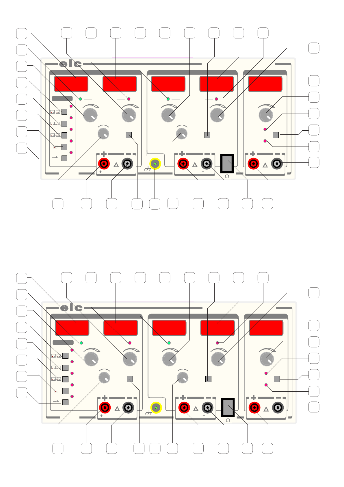
6.2 ORGANES DE COMMANDE
6.2.1 Vue d’ensemble de la face avant
1 AFFICHAGE DU COURANT
2 CONTROLE DE LA REGULATION DE COURANT
3 REGLAGE DU COURANT
4 AFFICHAGE DE LA TENSION
5 CONTROLE DE LA REGULATION DE TENSION
6 REGLAGE DE LA TENSION
7 SELECTION DU MODE "SEPARATED"
8 SELECTION DU MODE "TRACKING"
9 SELECTION DU MODE "SERIES"
10 SELECTION DU MODE "PARALLEL"
11 SELECTION DU MODE "STANDBY"
12 REGLAGE FIN DE LA TENSION
13 BORNE POSITIVE
14 BORNE NEGATIVE
15 SELECTION DU COURT-CIRCUIT
16 REGLAGE FIN DE LA TENSION
17 BORNE POSITIVE
18 BORNE NEGATIVE
19 INTERRUPTEUR MARCHE / ARRET
20 BORNE POSITIVE
21 BORNE NEGATIVE
22 MODE VOLTMETRE
23 SELECTION DU MODE VOLTMETRE/AMPEREMETRE
24 MODE AMPEREMETRE
25 REGLAGE DE LA TENSION
26 AFFICHAGE DE LA TENSION OU DU COURANT (CF 23)
27 REGLAGE DU COURANT
28 CONTROLE DE LA REGULATION DE COURANT
29 AFFICHAGE DU COURANT
30 SELECTION DU COURT-CIRCUIT
31 REGLAGE RAPIDE DE LA TENSION
32 AFFICHAGE DE LA TENSION
33 CONTROLE DE LA REGULATION DE TENSION
34 BORNE DE TERRE FONCTIONELLE
FRANCAIS
A
B
FRANCAIS
!
4. INSTRUCTIONS PRELIMINAIRES
4.1 DEBALLAGE ET REMBALLAGE
L’alimentation lors de son transport, est protégée par du «Bull-pack» dans un
emballage cartonné afin d’éviter tous dommages.
Conservez-les ils pourront être utiles ultérieurement.
Liste de colisage :
1 manuel d’instruction 1 «Bull-pack» 1 enrobage en carton
1 Alimentation : AL 936N 1 cale en carton 1 Cordon secteur
4.2 MONTAGE ET MISE EN PLACE DE L’APPAREIL
Pour une bonne convection naturelle, l’alimentation doit reposer sur ses 4 butées
caoutchouc et toutes les ouvertures d’aération doivent être largement dégagées.
Brancherlecordon secteur dansl’embase«EUROPE» CEE22 àl’arrièrede l’appareil.
5. PREPARATION AU FONCTIONNEMENT
Raccorder l’alimentation au réseau 230V et mettre sous tension avec l’interrupteur
Marche/Arrêt.
6. INSTRUCTION POUR L’UTILISATION
6.1 PRESCRIPTION DE SECURITE
Touteinterventionàl’intérieur de l’appareil etparticulièrementleremplacement
des fusibles doivent être effectués par du personnel qualifié.
L’appareil doit être utilisé conformément aux instructions de ce document.
Lapriseducordonsecteurétant utilisée comme le dispositif desectionnement,
l’appareildoitêtreraccordésur un socle de priseaisémentaccessibleetdevant
comporter la terre.
Lorsquecetappareildoitêtre alimentéparl’intermédiaire d’unautotransformateur
séparé en vue d’une réduction de la tension, veiller à ce que la borne commune
soit raccordée au pôle mis à la terre du circuit d’alimentation.
La tension de mode commun entre la terre et les bornes de sortie ne doit pas
dépasser 50V efficaces. Dans ce cas une tension jugée dangereuse (> 60Vdc)
peut être atteinte entre l’une des bornes et la terre.
En mode series ou tracking une tension de 60V jugée dangereuse peut être
disponibleentrelaborne + de l’alimentationMaîtreetlaborne - de l’alimentation
esclave.
Dans ces cas, il est impératif d’utiliser des cordons de sécurité pour le
raccordement aux sorties de l’appareil. De plus les appareils raccordés ne
doivent pas présenter de parties conductrices accessibles.
6.1.1 Description de la face arrière
AEMBASE SECTEUR
BFUSIBLE T3.15A
Le fusible (5x20mm T3.15A) peut être remplacé par un
fusible de même type et de mêmes caractéristiques.
6.2 ORGANES DE COMMANDE
6.2.1 Vue d’ensemble de la face avant
1 AFFICHAGE DU COURANT
2 CONTROLE DE LA REGULATION DE COURANT
3 REGLAGE DU COURANT
4 AFFICHAGE DE LA TENSION
5 CONTROLE DE LA REGULATION DE TENSION
6 REGLAGE DE LA TENSION
7 SELECTION DU MODE "SEPARATED"
8 SELECTION DU MODE "TRACKING"
9 SELECTION DU MODE "SERIES"
10 SELECTION DU MODE "PARALLEL"
11 SELECTION DU MODE "STANDBY"
12 REGLAGE FIN DE LA TENSION
13 BORNE POSITIVE
14 BORNE NEGATIVE
15 SELECTION DU COURT-CIRCUIT
16 REGLAGE FIN DE LA TENSION
17 BORNE POSITIVE
18 BORNE NEGATIVE
19 INTERRUPTEUR MARCHE / ARRET
20 BORNE POSITIVE
21 BORNE NEGATIVE
22 MODE VOLTMETRE
23 SELECTION DU MODE VOLTMETRE/AMPEREMETRE
24 MODE AMPEREMETRE
25 REGLAGE DE LA TENSION
26 AFFICHAGE DE LA TENSION OU DU COURANT (CF 23)
27 REGLAGE DU COURANT
28 CONTROLE DE LA REGULATION DE COURANT
29 AFFICHAGE DU COURANT
30 SELECTION DU COURT-CIRCUIT
31 REGLAGE RAPIDE DE LA TENSION
32 AFFICHAGE DE LA TENSION
33 CONTROLE DE LA REGULATION DE TENSION
34 BORNE DE TERRE FONCTIONELLE
A
B
!
!
!
!
!
!
!
!
!

- 8 -
- 8 -
4000 4 200_Rev1 - 12/09
4000 4 200_Rev1 - 12/09
6.2.2Définitiondesdifférentesfonctions
(19)
MARCHE - ARRET. Le repére O indique la position Arrêt de l’appareil.
(11)
SELECTION DU MODE STANDBY. En position attente LED rouge éclairée,
aucune tension n’est disponible sur les bornes de sortie des alimentations
Maître et Esclave. Une activation du mode attente connecte les bornes de
sortie et une nouvelle activation déconnecte celles-ci. De plus le mode
Standby est automatique dès qu’une sélection de mode est effectuée.
(34)
BORNE DE TERRE FONCTIONNELLE. Directement reliée à la terre par le
chassis. Permet de référencer votre montage à la terre. Cette connexion
n'est pas destinée à assurer la continuité du conducteur de protection.
MODE "SEPARATED" des alimentations A et B
(
7)
SELECTION DE MODE "SEPARATED"
Permet un fonctionnement indépendant des alimentations A et B.
(
6) (31)
REGLAGE DE LA TENSION
Permet d’ajuster une tension comprise entre 0 et 30V.
(12)(16)
REGLAGE FIN DE LA TENSION
Fait varier d’environ 2V la tension ajustée par
(6) (31)
.
(5) (33)
CONTROLE DE LA REGULATION DE TENSION
LaLEDverteéclairéenous indique que l’alimentationtravailleenrégulation
de tension.
(4) (32)
AFFICHAGE DE LA TENSION
Permet de lire la tension de 0 à 30V avec 100mV de résolution.
(3) (27)
REGLAGE DU COURANT
Permet d’ajuster un courant entre 0 et 3A
(15) (30)
SELECTION DU COURT-CIRCUIT
En mode standby seulement, utilisée conjoitement avec
(3)
(27)
, permet le
réglage du courant maximum de sortie.
(2) (28)
CONTROLE DE LA REGULATION DE COURANT
laLEDrougeéclairéenous indique que l’alimentationtravailleenrégulation
de courant.
(1) (29)
AFFICHAGE DU COURANT
Permet de lire le courant de 0 à 3A avec 10mA de résolution.
(13) (17)
BORNE POSITIVE
(14) (18)
BORNE NEGATIVE
Organes de l’alimentation A
: (1) (2) (3) (4) (5) (6) (12) (13) (14) (15)
Organes de l’alimentation B
: (16) (17) (18) (27) (28) (29) (30) (31) (32) (33)
MODE "TRACKING" des alimentations Master et Slave
(8)
SELECTION DU MODE "TRACKING"
Le mode "tracking" permet d’obtenir entre les bornes
(13)
(14)
et
(17)
(
18)
deux tensions identiques de 0 à 30V mais opposées.
(14)
(17)
BORNE NEGATIVE et BORNE POSITIVE
Ces bornes reliées en interne forment le point milieu de l’alimentation
symétrique.
(13)
BORNEPOSITIVE
(18)
BORNE NEGATIVE
(6)
REGLAGE DE LA TENSION
Permet d’ajuster symétriquement une tension entre 0 et 30V.
(12)
REGLAGE FIN DE TENSION
Fait varier symétriquement de 0 à 2V la tension ajustée par
(6)
.
(5) (33)
CONTROLE DE LA REGULATION DE TENSION
la LED verte éclairée nous indique que l’alimentation travaille en régulation
de tension.
(4) (32)
AFFICHAGE DE LA TENSION
Permet de lire la tension de 0 à 30V avec 100mV de résolution.
(3) (27)
REGLAGE DE COURANT
Permet d’ajuster un courant entre 0 et 3A.
(15) (30)
SELECTION DU COURT-CIRCUIT
En mode standby seulement, utilisée conjointement avec
(3) (27)
permet
le réglage du courant maximum de sortie.
(2)
(28)
CONTROLE DE LA REGULATION DE COURANT
LaLEDrougeéclairée nousindiquequel’alimentation travaille enrégulation
de courant.
(1)
(29)
AFFICHAGE DU COURANT
Permet de lire le courant de 0 à 3A avec 10mA de résolution.
ATTENTION
(16)
(31)
inhibés
MODE "SERIES" des alimentations Master et SLAVE
(
9)
SELECTION DU MODE "SERIES"
Le mode "series" des 2 alimentations permet d’obtenir sur les bornes
(13)
et
(18)
une tension de 0 à 60V, avec un courant de 0 à 3A.
(13)
BORNE POSITIVE
(18)
BORNE NEGATIVE
(6)
REGLAGE DE LA TENSION
Permet d’ajuster une tension comprise entre 0 et 60 Volts.
(12)
REGLAGE FIN DE TENSION
Fait varier symétriquement d'environ 4V la tension ajustée par
(6)
.
(5)
CONTROLE DE LA REGULATION DE TENSION
LaLEDverteéclairéenous indique que l’alimentationtravailleenrégulation
de tension.
(4)
AFFICHAGE DE LA TENSION
Permet de lire la tension de 0 à 60V avec 100mV de résolution.
(3)
REGLAGE DE COURANT
Permet d’ajuster un courant entre 0 et 3A.
(15)
SELECTION DU COURT-CIRCUIT
En mode standby seulement, utilisée conjointement avec
(3)
permet le
réglage du courant maximum de sortie.
(2)
CONTROLE DE LA REGULATION DE COURANT
LaLEDrougeéclairée nousindiquequel’alimentation travaille enrégulation
de courant.
FRANCAIS
FRANCAIS
6.2.2 Définition des différentes fonctions
(19)
MARCHE - ARRET. Le repére O indique la position Arrêt de l’appareil.
(11)
SELECTION DU MODE STANDBY. En position attente LED rouge éclairée,
aucune tension n’est disponible sur les bornes de sortie des alimentations
Maître et Esclave. Une activation du mode attente connecte les bornes de
sortie et une nouvelle activation déconnecte celles-ci. De plus le mode
Standby est automatique dès qu’une sélection de mode est effectuée.
(34)
BORNE DE TERRE FONCTIONNELLE. Directement reliée à la terre par le
chassis. Permet de référencer votre montage à la terre. Cette connexion
n'est pas destinée à assurer la continuité du conducteur de protection.
MODE "SEPARATED" des alimentations A et B
(
7)
SELECTION DE MODE "SEPARATED"
Permet un fonctionnement indépendant des alimentations A et B.
(
6) (31)
REGLAGE DE LA TENSION
Permet d’ajuster une tension comprise entre 0 et 30V.
(12)(16)
REGLAGE FIN DE LA TENSION
Fait varier d’environ 2V la tension ajustée par
(6) (31)
.
(5) (33)
CONTROLE DE LA REGULATION DE TENSION
LaLEDverteéclairéenous indique que l’alimentationtravailleenrégulation
de tension.
(4) (32)
AFFICHAGE DE LA TENSION
Permet de lire la tension de 0 à 30V avec 100mV de résolution.
(3) (27)
REGLAGE DU COURANT
Permet d’ajuster un courant entre 0 et 3A
(15) (30)
SELECTION DU COURT-CIRCUIT
En mode standby seulement, utilisée conjoitement avec
(3)
(27)
, permet le
réglage du courant maximum de sortie.
(2) (28)
CONTROLE DE LA REGULATION DE COURANT
laLEDrougeéclairéenous indique que l’alimentationtravailleenrégulation
de courant.
(1) (29)
AFFICHAGE DU COURANT
Permet de lire le courant de 0 à 3A avec 10mA de résolution.
(13) (17)
BORNE POSITIVE
(14) (18)
BORNE NEGATIVE
Organes de l’alimentation A
: (1) (2) (3) (4) (5) (6) (12) (13) (14) (15)
Organes de l’alimentation B
: (16) (17) (18) (27) (28) (29) (30) (31) (32) (33)
MODE "TRACKING" des alimentations Master et Slave
(8)
SELECTION DU MODE "TRACKING"
Le mode "tracking" permet d’obtenir entre les bornes
(13)
(14)
et
(17)
(
18)
deux tensions identiques de 0 à 30V mais opposées.
(14)
(17)
BORNE NEGATIVE et BORNE POSITIVE
Ces bornes reliées en interne forment le point milieu de l’alimentation
symétrique.
(13)
BORNE POSITIVE
(18)
BORNE NEGATIVE
(6)
REGLAGE DE LA TENSION
Permet d’ajuster symétriquement une tension entre 0 et 30V.
(12)
REGLAGE FIN DE TENSION
Fait varier symétriquement de 0 à 2V la tension ajustée par
(6)
.
(5) (33)
CONTROLE DE LA REGULATION DE TENSION
la LED verte éclairée nous indique que l’alimentation travaille en régulation
de tension.
(4) (32)
AFFICHAGE DE LA TENSION
Permet de lire la tension de 0 à 30V avec 100mV de résolution.
(3) (27)
REGLAGE DE COURANT
Permet d’ajuster un courant entre 0 et 3A.
(15) (30)
SELECTION DU COURT-CIRCUIT
En mode standby seulement, utilisée conjointement avec
(3) (27)
permet
le réglage du courant maximum de sortie.
(2)
(28)
CONTROLE DE LA REGULATION DE COURANT
LaLEDrougeéclairée nousindiquequel’alimentation travaille enrégulation
de courant.
(1)
(29)
AFFICHAGE DU COURANT
Permet de lire le courant de 0 à 3A avec 10mA de résolution.
ATTENTION
(16)
(31)
inhibés
MODE "SERIES" des alimentations Master et SLAVE
(
9)
SELECTION DU MODE "SERIES"
Le mode "series" des 2 alimentations permet d’obtenir sur les bornes
(13)
et
(18)
une tension de 0 à 60V, avec un courant de 0 à 3A.
(13)
BORNE POSITIVE
(18)
BORNE NEGATIVE
(6)
REGLAGE DE LA TENSION
Permet d’ajuster une tension comprise entre 0 et 60 Volts.
(12)
REGLAGE FIN DE TENSION
Fait varier symétriquement d'environ 4V la tension ajustée par
(6)
.
(5)
CONTROLE DE LA REGULATION DE TENSION
LaLEDverteéclairéenous indique que l’alimentationtravailleenrégulation
de tension.
(4)
AFFICHAGE DE LA TENSION
Permet de lire la tension de 0 à 60V avec 100mV de résolution.
(3)
REGLAGE DE COURANT
Permet d’ajuster un courant entre 0 et 3A.
(15)
SELECTION DU COURT-CIRCUIT
En mode standby seulement, utilisée conjointement avec
(3)
permet le
réglage du courant maximum de sortie.
(2)
CONTROLE DE LA REGULATION DE COURANT
LaLEDrougeéclairée nousindiquequel’alimentation travaille enrégulation
de courant.

- 9 -
- 9 -
4000 4 200_Rev1 - 12/094000 4 200_Rev1 - 12/09
(1) AFFICHAGE DU COURANT
Permet de lire le courant de 0 à 3A avec 10mA de résolution.
ATTENTION (14) (16) (17) (27) (28) (29) (30) (31) (32) (33) inhibés
MODE "PARALLEL" des alimentations Master et Slave
(10) SELECTION DU MODE "PARALLEL"
Le mode "parallel" des 2 alimentations permet d’obtenir entre les bornes
(13) et (14) une tension de sortie réglable de 0 à 30V, avec un courant
réglable de 0 à 6A.
(13) BORNE POSITIVE
(14) BORNE NEGATIVE
(6) REGLAGE DE LA TENSION
Permet d’ajuster une tension comprise entre 0 et 30 Volts.
(12) REGLAGE FIN DE TENSION
Fait varier de 0 à 2V la tension ajustée par (6).
(5) CONTROLE DE LA REGULATION DE TENSION
La LED verte éclairée nous indique que l’alimentation travaille en
régulation de tension.
(4) AFFICHAGE DE LA TENSION
Permet de lire la tension de 0 à 30V avec 100mV de résolution.
(3) REGLAGE DE COURANT
Permet d’ajuster un courant entre 0 et 6A.
(15) SELECTION DU COURT-CIRCUIT
En mode standby seulement, utilisée conjointement avec (3) permet le
réglage du courant maximum de sortie.
(2) CONTROLE DE LA REGULATION DE COURANT
La LED rouge éclairée nous indique que l’alimentation travaille en
régulation de courant.
(1) AFFICHAGE DU COURANT
Permet de lire le courant de 0 à 6A avec 10mA de résolution.
ATTENTION (16) (17) (18) (27) (28) (29) (30) (31) (32) (33) inhibés
ALIMENTATION "AUXILIARY"
(23) SELECTION DU MODE VOLTMETRE OU AMPEREMETRE
Permet de choisir le mode d'affichage de l’alimentation.
(22) CONTROLE DU MODE AMPEREMETRE
LaLEDrougeéclairée indique quel'affichage estenmode ampèremètre.
(24) CONTROLE DU MODE VOLTMETRE
La LED rouge éclairée indique que l'affichage est en mode voltmètre.
(25) REGLAGE DE LA TENSION
Permet d’ajuster une tension comprise entre moins de 2 et 15V.
(26) AFFICHAGE DE LA TENSION OU DU COURANT
Permet de lire la tension ou le courant de sortie suivant le mode choisi.
La résolution est de : 10mV en mode voltmètre de 2 à 5.5V - 3A
: 100mV en mode voltmètre de 5.5V à 15 V - 1A
: 10mA en mode ampèremètre
(20) BORNEPOSITIVE
(21) BORNE NEGATIVE
6.3 PREPARATIONS POUR LES MESURES
6.3.1 Alimentations A et B ou Master et Slave
Utilisation à tension constante
Sélectionner le mode souhaité : Separated, Tracking, etc...
Régler le courant à la valeur maximale.
Régler la tension à la valeur souhaitée.
Connecter la charge sur les bornes correspondantes au mode.
Valider le mode Standby pour connecter la charge.
Contrôler la régulation de tension : LED verte éclairée.
Utilisation à courant constant
Sélectionner le mode souhaité : Separated, Tracking, etc...
Régler la tension à la valeur maximale.
Choisir le courant de travail, avec le court-circuit et le réglage.
Connecter la charge sur les bornes correspondantes au mode.
Valider le mode Standby pour connecter la charge.
Contrôler la régulation de courant : LED rouge éclairée.
6.3.2 Alimentation "Auxiliaire"
Sélectionner le mode souhaité : Affichage de la tension ou du courant
De 2 à 5.5V - 3A : La tension est présente sur les bornes.
L’alimentation peut délivrer un courant de 3A.
Régler la tension à la valeur souhaitée. Connecter la charge.
De 5.5V à 15V - 1A : La tension est présente sur les bornes.
L’alimentation peut délivrer un courant de 1A.
Régler la tension à la valeur souhaitée. Connecter la charge.
6.3.3 Précautions
Toujours régler l’alimentation avant d’appliquer la charge.
Connecter la charge avec des cordons isolés de diamètre suffisant.
Déconnecter la charge avant l’arrêt de l’alimentation.
Stocker l’appareil à l’abri de la poussière.
Toute interruption du conducteur de protection, à l’extérieur de l’appareil risque de
rendre l’appareil dangereux. L’interruption intentionnelle est interdite.
FRANCAISFRANCAIS
(1) AFFICHAGE DU COURANT
Permet de lire le courant de 0 à 3A avec 10mA de résolution.
ATTENTION (14) (16) (17) (27) (28) (29) (30) (31) (32) (33) inhibés
MODE "PARALLEL" des alimentations Master et Slave
(10) SELECTION DU MODE "PARALLEL"
Le mode "parallel" des 2 alimentations permet d’obtenir entre les bornes
(13) et (14) une tension de sortie réglable de 0 à 30V, avec un courant
réglable de 0 à 6A.
(13) BORNE POSITIVE
(14) BORNE NEGATIVE
(6) REGLAGE DE LA TENSION
Permet d’ajuster une tension comprise entre 0 et 30 Volts.
(12) REGLAGE FIN DE TENSION
Fait varier de 0 à 2V la tension ajustée par (6).
(5) CONTROLE DE LA REGULATION DE TENSION
La LED verte éclairée nous indique que l’alimentation travaille en
régulation de tension.
(4) AFFICHAGE DE LA TENSION
Permet de lire la tension de 0 à 30V avec 100mV de résolution.
(3) REGLAGE DE COURANT
Permet d’ajuster un courant entre 0 et 6A.
(15) SELECTION DU COURT-CIRCUIT
En mode standby seulement, utilisée conjointement avec (3) permet le
réglage du courant maximum de sortie.
(2) CONTROLE DE LA REGULATION DE COURANT
La LED rouge éclairée nous indique que l’alimentation travaille en
régulation de courant.
(1) AFFICHAGE DU COURANT
Permet de lire le courant de 0 à 6A avec 10mA de résolution.
ATTENTION (16) (17) (18) (27) (28) (29) (30) (31) (32) (33) inhibés
ALIMENTATION "AUXILIARY"
(23) SELECTION DU MODE VOLTMETRE OU AMPEREMETRE
Permet de choisir le mode d'affichage de l’alimentation.
(22) CONTROLE DU MODE AMPEREMETRE
LaLEDrougeéclairée indique quel'affichage estenmode ampèremètre.
(24) CONTROLE DU MODE VOLTMETRE
La LED rouge éclairée indique que l'affichage est en mode voltmètre.
(25) REGLAGE DE LA TENSION
Permet d’ajuster une tension comprise entre moins de 2 et 15V.
(26) AFFICHAGE DE LA TENSION OU DU COURANT
Permet de lire la tension ou le courant de sortie suivant le mode choisi.
La résolution est de : 10mV en mode voltmètre de 2 à 5.5V - 3A
: 100mV en mode voltmètre de 5.5V à 15 V - 1A
: 10mA en mode ampèremètre
(20) BORNEPOSITIVE
(21) BORNE NEGATIVE
6.3 PREPARATIONS POUR LES MESURES
6.3.1 Alimentations A et B ou Master et Slave
Utilisation à tension constante
Sélectionner le mode souhaité : Separated, Tracking, etc...
Régler le courant à la valeur maximale.
Régler la tension à la valeur souhaitée.
Connecter la charge sur les bornes correspondantes au mode.
Valider le mode Standby pour connecter la charge.
Contrôler la régulation de tension : LED verte éclairée.
Utilisation à courant constant
Sélectionner le mode souhaité : Separated, Tracking, etc...
Régler la tension à la valeur maximale.
Choisir le courant de travail, avec le court-circuit et le réglage.
Connecter la charge sur les bornes correspondantes au mode.
Valider le mode Standby pour connecter la charge.
Contrôler la régulation de courant : LED rouge éclairée.
6.3.2 Alimentation "Auxiliaire"
Sélectionner le mode souhaité : Affichage de la tension ou du courant
De 2 à 5.5V - 3A : La tension est présente sur les bornes.
L’alimentation peut délivrer un courant de 3A.
Régler la tension à la valeur souhaitée. Connecter la charge.
De 5.5V à 15V - 1A : La tension est présente sur les bornes.
L’alimentation peut délivrer un courant de 1A.
Régler la tension à la valeur souhaitée. Connecter la charge.
6.3.3 Précautions
Toujours régler l’alimentation avant d’appliquer la charge.
Connecter la charge avec des cordons isolés de diamètre suffisant.
Déconnecter la charge avant l’arrêt de l’alimentation.
Stocker l’appareil à l’abri de la poussière.
Toute interruption du conducteur de protection, à l’extérieur de l’appareil risque de
rendre l’appareil dangereux. L’interruption intentionnelle est interdite.
!
!
- 10 -
- 10 -
4000 4 200_Rev1 - 12/09
4000 4 200_Rev1 - 12/09
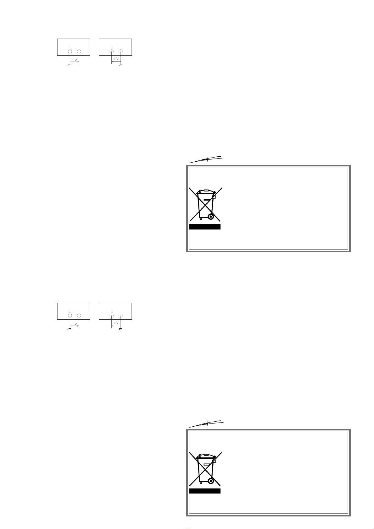
6.4 APPLICATIONS
Les sorties étant flottantes, dans les limites de la tension de mode commun, la
référence est donnée par le montage Fig. 2.
L’alimentation peut délivrer une tension positive ou négative.
7 MAINTENANCE
Aucun entretien particulier n’est à envisager pour cet appareil.
Eviter la poussière, l’humidité, les chocs, votre appareil vous en sera reconnaissant.
Pour le nettoyage, utiliser un chiffon doux à poussière.
Si les témoins ne s’allument pas à la mise sous tension, vérifier:
Si l’interrupteur Marche-Arrêt est enfoncé
La présence de la tension secteur
Le raccordement au réseau
Le fusible de protection
8 SERVICE APRES-VENTE
Le Service après-vente est assuré par la Société
elc
.
La période de garantie est de un an pièces et main-d’oeuvre. Ne sont toutefois pas
garantis les pannes ou défauts provenant d’une mauvaise utilisation de l’appareil
(tension secteur non conforme, chocs ...) ou ayant été dépanné hors de nos services
ou des ateliers de nos agences autorisées.
FRANCAIS
9. DECLARATION DE CONFORMITE
suivant l’ISO /IEC guide 22 et l’EN45014
Fabricant : elc
Adresse : 59 avenue des Romains 74000 Annecy France
déclare que le produit
Nom : Alimentations stabilisée
Numéro : AL936N
est conforme aux spécifications suivantes :
Sécurité : EN 61010-1 : 2001
EN 61558-2-4 : 1999 sur le transformateur
CEM : EN 61326-1 : 2006
Informations complémentaires :
Le produit ci-dessus est conforme aux exigences de la Directive Basse Tension
73/23/CEE, de la Directive Compatibilité Electromagnétique 89/336/CEE
et de la directive 93/68/CEE.
Annecy, le 29 octobre 2008
Henri Curri, gérant
Fig. 2
FRANCAIS
6.4 APPLICATIONS
Les sorties étant flottantes, dans les limites de la tension de mode commun, la
référence est donnée par le montage Fig. 2.
L’alimentation peut délivrer une tension positive ou négative.
7 MAINTENANCE
Aucun entretien particulier n’est à envisager pour cet appareil.
Eviter la poussière, l’humidité, les chocs, votre appareil vous en sera reconnaissant.
Pour le nettoyage, utiliser un chiffon doux à poussière.
Si les témoins ne s’allument pas à la mise sous tension, vérifier:
Si l’interrupteur Marche-Arrêt est enfoncé
La présence de la tension secteur
Le raccordement au réseau
Le fusible de protection
8 SERVICE APRES-VENTE
Le Service après-vente est assuré par la Société
elc
.
La période de garantie est de un an pièces et main-d’oeuvre. Ne sont toutefois pas
garantis les pannes ou défauts provenant d’une mauvaise utilisation de l’appareil
(tension secteur non conforme, chocs ...) ou ayant été dépanné hors de nos services
ou des ateliers de nos agences autorisées.
Fig. 2
9. DECLARATION DE CONFORMITE
suivant l’ISO /IEC guide 22 et l’EN45014
Fabricant : elc
Adresse : 59 avenue des Romains 74000 Annecy France
déclare que le produit
Nom : Alimentations stabilisée
Numéro : AL936N
est conforme aux spécifications suivantes :
Sécurité : EN 61010-1 : 2001
EN 61558-2-4 : 1999 sur le transformateur
CEM : EN 61326-1 : 2006
Informations complémentaires :
Le produit ci-dessus est conforme aux exigences de la Directive Basse Tension
73/23/CEE, de la Directive Compatibilité Electromagnétique 89/336/CEE
et de la directive 93/68/CEE.
Annecy, le 29 octobre 2008
Henri Curri, gérant
ÉLIMINATION DES DÉCHETS PAR LES UTILISATEURS DANS LES
MÉNAGESPRIVÉSAUSEINDEL’UNIONEUROPÉENNE
Ce symbole sur le produit ou sur son emballage indique que ce
produit ne doit pas être jeté avec vos autres ordures ménagères.
Ilestdevotreresponsabilité de vous débarrasser devosdéchets
en les apportant à un point de collecte désigné pour le recyclage
des appareils électriques et électroniques.
La collecte et le recyclage séparés de vos déchets au moment
del’éliminationcontribueraà conserver lesressourcesnaturelles
et à garantir un recyclage respectueux de l’environnement et de
la santé humaine. Pour plus d’informations sur le centre de
recyclage le plus proche de votre domicile, contactez la mairie
la plus proche, le service d’élimination des ordures ménagères
ou le magasin où vous avez acheté le produit.

- 11 -
- 11 -
4000 4 200_Rev1 - 12/094000 4 200_Rev1 - 12/09
ENGLISH
TABLE OF CONTENTS
1 PRELIMINARY INFORMATION Page 11
2 DESCRIPTION Page 11
2.1 INTRODUCTION Page 11
2.2 FUNCTIONS OF THE INSTRUMENT Page 11
2.3 ACCESSORIES OF THE INSTRUMENT Page 12
2.4 SYMBOLS AND DEFINITIONS Page 12
2.5TECHNICAL SPECIFICATIONS Page 12
3 WORKING PRINCIPLE Page 13
3.1 REMINDER ABOUT THE RECTANGULAR
CHARACTERISTIC Page 13
3.2 CONSPECTUS OF THE DIFFERENT MODES Page 13
4 PRELIMINARY INSTRUCTIONS Page 14
4.1 PACKAGING Page 14
4.2 MOUNTING AND PLACING OF THE INSTRUMENT Page 15
5 BEFORE USE Page 15
6 INSTRUCTIONS FOR USE Page 15
6.1 SAFETY INSTRUCTIONS Page 15
6.2 CONTROLS Page 15
6.3 BEFORE MEASURING Page 17
6.4 APPLICATIONS Page 17
7 MAINTENANCE Page 18
8 AFTER SALES SERVICE Page 18
9 DECLARATION OF CONFORMITY Page 18
1. PRELIMINARY INFORMATION
Manufacturer : elc 59, avenue des Romains 74000 ANNECY - FRANCE
Phone : +33 (0)4 50 57 30 46 Fax : +33 (0)4 50 57 45 19
Instrument : STABILIZED POWER SUPPLY
Trademark : elc
Type : AL 936N
2. DESCRIPTION
2.1 INTRODUCTION
Youjustboughta POWER SUPPLYtypeelcAL936N. We thankyouandcongratulate
you for your good choice.
The elc company proposes a wide range of POWER SUPPLIES and many other
electronic test instruments : LF AND FUNCTION GENERATORS, FREQUENCYMETER, PANEL
METERS...
This instrument has been conceived according to the European standard EN
61010-1 and supplied in good condition. This electrical instrument is intend to
professionals, industrials and educatives using.This instructions manual contains
information and notes, which must be respected by the purchaser, in order to ensure
a safe working and to maintain the instrument in good condition.
2.2 FUNCTIONS OF THE INSTRUMENT
Thispracticalinstrument,to be used in laboratory,willgiveyou satisfaction in all uses.
Three independant power supplies regulated in voltage and current constitute this
instrument :
Two power supplies (A and B or Master and Slave) deliver each 0 to 30V and 0 to
3A in output. They can be coupled according to 4 modes :
Separated : 2 x 0 to 30V and 0 to 3A
Tracking : ± 0 to 30V and 0 to 3A
Series : 0 to 60V and 0 to 3A
Parallel : 0 to 30V and 0 to 6A
Moreover,anactingonthestandbymode connects the output terminals of the power
supplies. The standby mode is automatic, as soon as a mode is selected.
The output voltages and currents are displayed by 3 digit-voltmeters and ammeters.
Jointly used with the current setting and in standby mode only, the Icc short-circuit
selection allows to set the maximum current of the 2 power supplies.
An auxiliary power supply, with two display modes :
2V to 5.5V - 3A : The voltage is variable, the current is 3A
5.5V to 15V - 1A : The voltage is variable, the current is 1A
The output voltage or current of the power-supply is displayed by a 3 digit-indicator.
- 12 -
- 12 -
4000 4 200_Rev1 - 12/09
4000 4 200_Rev1 - 12/09
ENGLISH
2.3 ACCESSORIES OF THE INSTRUMENT
Your power-supply AL 936N is delivered with its mains cord and «EUROPE» bipolar
plug + Earth and its instructions manual.
2.4 SYMBOLS AND DEFINITIONS
You will find following symbols on the instruments :
2.5 TECHNICAL SPECIFICATIONS AT 230V AND 23°C
CAUTION ! RISK OF
ELECTRIC SHOCK
EARTH TERMINAL CAUTION ! TO REFER
TO THE MANUAL
2.3 ACCESSORIES OFTHE INSTRUMENT
Your power-supply AL 936N is delivered with its mains cord and «EUROPE» bipolar
plug + Earth and its instructions manual.
2.4 SYMBOLS AND DEFINITIONS
You will find following symbols on the instruments :
2.5 TECHNICAL SPECIFICATIONS AT 230V AND 23°C
CAUTION ! RISK OF
ELECTRIC SHOCK
EARTH TERMINAL CAUTION ! TO REFER
TO THE MANUAL
SELECTION OF THE FUNCTIONAL MODES
SPECIFICATIONS MASTER AND SLAVE POWER SUPPLIES AUXILIARY POWER SUPPLY
Separated Tracking Series Parallel Variable Fixed
O u t p u t v o l t a g e 0 to 30V ± 0 to 30V 0 to 60V 0 to 30V 2V to 5.5V 5.5V to 15V
Minimum value 0 to ± 10mV 0 to ± 10mV 0 to ± 20mV 0 to ± 10mV < 2V -
Ripple 1mV 1mV 1mV 1mV 1mV 1mV
Regulation / load from 0 to 100% 12mV 12mV 50mV 24mV 12mV 10mV
Regulation / mains from -6 to +7% 5mV 5mV 5mV 5mV 5mV 1mV
Internal resistance 4mΩ4mΩ16mΩ4mΩ4mΩ4mΩ
Response time / load from 10 to 90% 30µs 30µs 30µs 30µs 100µs 60µs
Display resolution 100mV 100mV 100mV 100mV 10mV 100mV
Display Digital voltmeter with 3 digits of 14mm
O u t p u t c u r r e n t 0 to 3A ± 0 to 3A 0 to 3A 0 to 6A 3A 1A
Minimum value 10mA 10mA 10mA 20mA - -
Ripple 1mA 1mA 1mA 4mA - -
Regulation / load from 0 to 100% 2mA 2mA 4mA 8mA - -
Regulation / mains from -6 to +7% 1mA 1mA 1mA 5mA - -
Display resolution 10mA 10mA 10mA 10mA 10mA 10mA
Display Digital ammeter with 3 digits of 14mm
!
!
- 13 -
- 13 -
4000 4 200_Rev1 - 12/094000 4 200_Rev1 - 12/09
ENGLISH
OTHER SPECIFICATIONS
Mains : 230V ± 10%, 50 / 60Hz
Mains input : «EUROPE» CEE 22 receptacle with bipolar cord + Earth
Powering : Bipolar switch
Outputs : Safety terminals, VDE 0110 standard
Consumption : 430VA
Electric strength : 2300VAC between input and output
2300VAC between input and frame
100VDC between output and frame
Dimensions : L=285mm H=151mm D=225mm
Casing : Polycarbonate front face silk-screen printed
Epoxy paint on case
Weight : 6.8kg
Condition of use : +5°C to +40°C
Condition of storage : -10°C to +50°C
Condition of humidity : see diagramm.
PROTECTIONS
Safety class : I
Against short-circuit, by current limiting.
Against excessive temperature rises :
- by temperature controlled ventilation
- by thermal circuit-breaker, built in the transformer
- by relay switching the secondary windings of the transformer
Against any overcurrent in the transformer :
-bytime-delayfuse3.15A 5x20 on the primary winding(accessibleonthebackside).
- by fast fuse F5A 5x20 on the secondary winding (inside the instrument).
STANDARDS
EMC : EN 55011 group 1 - class B
EN 50082-1 performance criterion A
SAFETY : EN 61010-1, overvoltage category II and pollution degree 2.
EN 61558-2-4, class II for the transformer.
3. WORKING PRINCIPLE
3.1 REMINDER ABOUT THE RECTANGULAR
CHARACTERISTIC
A power supply able to work at constant voltage or
current is called with rectangular characteristic
(Fig. 1).
The change from «constant voltage» working to
«constant current» working is automatic according
RL=Vs/Is
RL>Vs/Is
V
Vs
V1 RL>Vs/Is
I1 Is I
Fig.1
to the adjustments of Vs and Is and to the load applied at the output.
If the RL load resistance is higher than the ratio Vs/Is, the power supply works at
constant voltage for the value of the selected output voltage and with a
current limiting to Is.
If RL varies from the infinite to Vs/Is, I can vary from 0 to Is (I1 example) and the output
voltage is constant.
For the power-supply being able to work at constant voltage, the output current must
be lower than the selected limit current.
In the contrary case, the power supply changes over to the «constant current»
working.
If the RL load resistance is lower than the ratio Vs/Is, the power supply works at
constant current, for a current value selected and with a voltage limiting to Vs.
If RL varies from 0 to Vs/Is, V can vary from 0 to Vs and Is = constant (V1 example).
For the power supply being able to work at constant current, the output voltage has
to be set at the maximum of the specified values ; and the limit current has to be set
by an appropriate adjustment on acting on the Icc function.
Caution!whentheoutputlimit voltage and currentareset,so that the load resistance
is equal to the ratio Vs/Is, a working instability can occur.
3.2 CONSPECTUS OF THE DIFFERENT MODES
3.2.1 Separated Mode
The 2 power-supplies are independant and deliver each a voltage adjustable from
0 to 30V and a current adjustable from 0 to 3A.
3.2.2TrackingMode
Thismodeallows todeliver2 symmetricalvoltagesin relationtothemiddle pointformed
by the negative terminal of the Master power-supply "A" and the positive terminal of
OTHER SPECIFICATIONS
Mains : 230V ± 10%, 50 / 60Hz
Mains input : «EUROPE» CEE 22 receptacle with bipolar cord + Earth
Powering : Bipolar switch
Outputs : Safety terminals, VDE 0110 standard
Consumption : 430VA
Electric strength : 2300VAC between input and output
2300VAC between input and frame
100VDC between output and frame
Dimensions : L=285mmH=151mmD=225mm
Casing : Polycarbonate front face silk-screen printed
Epoxy paint on case
Weight : 6.8kg
Condition of use : +5°C to +40°C
Condition of storage : -10°C to +50°C
Condition of humidity : see diagramm.
PROTECTIONS
Safety class : I
Against short-circuit, by current limiting.
Against excessive temperature rises :
- by temperature controlled ventilation
- by thermal circuit-breaker, built in the transformer
- by relay switching the secondary windings of the transformer
Against any overcurrent in the transformer :
-bytime-delayfuse3.15A 5x20 on the primary winding(accessibleonthebackside).
- by fast fuse F5A 5x20 on the secondary winding (inside the instrument).
STANDARDS
EMC : EN 55011 group 1 - class B
EN 50082-1 performance criterion A
SAFETY : EN 61010-1, overvoltage category II and pollution degree 2.
EN 61558-2-4, class II for the transformer.
3. WORKING PRINCIPLE
3.1 REMINDER ABOUT THE RECTANGULAR
CHARACTERISTIC
A power supply able to work at constant voltage or
current is called with rectangular characteristic
(Fig. 1).
The change from «constant voltage» working to
«constant current» working is automatic according
RL=Vs/Is
RL>Vs/Is
V
Vs
V1 RL>Vs/Is
I1 Is I
Fig.1
to the adjustments of Vs and Is and to the load applied at the output.
If the RL load resistance is higher than the ratio Vs/Is, the power supply works at
constant voltage for the value of the selected output voltage and with a
current limiting to Is.
If RL varies from the infinite to Vs/Is, I can vary from 0 to Is (I1 example) and the output
voltage is constant.
For the power-supply being able to work at constant voltage, the output current must
be lower than the selected limit current.
In the contrary case, the power supply changes over to the «constant current»
working.
If the RL load resistance is lower than the ratio Vs/Is, the power supply works at
constant current, for a current value selected and with a voltage limiting to Vs.
If RL varies from 0 to Vs/Is, V can vary from 0 to Vs and Is = constant (V1 example).
For the power supply being able to work at constant current, the output voltage has
to be set at the maximum of the specified values ; and the limit current has to be set
by an appropriate adjustment on acting on the Icc function.
Caution!whentheoutputlimit voltage and currentareset,so that the load resistance
is equal to the ratio Vs/Is, a working instability can occur.
3.2 CONSPECTUS OFTHE DIFFERENT MODES
3.2.1SeparatedMode
The 2 power-supplies are independant and deliver each a voltage adjustable from
0 to 30V and a current adjustable from 0 to 3A.
3.2.2TrackingMode
Thismodeallows todeliver2 symmetricalvoltagesin relationtothemiddle pointformed
by the negative terminal of the Master power-supply "A" and the positive
8 0
5 0
3 1 4 0 ° C
%
m a x i m u m r e l a t i v e
m o i s t u r e
8 0
5 0
3 1 4 0 ° C
%
m a x i m u m r e l a t i v e
m o i s t u r e
Voltage display Current display Voltage display Current display
MASTER Power SLAVE Power
SEPARATED Mode
Current regulation Current regulation
STANDBY Mode
Voltage regulation Voltage regulation
MASTER Output SLAVE Output
Voltage display Current display Voltage display Current display
MASTER Power SLAVE Power
SEPARATED Mode
Current regulation Current regulation
STANDBY Mode
Voltage regulation Voltage regulation
MASTER Output SLAVE Output

- 14 -
- 14 -
4000 4 200_Rev1 - 12/09
4000 4 200_Rev1 - 12/09
ENGLISH
3.2.4 Parallel Mode
It allows to adjust the power-supply from 0 to 30V with a current from 0 to 6A. The
voltage and current regulations of the Slave power-supply "B" are driven from the
Master one "A" ; the magnitudes beeing displayed on the master power-supply.
theSlavepower-supply"B". The regulationoftheslavevoltage is drivenbythemaster
one. The current setting remains independant and adjustable from
0 to 3A for each power-supply.
3.2.5ModesoftheAuxiliarypower-supply
Two functional modes are possible :
«2V to 5.5V - 3A» mode : the auxiliary power-supply is adjustable from less than 2V
to 5.5V and delivers a current of 3A.
«5.5V to 15V - 1A» mode : the power-supply delivers a voltage from 5.5V to 15V with
a current of 1A.
The voltage is displayed with a 10mV resolution in the "2V to 5.5V" mode and with
a 100mV resolution in the "5.5V to 15V" mode.
3.2.3 Series Mode
It allows to adjust the power-supply from 0 to 60V with a current from 0 to 3A. The
voltage and current regulations of the Slave power-supply "B" are driven from the
Master one "A" ; the magnitudes being displayed on the Master power-supply.
Voltage display Current display
MASTER Power SLAVE Power
SERIES Mode
Current regulation
STANDBY Mode
Voltage regulation
MASTER Output SLAVE Output
Voltage display Current display Voltage display Current display
MASTER Power SLAVE Power
TRACKING Mode
Current regulation Current regulation
STANDBY Mode
Voltage regulation
MASTER Output SLAVE Output
Voltage display Current display
MASTER Power SLAVE Power
PARALLEL Mode
Current regulation
STANDBY Mode
Voltage regulation
MASTER Output (+)
AUXILIARY MODE
Variable 2 - 5.5V Voltage display
Voltage regulation 3A
Current display
Current regulation Variable 5.5 - 15V
1A
Power
Output
- 15 -
- 15 -
4000 4 200_Rev1 - 12/094000 4 200_Rev1 - 12/09
ENGLISH
4. PRELIMINARY INSTRUCTIONS
4.1 PACKAGING
During its transport, the power-supply is protected by a «Bull-pack» wrapping and
placed in a cardboard box avoiding any damage.
Keep this material, you may use it later on.
Packing list :
1 instructions manual 1 «Bull-pack» wrapping 1 cardboard wrapping
1 Power-supply : AL 936N 1 cardboard packing piece 1 Mains cord
4.2 MOUNTING AND PLACING OFTHE INSTRUMENT
For a natural and correct cooling, the power supply must stand on its four rubber
thrusts and all ventilation openings must be widely cleared.
To connect the mains cord in the «EUROPE» CEE22 receptacle at the rear of the
instrument.
5. BEFORE USE
To connect the p. supply to mains (230V) and to switch on with the «On/Off» switch.
6. INSTRUCTIONS FOR USE
6.1 SAFETY INSTRUCTIONS
Anyinterventioninsidethecasing,and particulary the fuses replacement,must
imperatively be effectued by a skilled staff.
The instrument must be used according to the instructions of this manual.
The plug of the mains cord being used as the switch off device, the instrument
mustbeconnected to asocketeasilyaccessible, which hasanearthconnection.
When this instrument has to be powered using a separated autotransformer in
order to get a voltage reduction, make sure that the common terminal is
connected to the pole earthed of the feeding circuit.
The common mode voltage between Earth and output terminals shall not
exceed 50V rms. In this case, a voltage judged dangerous (>60Vdc) can be
reached between one of the terminals and Earth.
In series or tracking mode, a voltage of 60V (judged dangerous) can be
available between the positive terminal of the Master power supply and the
negative one of the Slave power supply.
In these cases, it is necessary to use safety cords for the connection to the
instrument’soutputs.Moreover,the instruments connectedmustn’tgiveaccess
to conductive parts.
6.1.1 Description of the instrument’s rear panel
AMAINSRECEPTACLE
BTIME-DELAY FUSE 3.15A
The time-delay fuse (5x20mm 3.15A) can be replaced by a fuse
of same type and features.
6.2 CONTROLS
6.2.1 Controls description of the front panel
1 CURRENTDISPLAY
2 CURRENT REGULATION CONTROL
3 CURRENT ADJUSTMENT
4 VOLTAGE DISPLAY
5 VOLTAGE REGULATION CONTROL
6 VOLTAGE ADJUSTMENT
7 SELECTION OF THE SEPARATED MODE
8 SELECTION OF THE TRACKING MODE
9 SELECTION OF THE SERIES MODE
10 SELECTION OF THE PARALLEL MODE
11 SELECTION OF THE STANDBY MODE
12 VOLTAGE FINE ADJUSTMENT
13 POSITIVE TERMINAL
14 NEGATIVE TERMINAL
15 SELECTION OF THE SHORT-CIRCUIT
16 VOLTAGE FINE ADJUSTMENT
17 POSITIVE TERMINAL
18 NEGATIVE TERMINAL
19 «ON / OFF» SWITCH
20 POSITIVE TERMINAL
21 NEGATIVE TERMINAL
22 «VOLTMETER» MODE
23 SELECTION OF THE «VOLTMETER/AMMETER» MODE
24 «AMMETER» MODE
25 VOLTAGE ADJUSTMENT
26 VOLTAGE OR CURRENT DISPLAY (CF 23)
27 CURRENT ADJUSTMENT
28 CURRENT REGULATION CONTROL
29 CURRENT DISPLAY
30 SELECTION OF THE SHORT-CIRCUIT
31 VOLTAGE FAST ADJUSTMENT
32 VOLTAGEDISPLAY
33 VOLTAGE REGULATION CONTROL
34 FUNCTIONALEARTHTERMINAL
A
B
!
4. PRELIMINARY INSTRUCTIONS
4.1 PACKAGING
During its transport, the power-supply is protected by a «Bull-pack» wrapping and
placed in a cardboard box avoiding any damage.
Keep this material, you may use it later on.
Packing list :
1 instructions manual 1 «Bull-pack» wrapping 1 cardboard wrapping
1 Power-supply : AL 936N 1 cardboard packing piece 1 Mains cord
4.2 MOUNTING AND PLACING OF THE INSTRUMENT
For a natural and correct cooling, the power supply must stand on its four rubber
thrusts and all ventilation openings must be widely cleared.
To connect the mains cord in the «EUROPE» CEE22 receptacle at the rear of the
instrument.
5. BEFORE USE
To connect the p. supply to mains (230V) and to switch on with the «On/Off» switch.
6. INSTRUCTIONS FOR USE
6.1 SAFETY INSTRUCTIONS
Anyinterventioninsidethecasing,and particulary the fuses replacement,must
imperatively be effectued by a skilled staff.
The instrument must be used according to the instructions of this manual.
The plug of the mains cord being used as the switch off device, the instrument
mustbeconnected to asocketeasilyaccessible, which hasanearthconnection.
When this instrument has to be powered using a separated autotransformer in
order to get a voltage reduction, make sure that the common terminal is
connected to the pole earthed of the feeding circuit.
The common mode voltage between Earth and output terminals shall not
exceed 50V rms. In this case, a voltage judged dangerous (>60Vdc) can be
reached between one of the terminals and Earth.
In series or tracking mode, a voltage of 60V (judged dangerous) can be
available between the positive terminal of the Master power supply and the
negative one of the Slave power supply.
In these cases, it is necessary to use safety cords for the connection to the
instrument’soutputs.Moreover,the instruments connectedmustn’tgiveaccess
to conductive parts.
6.1.1 Description of the instrument’s rear panel
AMAINS RECEPTACLE
BTIME-DELAY FUSE 3.15A
The time-delay fuse (5x20mm 3.15A) can be replaced by a fuse
of same type and features.
6.2 CONTROLS
6.2.1 Controls description of the front panel
1 CURRENT DISPLAY
2 CURRENT REGULATION CONTROL
3 CURRENT ADJUSTMENT
4 VOLTAGE DISPLAY
5 VOLTAGE REGULATION CONTROL
6 VOLTAGE ADJUSTMENT
7 SELECTION OF THE SEPARATED MODE
8 SELECTION OF THE TRACKING MODE
9 SELECTION OF THE SERIES MODE
10 SELECTION OF THE PARALLEL MODE
11 SELECTION OF THE STANDBY MODE
12 VOLTAGE FINE ADJUSTMENT
13 POSITIVE TERMINAL
14 NEGATIVE TERMINAL
15 SELECTION OF THE SHORT-CIRCUIT
16 VOLTAGE FINE ADJUSTMENT
17 POSITIVE TERMINAL
18 NEGATIVE TERMINAL
19 «ON / OFF» SWITCH
20 POSITIVE TERMINAL
21 NEGATIVE TERMINAL
22 «VOLTMETER» MODE
23 SELECTION OF THE «VOLTMETER/AMMETER» MODE
24 «AMMETER» MODE
25 VOLTAGE ADJUSTMENT
26 VOLTAGE OR CURRENT DISPLAY (CF 23)
27 CURRENT ADJUSTMENT
28 CURRENT REGULATION CONTROL
29 CURRENT DISPLAY
30 SELECTION OF THE SHORT-CIRCUIT
31 VOLTAGE FAST ADJUSTMENT
32 VOLTAGE DISPLAY
33 VOLTAGE REGULATION CONTROL
34 FUNCTIONAL EARTH TERMINAL
A
B
!
!
!
!
!
!
!
!
!
!
!

- 16 -
- 16 -
4000 4 200_Rev1 - 12/09
4000 4 200_Rev1 - 12/09
ENGLISH
6.2.2Descriptionoftheoperatingcontrols
(19)
ON-OFFSWITCH
The graduation O indicates the position of the stop device.
(11)
SELECTIONOFTHE STANDBYMODE
In standby mode with lighting red Led, no voltage is available at the output
terminals of the Master and Slave power-supplies. An acting on the standby
mode connects the output terminals and a new acting disconnects them.
Moreover, the standby mode is automatic, as soon as a mode is selected.
(34)
FUNCTIONAL EARTH TERMINAL
Directly earthed from the frame. Allows to take the earth as reference for your
mounting. This connection in not aimed to ensure the continuity of the
protective conductor.
SEPARATED MODE of the A and B power-supplies
(
7)
SELECTION OF THE SEPARATED MODE
Allows the independant working of the A and B power-supplies.
(
6) (31)
VOLTAGE ADJUSTMENT
Allows the adjustment of a voltage between 0 and 30V.
(12) (16)
VOLTAGE FINE ADJUSTMENT
Makes the voltage adjusted by
(6) (31)
vary of about 2V.
(5) (33)
VOLTAGE REGULATION CONTROL
The lighting green Led shows that the power-supply works in voltage
regulation.
(4) (32)
VOLTAGE DISPLAY
Allows to read the voltage from 0 to 30V with a 100mV resolution.
(3) (27)
CURRENT ADJUSTMENT
Allows to adjust a current between 0 and 3A.
(15) (30)
SELECTION OF THE SHORT-CIRCUIT
In standby mode only and used jointly with
(3)
(27)
, allows the adjustment
of the output maximum current.
(2) (28)
CURRENT REGULATION CONTROL
Thelightingred Led showsthatthe power-supply worksincurrent regulation.
(1) (29)
CURRENT DISPLAY
Allows to read the current from 0 to 3A with a 10mA resolution.
(13) (17)
POSITIVE TERMINAL
(14) (18)
NEGATIVE TERMINAL
Components of the A power-supply
: (1) (2) (3) (4) (5) (6) (12) (13) (14) (15)
Components of the B power-supply
: (16) (17) (18) (27) (28) (29) (30) (31) (32) (33)
TRACKING MODE of the Master and Slave power-supplies
(8)
SELECTION OF THE TRACKING MODE
The tracking mode allows to get, between the
(13)
(14)
and
(17)
(
18)
terminals, two identical, but opposed, voltages from 0 to 30V.
(14)
(17)
POSITIVE and NEGATIVE TERMINALS
These terminals, connected internally, are the middle point of the tracking
power-supply.
(13)
POSITIVE TERMINAL
(18)
NEGATIVE TERMINAL
(6)
VOLTAGE ADJUSTMENT
Allows to adjust symmetrically a voltage between 0 and 30V.
(12)
VOLTAGE FINE ADJUSTMENT
Makes the voltage adjusted by
(6)
vary symmetrically from 0 to 2V.
(5) (33)
VOLTAGE REGULATION CONTROL
The lighting green Led shows that the power-supply works in voltage
regulation.
(4) (32)
VOLTAGE DISPLAY
Allows to read the voltage from 0 to 30V with a 100mV resolution.
(3) (27)
CURRENT ADJUSTMENT
Allows to adjust a current between 0 and 3A.
(15) (30)
SELECTION OF THE SHORT-CIRCUIT
In standby mode only and used jointly with
(3)
(27)
, allows the adjusment
of the output maximum current.
(2)
(28)
CURRENT REGULATION CONTROL
Thelightingred Led showsthatthe power-supply worksincurrent regulation.
(1)
(29)
CURRENT DISPLAY
Allows to read the current from 0 to 3A with a 10mA resolution.
CAUTION
(16)
(31)
are inactive.
SERIES MODE of the Master and Slave power-supplies
(9)
SELECTION OF THE SERIES MODE
The series mode of the 2 power-supplies allows to get a voltage from 0 to
60V at the
(13)
and
(18)
terminals, with a current from 0 to 3A.
(13)
POSITIVE TERMINAL
(18)
NEGATIVE TERMINAL
(6)
VOLTAGE ADJUSTMENT
Allows to adjust a voltage between 0 and 60V.
(12)
VOLTAGE FINE ADJUSTMENT
Makes the voltage adjusted by
(6)
vary of about 4V.
(5)
VOLTAGE REGULATION CONTROL
The lighting green Led shows that the power-supply works in voltage
regulation.
(4)
VOLTAGE DISPLAY
Allows to read the voltage from 0 to 60V with a 100mV resolution.
(3)
CURRENT ADJUSTMENT
Allows to adjust a current between 0 and 3A.
(15)
SELECTION OF THE SHORT-CIRCUIT
Jointly used with
(3)
and in standby mode only, allows the adjusment of the
output maximum current.
(2)
CURRENT REGULATION CONTROL
Thelightingred Led showsthatthe power-supply worksincurrent regulation.
(1)
CURRENT DISPLAY
Allows to read the current from 0 to 3A with a 10mA resolution.
6.2.2 Description of the operating controls
(19)
ON-OFF SWITCH
The graduation O indicates the position of the stop device.
(11)
SELECTION OF THE STANDBY MODE
In standby mode with lighting red Led, no voltage is available at the output
terminals of the Master and Slave power-supplies. An acting on the standby
mode connects the output terminals and a new acting disconnects them.
Moreover, the standby mode is automatic, as soon as a mode is selected.
(34)
FUNCTIONAL EARTH TERMINAL
Directly earthed from the frame. Allows to take the earth as reference for your
mounting. This connection in not aimed to ensure the continuity of the
protective conductor.
SEPARATED MODE of the A and B power-supplies
(
7)
SELECTION OF THE SEPARATED MODE
Allows the independant working of the A and B power-supplies.
(
6) (31)
VOLTAGE ADJUSTMENT
Allows the adjustment of a voltage between 0 and 30V.
(12) (16)
VOLTAGE FINE ADJUSTMENT
Makes the voltage adjusted by
(6) (31)
vary of about 2V.
(5) (33)
VOLTAGE REGULATION CONTROL
The lighting green Led shows that the power-supply works in voltage
regulation.
(4) (32)
VOLTAGE DISPLAY
Allows to read the voltage from 0 to 30V with a 100mV resolution.
(3) (27)
CURRENT ADJUSTMENT
Allows to adjust a current between 0 and 3A.
(15) (30)
SELECTION OF THE SHORT-CIRCUIT
In standby mode only and used jointly with
(3)
(27)
, allows the adjustment
of the output maximum current.
(2) (28)
CURRENT REGULATION CONTROL
Thelightingred Led showsthatthe power-supply worksincurrent regulation.
(1) (29)
CURRENT DISPLAY
Allows to read the current from 0 to 3A with a 10mA resolution.
(13) (17)
POSITIVE TERMINAL
(14) (18)
NEGATIVE TERMINAL
Components of the A power-supply
: (1) (2) (3) (4) (5) (6) (12) (13) (14) (15)
Components of the B power-supply
: (16) (17) (18) (27) (28) (29) (30) (31) (32) (33)
TRACKING MODE of the Master and Slave power-supplies
(8)
SELECTION OF THE TRACKING MODE
The tracking mode allows to get, between the
(13)
(14)
and
(17)
(
18)
terminals, two identical, but opposed, voltages from 0 to 30V.
(14)
(17)
POSITIVE and NEGATIVE TERMINALS
These terminals, connected internally, are the middle point of the tracking
power-supply.
(13)
POSITIVE TERMINAL
(18)
NEGATIVE TERMINAL
(6)
VOLTAGE ADJUSTMENT
Allows to adjust symmetrically a voltage between 0 and 30V.
(12)
VOLTAGE FINE ADJUSTMENT
Makes the voltage adjusted by
(6)
vary symmetrically from 0 to 2V.
(5) (33)
VOLTAGE REGULATION CONTROL
The lighting green Led shows that the power-supply works in voltage
regulation.
(4) (32)
VOLTAGE DISPLAY
Allows to read the voltage from 0 to 30V with a 100mV resolution.
(3) (27)
CURRENT ADJUSTMENT
Allows to adjust a current between 0 and 3A.
(15) (30)
SELECTION OF THE SHORT-CIRCUIT
In standby mode only and used jointly with
(3)
(27)
, allows the adjusment
of the output maximum current.
(2)
(28)
CURRENT REGULATION CONTROL
Thelightingred Led showsthatthe power-supply worksincurrent regulation.
(1)
(29)
CURRENT DISPLAY
Allows to read the current from 0 to 3A with a 10mA resolution.
CAUTION
(16)
(31)
are inactive.
SERIES MODE of the Master and Slave power-supplies
(9)
SELECTION OF THE SERIES MODE
The series mode of the 2 power-supplies allows to get a voltage from 0 to
60V at the
(13)
and
(18)
terminals, with a current from 0 to 3A.
(13)
POSITIVE TERMINAL
(18)
NEGATIVE TERMINAL
(6)
VOLTAGE ADJUSTMENT
Allows to adjust a voltage between 0 and 60V.
(12)
VOLTAGE FINE ADJUSTMENT
Makes the voltage adjusted by
(6)
vary of about 4V.
(5)
VOLTAGE REGULATION CONTROL
The lighting green Led shows that the power-supply works in voltage
regulation.
(4)
VOLTAGE DISPLAY
Allows to read the voltage from 0 to 60V with a 100mV resolution.
(3)
CURRENT ADJUSTMENT
Allows to adjust a current between 0 and 3A.
(15)
SELECTION OF THE SHORT-CIRCUIT
Jointly used with
(3)
and in standby mode only, allows the adjusment of the
output maximum current.
(2)
CURRENT REGULATION CONTROL
Thelightingred Led showsthatthe power-supply worksincurrent regulation.
(1)
CURRENT DISPLAY
Allows to read the current from 0 to 3A with a 10mA resolution.
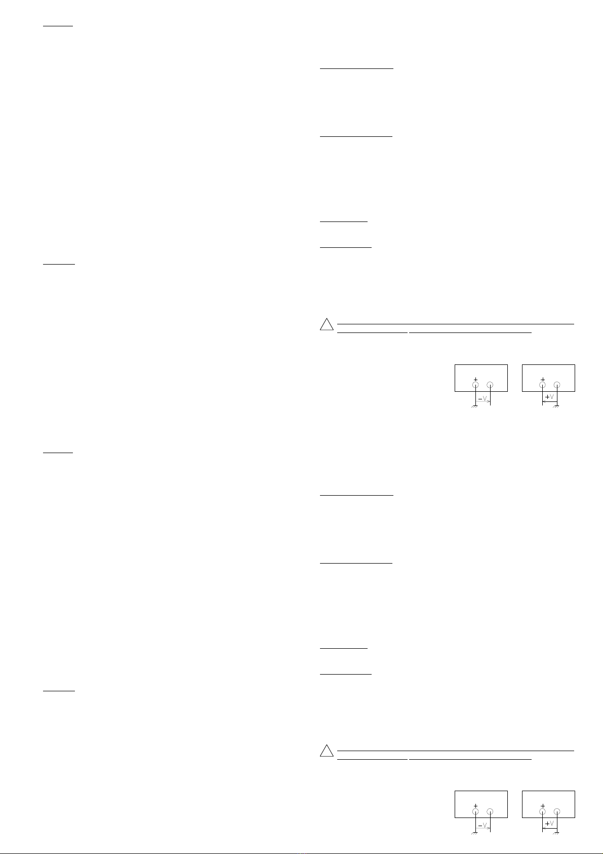
- 17 -
- 17 -
4000 4 200_Rev1 - 12/094000 4 200_Rev1 - 12/09
ENGLISH
CAUTION (14) (16) (17) (27) (28) (29) (30) (31) (32) (33) are inactive.
PARALLEL MODE of the Master and Slave power-supplies
(10) SELECTION OF THE PARALLEL MODE
The parallel mode of the 2 power-supplies allows to adjust, between the
(13) and (14) terminals, an output voltage from 0 to 30V, with a current
variable from 0 to 6A.
(13) POSITIVE TERMINAL
(14) NEGATIVE TERMINAL
(6) VOLTAGE ADJUSTMENT
Allows to adjust a voltage between 0 and 30V.
(12) VOLTAGE FINE ADJUSTMENT
Makes the voltage adjusted by (6) vary from 0 to 2V.
(5) VOLTAGE REGULATION CONTROL
The lighting green Led shows that the power-supply works in voltage
regulation.
(4) VOLTAGE DISPLAY
Allows to read the voltage from 0 to 30V with a 100mV resolution.
(3) CURRENT ADJUSTMENT
Allows to adjust a current between 0 and 6A.
(15) SELECTION OF THE SHORT-CIRCUIT
In standby mode only and used jointly with (3), allows the adjustment of
the output maximum current.
(2) CURRENT REGULATION CONTROL
The lighting red Led shows that the power-supply works in current
regulation.
(1) CURRENT DISPLAY
Allows to read the current from 0 to 6A with a 10mA resolution.
CAUTION (16) (17) (18) (27) (28) (29) (30) (31) (32) (33) are inactive.
AUXILIARY POWER SUPPLY
(23) SELECTION OF THE «VOLTMETER OR AMMETER» MODE
Allows to choose the display mode of the power-supply.
(22) CONTROL OF THE «AMMETER» MODE
The lighting red Led shows that the display is in «AMMETER» mode.
(24) CONTROL OF THE «VOLTMETER» MODE
The lighting red Led shows that the display is in «VOLTMETER» mode.
(25) VOLTAGE ADJUSTMENT
Allows to adjust a voltage between less than 2V and 15V.
(26) VOLTAGE OR CURRENT DISPLAY
Allows to read the output voltage or current according to the mode
selected.
The resolution is : 10mV in «VOLTMETER» mode fr. 2V to 5.5V - 3A
: 100mV in «VOLTMETER» mode fr. 5.5V to 15V - 1A
: 10mAin«AMMETER»mode.
(20) POSITIVETERMINAL
(21) NEGATIVE TERMINAL
6.3 BEFORE MEASURING
6.3.1 A and B power supplies or Master and Slave
Use at constant voltage
To choose the mode needed : Separated, Tracking, etc...
To set the current at the maximum value.
To set the voltage at the value needed.
To connect the load to the terminals corresponding to the mode.
To activate the standby mode, in order to connect the load.
To check the voltage regulation : lighting green Led.
Use at constant current
To choose the mode needed : Separated, Tracking, etc ...
To set the voltage at the maximum value.
To choose the working current, with the short-circuit and the setting.
To connect the load to the terminals corresponding to the mode.
To activate the standby mode, in order to connect the load.
To check the current regulation : lighting red Led.
6.3.2 Auxiliary power supply
To choose the mode needed : voltage or current display
2V to 5.5V - 3A : The voltage is present at the terminals.
The power-supply can deliver a current of 3A.
To set the voltage at the value needed. To connect the load.
5.5V to 15V - 1A : The voltage is present at the terminals.
The power-supply can deliver a current of 1A.
To set the voltage at the value needed. To connect the load.
6.3.3 Cautions
Before applying the load, to always set the power supply.
To connect the load using insulated leads with sufficient diameter.
To disconnect the load before switching off the power-supply.
To keep the instrument away from dust.
Any interruption of the protective conductor outside the casing may render the
instrument dangerous. The intentional interruption is forbidden.
6.4 APPLICATIONS
As outputs are floating, within the limits of the common mode voltage, the reference
is given by the mounting diagram (Fig. 2).
The power-supply can deliver a positive
or negative voltage.
Fig. 2
CAUTION (14) (16) (17) (27) (28) (29) (30) (31) (32) (33) are inactive.
PARALLEL MODE of the Master and Slave power-supplies
(10) SELECTION OF THE PARALLEL MODE
The parallel mode of the 2 power-supplies allows to adjust, between the
(13) and (14) terminals, an output voltage from 0 to 30V, with a current
variable from 0 to 6A.
(13) POSITIVE TERMINAL
(14) NEGATIVE TERMINAL
(6) VOLTAGE ADJUSTMENT
Allows to adjust a voltage between 0 and 30V.
(12) VOLTAGE FINE ADJUSTMENT
Makes the voltage adjusted by (6) vary from 0 to 2V.
(5) VOLTAGE REGULATION CONTROL
The lighting green Led shows that the power-supply works in voltage
regulation.
(4) VOLTAGE DISPLAY
Allows to read the voltage from 0 to 30V with a 100mV resolution.
(3) CURRENT ADJUSTMENT
Allows to adjust a current between 0 and 6A.
(15) SELECTION OF THE SHORT-CIRCUIT
In standby mode only and used jointly with (3), allows the adjustment of
the output maximum current.
(2) CURRENT REGULATION CONTROL
The lighting red Led shows that the power-supply works in current
regulation.
(1) CURRENT DISPLAY
Allows to read the current from 0 to 6A with a 10mA resolution.
CAUTION (16) (17) (18) (27) (28) (29) (30) (31) (32) (33) are inactive.
AUXILIARY POWER SUPPLY
(23) SELECTION OF THE «VOLTMETER OR AMMETER» MODE
Allows to choose the display mode of the power-supply.
(22) CONTROL OF THE «AMMETER» MODE
The lighting red Led shows that the display is in «AMMETER» mode.
(24) CONTROL OF THE «VOLTMETER» MODE
The lighting red Led shows that the display is in «VOLTMETER» mode.
(25) VOLTAGE ADJUSTMENT
Allows to adjust a voltage between less than 2V and 15V.
(26) VOLTAGE OR CURRENT DISPLAY
Allows to read the output voltage or current according to the mode
selected.
The resolution is : 10mV in «VOLTMETER» mode fr. 2V to 5.5V - 3A
: 100mV in «VOLTMETER» mode fr. 5.5V to 15V - 1A
: 10mA in «AMMETER» mode.
(20) POSITIVE TERMINAL
(21) NEGATIVE TERMINAL
6.3 BEFORE MEASURING
6.3.1 A and B power supplies or Master and Slave
Use at constant voltage
To choose the mode needed : Separated, Tracking, etc...
To set the current at the maximum value.
To set the voltage at the value needed.
To connect the load to the terminals corresponding to the mode.
To activate the standby mode, in order to connect the load.
To check the voltage regulation : lighting green Led.
Use at constant current
To choose the mode needed : Separated, Tracking, etc ...
To set the voltage at the maximum value.
To choose the working current, with the short-circuit and the setting.
To connect the load to the terminals corresponding to the mode.
To activate the standby mode, in order to connect the load.
To check the current regulation : lighting red Led.
6.3.2 Auxiliary power supply
To choose the mode needed : voltage or current display
2V to 5.5V - 3A : The voltage is present at the terminals.
The power-supply can deliver a current of 3A.
To set the voltage at the value needed. To connect the load.
5.5V to 15V - 1A : The voltage is present at the terminals.
The power-supply can deliver a current of 1A.
To set the voltage at the value needed. To connect the load.
6.3.3 Cautions
Before applying the load, to always set the power supply.
To connect the load using insulated leads with sufficient diameter.
To disconnect the load before switching off the power-supply.
To keep the instrument away from dust.
Any interruption of the protective conductor outside the casing may render the
instrument dangerous. The intentional interruption is forbidden.
6.4 APPLICATIONS
As outputs are floating, within the limits of the common mode voltage, the reference
is given by the mounting diagram (Fig. 2).
The power-supply can deliver a positive
or negative voltage.
Fig. 2
!
!
- 18 -
- 18 -
4000 4 200_Rev1 - 12/09
4000 4 200_Rev1 - 12/09
ENGLISH
7. MAINTENANCE
No particular maintenance is required for this instrument.
To avoid dust, humidity, shocks ; your instrument will appreciate it.
For the cleaning, please use a smooth duster.
If indicators do not light up on switching on, to check :
That the ON/OFF switch is pressed
The mains voltage
The connection to mains
The protective fuse.
8. AFTER SALES SERVICE
The after sales Service is ensured by the
elc
company.
Duringoneyear,spareparts and workmanship are guaranteed.Thisguaranteedoes
not apply to instruments presenting defects or faults caused by an improper use
(wrong mains voltage, shocks ...) or which have been repaired outside our factory or
the repair shops of our authorized agencies.
9.DECLARATIONOFCONFORMITY
according to ISO / IEC guide 22 and EN45014
Manufacturer :
elc
Address : 59, av. des Romains - 74000 Annecy - France
declares the product
Name : Stabilized power-supply
Number : AL936N
conformable to following specifications :
Safety : EN 61010-1 : 2001
EN 61558-2-4 : 1999 for the transformer
CEM : EN 61326-1 : 2006
Further information :
Theproductaboveisconformable to the requirementsofthe«LowVoltage» directive
2006/95/CE and of the «Electromagnetic Compatibility» directive 2004/108/CE.
Annecy, october 29, 2008
Henri Curri, manager
7. MAINTENANCE
No particular maintenance is required for this instrument.
To avoid dust, humidity, shocks ; your instrument will appreciate it.
For the cleaning, please use a smooth duster.
If indicators do not light up on switching on, to check :
That the ON/OFF switch is pressed
The mains voltage
The connection to mains
The protective fuse.
8. AFTER SALES SERVICE
The after sales Service is ensured by the
elc
company.
Duringoneyear,spareparts and workmanship are guaranteed.Thisguaranteedoes
not apply to instruments presenting defects or faults caused by an improper use
(wrong mains voltage, shocks ...) or which have been repaired outside our factory or
the repair shops of our authorized agencies.
9.DECLARATIONOFCONFORMITY
according to ISO / IEC guide 22 and EN45014
Manufacturer :
elc
Address : 59, av. des Romains - 74000 Annecy - France
declares the product
Name : Stabilized power-supply
Number : AL936N
conformable to following specifications :
Safety : EN 61010-1 : 2001
EN 61558-2-4 : 1999 for the transformer
CEM : EN 61326-1 : 2006
Further information :
Theproductaboveisconformable to the requirementsofthe«LowVoltage» directive
2006/95/CE and of the «Electromagnetic Compatibility» directive 2004/108/CE.
Annecy, october 29, 2008
HenriCurri,manager
ELIMINATION OF MANUFACTURING WASTES BY THE PRIVATE
USERSINTHEEU
This symbol written in the product or in its packaging indicates
thatthisproductmust not be throwinthegarbage with your other
waste.
Its your responsability to rid of your manufacturing wastes
bringing it to a specialized sorting office for the recycling of
electrical and electronic instruments.
Collectionandrecyclingseparated of yourwasteswillcontribute
to preserve natural resources and guarantee a recycling
respectful of the Environment and human health.
Forfurtherinformationconcerningthe recycling center near your placeofresidence,
contact your town hall, the elimination service of garbage heap or the store where
you bought the instrument.

- 19 -
- 19 -
4000 4 200_Rev1 - 12/094000 4 200_Rev1 - 12/09
DEUTSCH
INHALTSVERZEICHNIS
1 VORINFORMATIONEN Seite 19
2 BESCHREIBUNG Seite 19
2.1 EINFÜHRUNG Seite 19
2.2 FUNKTIONSBESCHREIBUNG DES GERÄTES Seite 19
2.3 ZUSATZTEILE DES GERÄTES Seite 20
2.4 SYMBOL UND DEFINITION Seite 20
2.5 TECHNISCHE DATEN Seite 20
3 BETRIEBSPRINZIP Seite 21
3.1 DIE RECHTECKIGE KENNLINIE Seite 21
3.2 ÜBERSICHT ÜBER DIE VERSCHIED. BETRIEBSARTEN Seite 21
4 VORBEMERKUNGEN Seite 22
4.1 VERPACKUNG Seite 22
4.2 MONTAGE UND INBETRIEBNAHME DES GERÄTES Seite 23
5 VORBEREITUNG ZUM BETRIEB Seite 23
6 BEDIENUNGSANWEISUNGEN Seite 23
6.1 SICHERHEITSANWEISUNGEN Seite 23
6.2 BEDIENUNGSELEMENTE Seite 23
6.3 VORBEREITUNGEN FÜR DIE MESSUNGEN Seite 25
6.4 ANWENDUNGEN Seite 25
7 WARTUNG Seite 26
8 KUNDENDIENST Seite 26
9 ÜBEREINSTIMMUNGSERKLÄRUNG Seite 26
1. VORINFORMATIONEN
Hersteller : elc 59 avenue des Romains 74000 ANNECY - FRANKREICH
Telefon : 33 (0)4 50 57 30 46 Telefax : 33 (0)4 50 57 45 19
Gerät : STABILISIERTES NETZGERÄT
Marke : elc
Typ : AL 936N
2. BESCHREIBUNG
2.1 EINFÜHRUNG
Siehabengeradedasstabilisierte Netzgerät, Typ elc AL936Nerworben.Wir danken
Ihnen dafür und gratulieren Ihnen für Ihre gute Wahl.
elc bietet eine groβe Palette von NETZGERÄTEN an, aber auch zahlreiche andere
elektronische Geräte : NIEDERFREQUENZ-GENERATOREN, FREQUENZMESSER, ANZEIGE-
INSTRUMENTE...
Dieses Gerät wurde gemäβder europäischen Norm EN 61010-1 gebaut und in
gutem Zustand geliefert. Dieses elektrisches gerät ist für einen einsatz im beruf, in
der industrie und für schulungszwecke gedacht. Das vorliegende Handbuch enthält
Informationen und Anweisungen, die vom Käufer eingehalten werden müssen, um
einen reibungslosen Betrieb zu sichern und das Gerät in gutem Zustand zu halten.
2.2 FUNKTIONSBESCHREIBUNG
Dieses praktische Gerät für den Laborbetrieb wird Ihnen mit seinen zahlreichen
Möglichkeiten volle Zufriedenheit geben.
Dieses Gerät besteht aus drei unabhängigen Strom- und Spannungsgeregelten
Netzgeräten.
Zwei Netzgeräte (A und B oder «Master» und «Slave») erzeugen im Ausgang 0 bis
30V und 0 bis 3A.
Sie können nach 4 Funktionsarten geschaltet werden :
Getrennt(separated) : 2 x 0 bis 30V und 0 bis 3A
Symmetrisch (tracking): ± 0 bis 30V und 0 bis 3A
Reihe (series) : 0 bis 60V und 0 bis 3A
Parallel (parallel) : 0 bis 30V und 0 bis 6A.
Darüber hinaus schaltet das Betätigen des Standby-Modus (Warte-Modus) die
Ausgangsklemmen der Netzgeräte an. Der Standby-Modus ist selbständig aktiv,
sobald ein Modus ausgewählt ist.
Ausgangsspannungund-strom werdenvon3-stelligenVoltmeternundAmperemetern
angezeigt. Das Betätigen der Kurzschluβtaste, Icc, ermöglicht die Einstellung des
maximalen Stroms der beiden Netzgeräte.
Es darf nur zusammen mit der Stromeinstellung im Standby-Modus benutzt werden.
Ein Hilfsnetzgerät mit zwei Anzeigearten :
2V bis 5.5V - 3A : Die Spannung ist variabel, der Strom beträgt 3A
5.5V bis 15V - 1A : Die Spannung ist variabel, der Strom beträgt 1A.
DieAusgangsspannungoder-stromdesNetzgeräteswirdvoneinem3-stelligenAnzeigegerät
angezeigt.
DEUTSCH
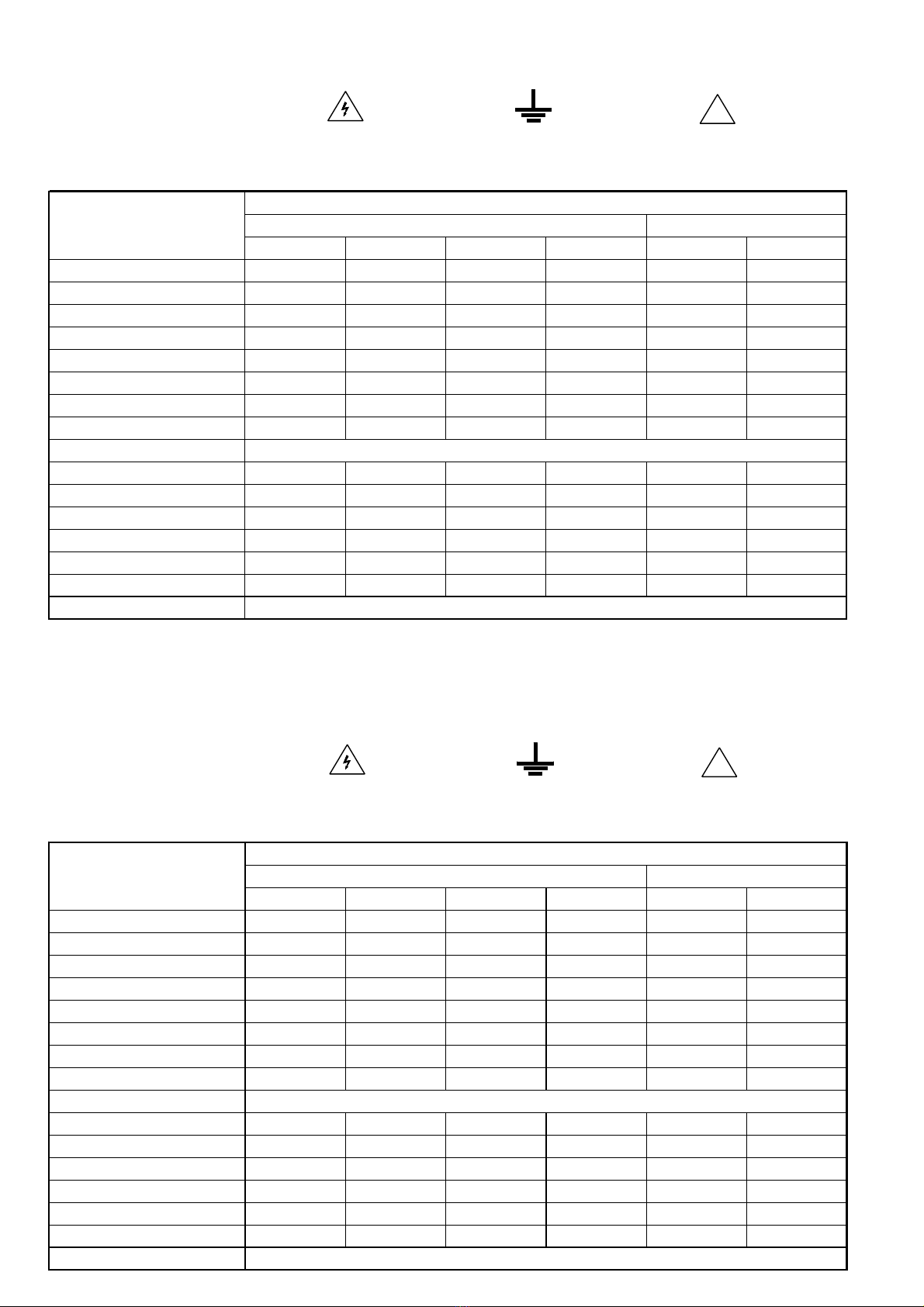
- 20 -
- 20 -
4000 4 200_Rev1 - 12/09
4000 4 200_Rev1 - 12/09
DEUTSCH
2.3 ZUSATZTEILE DES GERÄTES
Ihr Netzgerät AL 936N wird Ihnen mit seinem zweipoligen, geerdeten «Europa»
Anschluβkabel und seinem Bedienungshandbuch geliefert.
2.4 SYMBOL UND DEFINITION
2.5 TECHNISCHE DATEN BEI 230V UND 23°C
VORSICHT,
ELEKTRISCHE
GEFAHR !
FUNKTIONNELLE
ERDKLEMME
VORSICHT,
BEDIENUNGSANLEITUNG
LESEN !
DEUTSCH
!
!
MÖGLICHE BETRIEBSARTEN
TECHNISCHE DATEN "MASTER" UND "SLAVE" NETZGERÄTE HILFSNETZGERÄT
Getrennt Symmetrisch Reihe Parallel Variabel Fest
A u s g a n g s s p a n n u n g 0 bis 30V ± 0 bis 30V 0 bis 60V 0 bis 30V 2V bis 5.5V 5.5V bis 15V
Minimalwert 0 bis ± 10mV 0 bis ± 10mV 0 bis ± 20mV 0 bis ± 10mV < 2V -
Restwelligkeit 1mV 1mV 1mV 1mV 1mV 1mV
Regelung / Ladung von 0 bis 100% 12mV 12mV 50mV 24mV 12mV 10mV
Regelung / Netz von -6 bis +7% 5mV 5mV 5mV 5mV 5mV 1mV
Innenwiderstand 4mΩ4mΩ16mΩ4mΩ4mΩ4mΩ
Antwortzeit für Ladung von 10 bis 90% 30µs 30µs 30µs 30µs 100µs 60µs
Anzeigeauflösung 100mV 100mV 100mV 100mV 10mV 100mV
Anzeige 3-stelliges Digitalvoltmeter (14 mm hoch)
A u s g a n g s s t r o m 0 bis 3A ± 0 bis 3A 0 bis 3A 0 bis 6A 3A 1A
Minimalwert 10mA 10mA 10mA 20mA - -
Restwelligkeit 1mA 1mA 1mA 4mA 1mA 1mA
Regelung / Ladung von 0 bis 100% 2mA 2mA 4mA 8mA - -
Regelung / Netz von -6 bis +7% 1mA 1mA 1mA 5mA - -
Anzeigeauflösung 10mA 10mA 10mA 10mA 10mA 10mA
Anzeige 3-stelliges Digitalamperemeter (14mm hoch)
Table of contents
Languages:
Other ELC Power Supply manuals


Popular Power Supply manuals by other brands

TDK-Lambda
TDK-Lambda HWS 1500 Series instruction manual

Longwei Electric
Longwei Electric LW1510KD quick start guide

Emerson
Emerson NetSure 5100 user manual

Wavetronix
Wavetronix Click 210 Installation & quick start guide

Schlage
Schlage PS906 installation instructions

Gold Note
Gold Note PSU-7 owner's manual


