ELC ALR3002M User manual
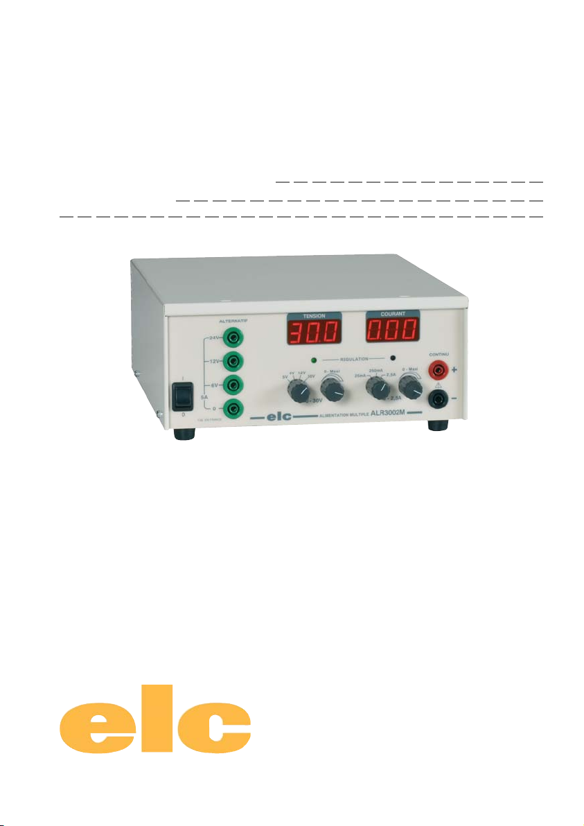
ALIMENTATION MULTIPLE
MULTIPLE POWER SUPPLY
UNIVERSAL-STROMVERSORGUNGSGERÄT
MANUEL D'INSTRUCTIONS
INSTRUCTIONS MANUAL
BEDIENUNGSHANDBUCH
Courant Continu/DC Current/Gleichstrom :
0 - 5, 6, 12 ou/or/oder 30V
0 - 25 mA, 250 mA ou/or/oder 2,5 A
Courant Alternatif/AC Current/Wechselstrom :
6 V,12 V et/and/und 24 V - 5 A
ALR3002M
Construction électronique

- 2 -
40004332-01/22
FRANCAIS
I
O
12V
ALTERNATIF
0
6V
5A
FAB . EN FRA NC E ALR3002M
ALIMENTATION MULTIPLE
elc
5V 12V 30V
0 - Maxi
6V
0 - 2,5A0 - 30V
25mA
250mA
2,5A
0 - Maxi
REGULATION CONTINU
!
24V
TENSION COURANT
5
4
2
1
86
7
9
FACE ARRIÈRE
BACKPANEL
10
3
11
FACE AVANT
FRONTPANEL

- 3 -
4000 4 332- 01/22
FRANCAIS
TABLE DES MATIERES
1 - RENSEIGNEMENTS PRELIMINAIRES .......................................................... Page 3
1-1 PRÉSENTATION ...................................................................................................... Page 3
1-2 PRESCRIPTIONS DE SÉCURITÉ ........................................................................... Page 3
1-3 SYMBOLES ET DÉFINITIONS ................................................................................ Page 3
2 - INSTRUCTIONS PRELIMINAIRES ............................................................... Page 4
2-1 DÉBALLAGE ET REMBALLAGE .......................................................................... Page 4
2-2 CARACTÉRISTIQUES TECHNIQUES ................................................................... Page 4
3 - VUE D’ENSEMBLE ....................................................................................... Page 4
3-1 ORGANES DE COMMMANDES ............................................................................. Page 4
3-2 DESCRIPTION DE LA FACE ARRIERE ................................................................. Page 5
4 - PRINCIPE DE FONCTIONNEMENT .............................................................. Page 5
4-1 LIMITE DE FONCTIONNEMENT ............................................................................ Page 5
4-2 RAPPEL SUR LA CARACTÉRISTIQUE RECTANGULAIRE ............................... Page 5
5 - FONCTIONNEMENT ....................................................................................... Page 5
5-1 MONTAGE ET MISE EN PLACE DE L’APPAREIL ................................................. Page 5
5-2 UTILISATION ........................................................................................................... Page 5
6 - MAINTENANCE .............................................................................................. Page 6
7 - SERVICE APRES VENTE .............................................................................. Page 6
8 - DECLARATION DE CONFORMITE ................................................................. Page 6
1 - RENSEIGNEMENTS PRELIMINAIRES
1-1 PRÉSENTATION
Vousvenezd’acquérir uneALIMENTATIONSTABILISEE avec régulationde courant detypeALR3002M. Nousvous
en remercions et vous félicitons de votre choix. elc c’est aussi de nombreux appareils électroniques : ALIMENTATIONS,
FRÉQUENCEMÈTRE, APPAREILS DE TABLEAU, BOITES ÀDECADES...
Cetappareil aété construitconformément àla normeeuropéenneEN 61010-1et aété fournienparfaitétat.Cetappareil
électrique est destiné aux usages professionnels, industriels et éducatifs. Le présent manuel d’instruction contient
destextes d’informationset d’avertissementsquidoivent êtrerespectés parl’acheteur pourassurer unfonctionnement
sûr et maintenir l’appareil en bon état.
Constructeur : elc 59, avenue des Romains 74000 ANNECY - FRANCE
Téléphone : +33 (0)4 50 57 30 46 Télécopie : +33 (0)4 50 57 45 19
Site Internet : www.elc.fr
Instrument : ALIMENTATIONSTABILISEE
Marque : ELC
Type : ALR3002M
Alimentation : 230V ± 10% alternatif 50/60 Hz
1-2 PRÉSCRIPTIONS DE SÉCURITÉ
L’appareildoitêtre utilisé conformément auxinstructions de ce document.
Conçu pour un usage intérieur, ne pas l'exposer à la pluie.
LESCIRCUITSALTERNATIF ETCONTINUPEUVENTETREUTILISESCONJOINTEMENT,
MAISAVEC UNEPUISSANCEMAXI DE120W.
la prise du cordon secteur étant utilisée comme dispositif de sectionnement, l’appareil doit être
raccordé sur un socle de prise secteur (230V 50/60Hz) aisément accessible.
Pourune bonne convection,l’alimentation doitreposer sur ses4 butéescaoutchouc et laface arrière doitêtre
largementdégagée.
Aucune intervention n’est autorisée à l’intérieur de l’appareil.
1-3 SYMBOLES ET DÉFINITION
Vous trouverez les symboles ci-après sur le matériel
ATTENTION ! ATTENTION!
RISQUE DE SEREFERER
CHOCELECTRIQUE AUMANUEL
!
!
- 4 -
40004332-01/22
FRANCAIS
2 - INSTRUCTIONS PRELIMINAIRES
2-1 DÉBALLAGE ET REMBALLAGE
L’emballage de l’alimentation ALR3002M est conçu pour la protéger lors de son transport.
Conservez-le, il pourra être utile ultèrieurement.
Liste de colisage
1 manuel d’instructions 1 housse plastique de protection 1 Alimentation : ALR3002M
2 flasques en carton
2-2 CARACTÉRISTIQUESTECHNIQUES A 230V ET 23°C
2-2-1 Tensionsalternatives
Tension de sortie : 6V,12Vet24V±3%(+15%maxiàvide)avec pointcommun
Sorties : douilles de sécurité diamètre 4mm
Intensité de sortie : 5 A
Protections : Contre les courts-circuits et les surintensités par
disjoncteursthermiquesincorporés (Réarmement
automatique après avoir supprimé le défaut)
2-2-2 Tensionscontinues
Tension de sortie : 4 gammes 5 V, 6 V, 12 V et 30 V réglable de 0 V à Vmax.
Sorties : douilles de sécurité diamètre 4 mm
Ondulationrésiduelle : 1 mV efficace
Régulation pour une variation de charge 0 à 100% : 10 mV
Régulation pour variation secteur de -6% à +7% : 5 mV
Résistance interne : 4mΩ
Visualisation : LED verte de régulation de tension
Voltmètre numérique 3 digits de 14mm
Résolution du voltmètre : 10 mV sur 5 V et 6 V, 100 mV sur 12 V et 30 V
Intensité de sortie : 3 gammes 25 mA, 250 mA et 2.5 A réglable de 0 A à Imax.
Régulation pour une variation de charge 0 à 100% : 2 mA
Régulation pour variation secteur de -6% à +7% : 1 mA
Visualisation : LED rouge de régulation d’intensité
Ampèremètre numérique 3 digits de 14mm
Résolutionde l’ampèremètre : 100 μA sur 25 mA, 1 mA sur 250 mA, 10 mA sur 2.5 A
AUTRES CARACTÉRISTIQUES
Alimentation : Secteur 230 V ± 10%, 50/60 Hz
Entrée secteur : Cordon 2 pôles
Consommation : 200 VA
Encombrement : P = 238 mm L = 218 mm H = 90 mm
Masse : 4,2 Kg
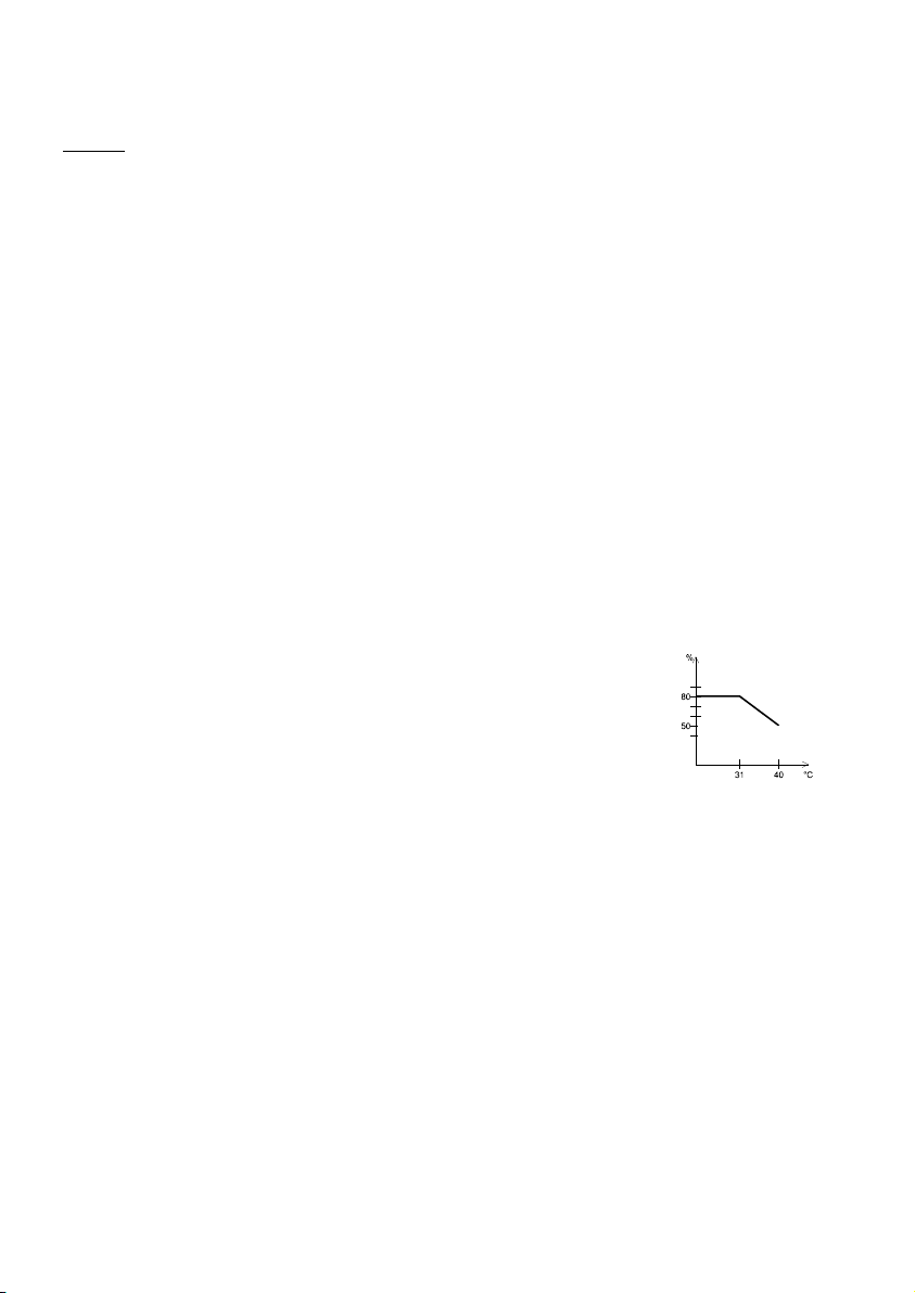
Conditions d’utilisation : +5°C à +40°C
Conditions de stockage : -10°C à +50°C
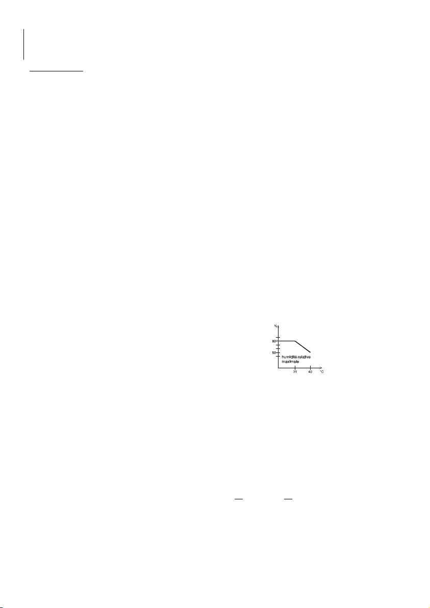
Conditionsd’humidité : (voir figure 1)
Sécurité : Classe II sécurité renforcée entre le secteur et les sorties.
Norme EN 61010-1 - Catégorie de surtension II degré de pollution 2
CEM : EN61326-1
Rigiditédiélectrique : 2300 V entre entrée et sortie et entre entrée et chassis.
PROTECTIONS :
Classe de sécurité : II
Contre les cours-circuits : par régulation de courant et disjoncteur thermique
Contre les échauffements excessifs : par ventilation controlée,
par disjonction des alimentations,
par relais sur le transformateur.
par disjoncteur thermique incorporé dans le transformateur
Contre les surintensités : par fusibles 5x20 interne (F1 : F5A 250V, F2 : T3.15A 250V)
3- VUE D’ENSEMBLE
(voir page 2)
3-1 ORGANES DE COMMANDE
1Interrupteur général
2Sorties alimentation alternatif
3Afficheur tension alimentation continu
4Afficheur intensité alimentation continu
Fig.1
- 5 -
4000 4 332- 01/22
FRANCAIS
5Sortie alimentation continu
6Réglage du courant
7Sélection de la gamme de courant
8Réglage de la tension
9Sélection de la gamme de tension
3-2DESCRIPTION DELAFACEARRIERE
10 Cordon secteur
11 Logement pour le cordon secteur
4 - PRINCIPE DE FONCTIONNEMENT
4-1 LIMITATIONDEFONCTIONNEMENT
Dansle casd’uneutilisationconjointedes sortiesalternatives etcontinus, lapuissancetotaledesortie nedevra
pas dépasser 120W. Des disjonctions en température peuvent s’activer si cette puissance est dépassée.
Trois cas possible :
- la sortie en courant alternatif est interrompu (disjoncteur interne en série sur les sorties)
- la sortie en courant continu tombe à 0 Volt et 0 ampère (contrôle de la température sur le dissipateur)
- l’alimentation s’éteint complètement (disjoncteur interne au transformateur)
Dans tous les cas, débrancher les utilisations et attendre le réarmement automatique, qui s’effectuera dès que la
température interne sera suffisamment basse.
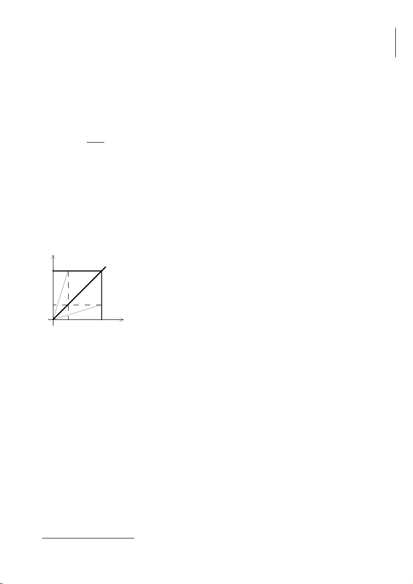
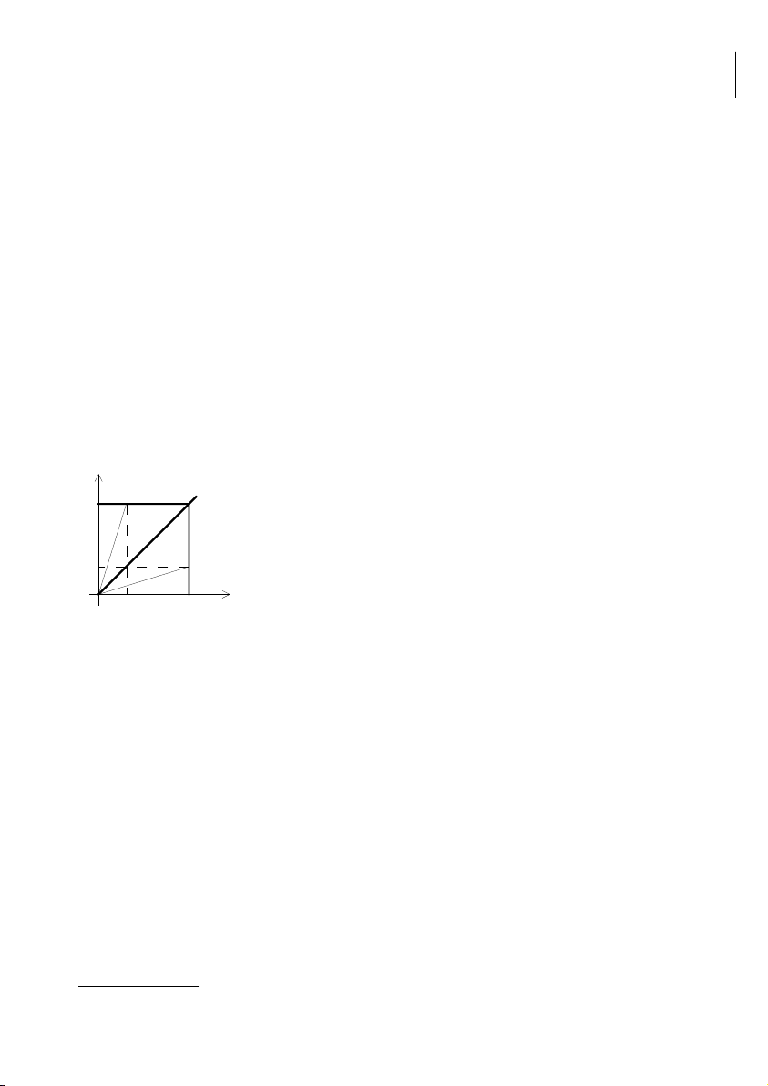
4-2 RAPPEL SUR LA CARACTERISTIQUE RECTANGULAIRE
Unealimentation pouvantfonctionner àtensionconstante ouà courantconstant estdite àcaractéristiquerectangulaire
(Fig. 2). Le passage du fonctionnement «tension constante» au fonctionnement «courant constant» est automatique
en fonction des réglages de Vs et de Is et de la charge appliquée à la sortie.
Si la résistance de charge RL est supérieure au rapport Vs/Is, l’alimentation fonctionne à tension constante pour
la valeur de la tension de sortie sélectionnée et avec une limitation de courant à Is.
Si RL varie de l’infini à Vs/Is, I peut varier de 0 à Is (exemple I1) et la tension de sortie
est constante.
Ainsi pour que l’alimentation fonctionne à tension constante, le courant de sortie doit
être inférieur au courant limite sélectionné.
Danslecas contraire,l’alimentationchangedefonctionnementetpasseàcourantconstant.
Si la résistance de charge RL est inférieur au rapport Vs/Is, l’alimentation fonctionne
à courant constant, pour une valeur de courant sélectionnée et avec une limitation
de tension à Vs. Si RL varie de 0 à Vs/Is, V peut varier de 0 à Vs et Is = constant
(exemple V1). Ainsi, pour que l’alimentation fonctionne à courant constant, il faut que
le réglage de la tension de sortie soit au maximum des valeurs spécifiées.
Attention, lorsque les réglages de tension et de courant limite de sortie sont tels que la résistance de charge est
égale au rapport Vs/Is, cela peut provoquer une instabilité de fonctionnement.
5 - FONCTIONNEMENT
5-1 MONTAGE ET MISE EN PLACE DE L’APPAREIL
Une poignée est montée sur l’alimentation pour en faciliter le transport.
Pour un fonctionnement optimal, l’alimentation doit reposer sur ses 4 butées caoutchouc, la face arrière doit être
largement dégagée pour ne pas bloquer le flux d’air du ventilateur.
Déplier le cordon secteur de son logement et le connecter dans un socle de prise 230 V~, votre appareil est prêt
à fonctionner.
5-2 UTILISATION
Appuyer sur Ide l'interrupteur Marche / Arrêt [1], les afficheurs s’éclairent, votre alimentation est en fonctionnement.
L’ALR3002M possède deux alimentations distinctes et complètement séparées.
5-2-1Alimentation Alternative
Les trois sorties alternatives [2] 6, 12, 24 V avec point commun 0 sont protégées par des disjoncteurs thermiques
(type PTC) qui s'ouvrent dès que le courant de sortie dépasse 5 A sur une des sorties. Le réarmement s'effectue
en automatique dès que le défaut est supprimé et que la température du disjoncteur est redevenue normale.
Il est possible d’utiliser plusieurs sorties dans la mesure où la somme des courants ne dépasse pas 5 ampères.
5-2-2 AlimentationContinue
Les valeurs de la tension et du courant disponible sur la sortie continue [5] sont réglées au moyen des boutons [6]
[7] [8] [9] et affichées sur [3] [4].
Utilisation à tension constante
Régler le courant au maxi ou à une valeur maximale souhaitée par [6] [7].
Sélectionner la gamme de tension souhaité par [9] : 5, 6, 12 ou 30 Volts.
RL=Vs/Is
RL>Vs/Is
V
Vs
V1
Fig.2
RL>Vs/Is
I1 Is I

- 6 -
40004332-01/22
FRANCAIS
Régler la tension à la valeur souhaitée par [8] sur l’afficheur [3].
Connecter la charge sur les douilles [5].
Contrôler la régulation de tension par la LED verte éclairée et le courant consommé par l’afficheur [4].
Utilisation à courant constant
Régler la tension au maxi ou à une valeur maximale souhaitée par [8] [9].
Sélectionner la gamme de courant souhaité par [7] : 25 mA, 250 mA ou 2.5 A.
Faire le court-circuit sur les douilles [5] et régler le courant à la valeur souhaitée par [6] sur l’afficheur [4].
Enlever le court-circuit et connecter la charge sur les douilles [5].
Contrôler la régulation de courant par la LED rouge éclairée et sa valeur sur l’afficheur [4].
5.2.3Précautions
Toujours régler l’alimentation avant d’appliquer la charge.
Connecter la charge avec des cordons isolés de diamètre suffisant (1 mm²).
Déconnecter la charge avant l’arrêt de l’alimentation.
Stocker l’appareil à l’abri de la poussière.
Un circuit de contrôle de la température commande le ventilateur, il ne fonctionne que lorsque cela est nécessaire.
6 - MAINTENANCE
Aucunentretien particulier n’està envisager pourcet appareil. Eviterla poussière, l’humidité,les chocs,votreappareil
vous en sera reconnaissant. Pour le nettoyage, utiliser un chiffon doux à poussière.
Si l’afficheur ne s'éclaire pas à la mise sous tension, vérifier :
- si l'interrupteur Marche - Arrêt est activé
- le raccordement au réseau
- la présence de la tension secteur
7 - SERVICE APRES-VENTE
Le service après-vente est assuré par la société elc.
Sauf accord particulier, la garantie contractuelle est de 24 mois, pièces et main d’oeuvre.
Nesont toutefoispas garantislespannesoudéfauts provenantd’une mauvaiseutilisation del’appareil (tensionsecteur
non conforme, chocs...) ou ayant été dépanné hors de nos services ou des ateliers agréés de nos agences.
8 - DECLARATION UE DE CONFORMITE
Fabricant : ELC
Adresse : 59, avenue des Romains 74000 Annecy France
déclare que le produit
Nom : ALIMENTATIONSTABLISEE
Type : ALR3002M
est conforme aux exigences des Directives :
Basse Tension 2014/35/UE, Compatibilité Electromagnétique 2014/30/UE etRoHs2011/65/UE.
Les normes harmonisées suivantes ont été appliquées :
Sécurité : EN61010-1:2010
CEM : EN61326-1:2013
Annecy le 04 janvier 2022 Henri Curri, gérant
ELC OFFRE À SES CLIENTS DES
SOLUTIONS DE RECYCLAGE
Afin de remplir ses obligations, elc adhère à Ecosystem et finance la filière
decollecte etderecyclageagrééepourlesdéchets électriquesprofessionnels
(DEEE Pro). Cet engagement volontaire de elc, permet à ses clients de
bénéficierde solutions simpleset gratuitespourassurer lerecyclage deleurs
alimentations électriques, module de secours, générateurs de fonctions et
sondes oscilloscopes.
Ainsi, les clients de notre société peuvent se défaire gratuitement de leurs matériels EEE professionnels
(désignés précédemment) usagés. Ils obtiennent, certificat à la clé, l'assurance d'un traitement rigoureux
conforme à la règlementation. Il leur suffit de faire appel à Ecosystem qui leur indiquera la solution de collecte
la plus adaptée à leur besoin. Pour connaître toutes les solutions de collecte : https://www.ecosystem.eco

- 7 -
4000 4 332-EN-GE - 01/22
TABLE OF CONTENTS
1 - PRELIMINARY INFORMATIONS .................................................................... Page 7
1-1 DESCRIPTION ......................................................................................................... Page 7
1-2 SAFETY INSTRUCTIONS .......................................................................................Page 7
1-3 SYMBOLS AND DEFINITIONS ............................................................................... Page 7
2 - PRELIMINARY INSTRUCTIONS ................................................................... Page 8
2-1 PACKING .................................................................................................................. Page 8
2-2 TECHNICAL FEATURES ........................................................................................ Page 8
3 - OVERALL VIEW ........................................................................................... Page 8
3-1 CONTROL DESCRIPTION ...................................................................................... Page 8
3-2 BACK PANEL DESCRIPTION ................................................................................ Page 9
4 -WORKING PRINCIPLES ............................................................................... Page 9
4-1WORKING LIMITS ................................................................................................... Page 9
4-2 REMINDER ON RECTANGULAR CHARACTERISTICS ..................................... Page 9
5 - OPERATION ................................................................................................... Page 9
5-1 MOUNTING AND PLACING OF THE INSTRUMENT ........................................... Page 9
5-2 USE ........................................................................................................................... Page 9
6 - MAINTENANCE .............................................................................................. Page 10
7 - AFTER SALES SERVICE .............................................................................. Page 10
8 - DECLARATION OF CONFORMITY ................................................................. Page 10
1 - PRELIMINARY INFORMATIONS
1-1 INTRODUCTION
You have just purchased a LINEAR AND REGULATED POWER SUPPLY type : ALR3002M. We thank you and
congratulate you for your good choice. elc also proposes many electronic test instruments : POWER SUPPLIES,
FREQUENCY METER, PANEL METERS, DECADES BOXES...
Thisdevice wasmanufactured inaccordancewithEuropeanstandardEN 61010-1 andwas suppliedin goodconditions.
This instrument is intended to professional, industrial and educational uses. This instructions manual contains
informations and warnings the buyer must comply with in order to ensure safe and sustained operation.
Manufacturer : elc 59, avenue des Romains 74000 ANNECY - FRANCE
Phone : +33 (0)4 50 57 30 46 Fax : +33 (0)4 50 57 45 19
Web site : www.elc.fr
Instrument : LINEARANDREGULATEDPOWERSUPPLY
Brand : ELC
Type : ALR3002M
Main input voltage: 230 V ± 10% alternatif 50/60 Hz
1-2 SAFETY INSTRUCTIONS
This instrument must be used according to the instructions of this manual.
Made to be used indoors, do not expose to the rain.
THEAC AND DCCIRCUITS CAN BEUSED JOINTLYBUTWITH AMAX POWER OF120 W.
Theplug ofthe feedingcablebeing usedasthe switchoffdevice,theinstrumentmustbeconnected
to a main socket (230 V 50/60 Hz) easily accessible.
For anatural andcorrect cooling,the generator muststandonitsfourrubberthrusts andthe back
must be widely cleared.
No intervention is authorized inside the casing.
1-3 SYMBOLS AND DEFINITION
You will find following symbols on the instrument :
CAUTION ! CAUTION!
RISKOF ELECTRIC SHOCK REFERTOMANUAL
!
!
ENGLISH
- 8 -
40004332-EN-GE -01/22
2 - PRELIMINARY INSTRUCTIONS
2-1 PACKAGING
The packing material of the power supply ALR3002M is intended to protect it during its transportation.
Keep it, it may be useful later one.
Packing list
1 instructions manual 1 plastic protecting bag 1 power supply : ALR3002M
2 cardboard packing piece
2-2 TECHNICAL FEATURES AT 230 V AND 23°C
2-2-1 AC voltages
Output voltage : 6V,12Vand 24V± 3%(+15%max withoutload) withcommonpoint
Outputs : 4 mm diameter safety sockets
Output current : 5 A
Protections : Against short-circuits and overcurrent by incorporated thermal
circuit breaker (automatic rearmament after having deleted the
defect)
2-2-2 DC voltages
Output voltage : 4 ranges 5 V, 6V, 12 V and 30 V adjustable from 0 V to V max.
Outputs : 4 mm diameter safety sockets
Ripple : 1 mV rms
Regulation for a load change from 0 to 100% : 10mV
Regulation for a line change from -6% to +7% : 5 mV
Internal resistance : 4mΩ
Visualization : Voltage regulation green LED
3 x 14 mm digits digital voltmeter
Voltmeter resolution : 10 mV on 5 V and 6 V, 100 mV on 12 V and 30 V
Output current : 3 ranges 25 mA, 250 mA and 2,5 A adjustable from 0 A to I max.
Regulation for a load change from 0 to 100% : 2 mA
Regulation for a line change from -6% to +7% : 1 mA
Visualization : Current regulation red LED
3 x 14 mm digits digital ammeter
Ammeterresolution : 100 μA on 25 mA, 1 mA on 250 mA, 10 mA on 2,5 A
OTHERS CHARACTERISTICS
Main input voltage : 230 V ± 10 %, 50/60 Hz
Input voltage : Cord with 2 poles
Consumption : 200 VA
Dimensions : L = 238 mm H = 218 mm D = 90 mm
Weight : 4,2 Kg
Conditions of use : +5°C to +40°C
Conditions of storage : -10°C to +50°C
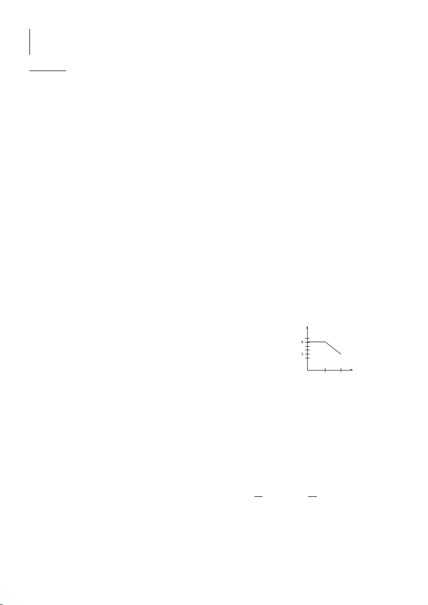
Conditions of moisture : (see G.1)
Safety : Class II reinforced safety between main input voltage and outputs.
EN 61010-1 standard - Overvoltage category II, pollution degree 2
EMC : EN61326-1
Electric strenght : 2300 V between input and output and between input and chassis.
PROTECTIONS :
Safety class : II
Against short circuits : by current regulation and thermal circuit breaker
Againstovertemperature : by controlled ventilation,
by power supplies shutdown,
by relay on the transformer,
by thermal circuit breaker incorporated on the transformer
Against overcurrent : by internal 5x20 fuses (F1 : F5A 250 V , F2 : T3.15A 250 V)
3- OVERALL VIEW
(see page 2)
3-1 CONTROLS DESCRIPTION
1Main switch
2AC outputs
3DC voltage display
4DC current display
G.1
8 0
5 0
3 1 4 0 ° C
%
m a x i m u m r e l a t i v e
m o i s t u r e
ENGLISH
- 9 -
4000 4 332-EN-GE - 01/22
5DC output
6Currentadjustment
7Current range selection
8Voltage adjustment
9Voltage range selection
3-2BACKPANEL DESCRIPTION
10 Main input voltage cord
11 Main input voltage cord housing
4 - WORKING PRINCIPLE
4-1 WORKINGLIMITS
In the case of jointly use of AC and DC outputs, the total output power should not exceed 120 W.
Temperatureshutdowncan appear ifthispower is overridden.
3 possible cases :
- AC current output is stopped (internal circuit breaker in serie on the outputs).
- DC current output falls to 0 Volt and 0 Amp (temperature control of the heat sinks)
- The power supply completely switched off (internal circuit breaker on the transformer)
In any cases, disconnect the uses and wait for the automatic rearmament that will start as soon as the internal
temperature will be low enough.
4-2 REMINDER ON RECTANGULAR CHARACTERISTICS
A power supply that can work with constant voltage or constant current is said rectangular characteristics (D. 2).
The transition from «constant voltage»operation towards «constant current»operation is automatic according to the
adjustments of Vs and Is and to the load applied to the output.
If load resistance RL is superior to the Vs/Is ratio, the power supply works in constant voltage for the output voltage
value chosen and with a current limit to Is.
IfRLvaries from infinite toVs/Is,I can vary from0 to Is (exampleI1)and output voltage
is constant.
Thus, to make the power supply works in constant voltage, the output current should
be inferior to the selected limit current.
In the contrary case, the power supply changes its way of operation and passes in
constant current. If load resistance RL is inferior to Vs/Is ratio, the power supply works
in constant current, for a selected current value and with a voltage limit to Vs. If RL varies
from 0 to Vs/Is, V can vary from 0 to Vs and Is = constant (example V1). Thus, to
make the power supply works in constant current, the output voltage adjustment must
be at the maximum of the specified values.
Caution : when the adjustments of the output limit voltage and current are such as the load resistance is equal to
the Vs/Is ratio, this can lead to an instability of operation.
5 - WORKING
5-1 MOUNTING AND PLACING OFTHE INSTRUMENT
There is an handle on the top of the power supply to make the transportation easier.
For an optimal operation, the power supply must stand on its 4 rubber thrusts. The back panel must be widely cleared
not to block the air flow of the fan.
Unfold the main power cord of its housing and connect it to a 230 V AC socket, your instrument is ready to work.
5-2 USE
Push on the «I» of the ON/OFF switch [1], the indicators light up, your power supply is working.
ALR3002M has 2 distinct and completely separated power supplies.
5-2-1ACoutputs
The three AC outputs [2] 6, 12, 24 V with common point 0 are protected by thermal circuit breaker (PTC type) that
works as soon as the output current exceed 5 A on one of the outputs. The rearmament is automatic as soon as
the defect is deleted and the circuit breaker temperature is back to normal.
It’s possible to use several outputs if the current sum does not exceed 5 A.
5-2-2 DCoutputs
Voltage and current values available on the DC output [5] are adjustable by the knobs [6] [7] [8] [9] and displayed
on [3] [4].
Constant voltage use
Adjust the current to max or to max desired value by [6] [7].
Select the desired voltage range by [9] : 5, 6, 12 or 30 Volts.
Adjust the voltage to the desired voltage by [8] on the display [3].
RL=Vs/Is
RL>Vs/Is
V
Vs
V1
D.2
RL>Vs/Is
I1 Is I
ENGLISH

- 10 -
40004332-EN-GE -01/22
Connect the load on the sockets [5].
Control the voltage regulation by the enlightened green LED and the current consumed by the display [4].
Constant current use
Adjust voltage to max or to a max desired value by [8] [9].
Select the desired current range by [7] : 25 mA, 250 mA or 2,5 A.
Do a short circuit on the sockets [5] and adjust the current to desired value by [6] on the display [4].
Take off the short-circuit and connect the load on sockets [5].
Control the current regulation by the enlightened red LED and its value on the display [4].
5.2.3Precautions
Always adjust the power supply before connecting the load.
Connect the load with sufficient diameter (1mm²) insulated cord.
Disconnect the load before switching off the ALR3002M.
Avoid dust for the storage of the instrument.
A temperature control circuit controls the fan, it works only when necessary.
6 - MAINTENANCE
No particular maintenance is required for this instrument. Avoid dust, humidity, shocks : your instrument will
be grateful to you for that. For cleaning, please use a smooth duster :
If indicator does not light up when plugging, check :
- if ON/OFF switch is activated
- the connection to the main input voltage
- Main voltage presence
7 - AFTER SALES SERVICE
During TWO YEARS, spare parts and workmanship are guaranteed. This guarantee does not apply to instrument
presentingdefects orfailurescausedbyan improperuse. Returnexpensesareborneby theclient. Onlydevicesreturned
witha datedpurchasinginvoicecanbe recoveredbytheguarantee.Any interventioncarried outbyunauthorizedpersons
or organizations, shall void the guarantee.
8 - EU DECLARATION OF CONFORMITY
Manufacturer : ELC
Address : 59, avenue des Romains 74000 Annecy FRANCE
declares the product
Name : REGULATEDPOWER SUPPLY
Type : ALR3002M
conformable to the requirements of the directives :
Low voltage 2014/35/UE, Electromagnetic Compatibility 2014/30/UE and RoHs 2011/65/UE.
The following harmonized standards have been applied :
Safety : EN61010-1:2010
EMC : EN61326-1:2013
Annecy, on January 04, 2022 H. CURRI Manager
ELIMINATION OF MANUFACTURING WASTES BY THE PRIVATE USERS IN THE EU
This symbol written in the product or in its packaging indicates that this product must not
be throw in the garbage with your other waste.
Its your responsability to rid of your manufacturing wastes bringing it to a specialized sorting
office for the recycling of electrical and electronic instruments.
Collection and recycling separated of your wastes will contribute to preserve natural
resources and guarantee a recycling respectful of the Environment and human health.
Forfurther information concerningthe recycling centernear yourplaceof residence,contact
your town hall, the elimination service of garbage heap or the store where you bought the
instrument.
ENGLISH

- 11 -
4000 4 332-EN-GE - 01/22
!
TABLE OF CONTENTS
1 - EINLEITENDE ANGABEN ............................................................................. Page 11
1-1 BESCHREIBUNG .................................................................................................... Page 11
1-2 SICHERHEITSVORSCHRIFTEN ............................................................................. Page 11
1-3 SYMBOLE UND DEFINITION ................................................................................. Page 11
2 - EINLEITENDE ANGABEN ............................................................................ Page 12
2-1 AUSPACKEN UND WIEDERVERPACKEN ............................................................ Page 12
2-2TECHNISCHE DATEN ............................................................................................. Page 12
3 - GESAMTANSICHT ........................................................................................ Page 12
3-1 BEFEHLSGEBER .................................................................................................... Page 12
3-2 BESCHREIBUNG DER GERÄTERÜCKSEITE ...................................................... Page 13
4 - FUNKTIONSPRINZIP .................................................................................... Page 13
4-1 FUNKTIONSBEGRENZUNG .................................................................................. Page 13
4-2 HINWEIS ZUR RECHTECKCHARAKTERISTIK ................................................... Page 13
5 - BETRIEB ........................................................................................................ Page 13
5-1 MONTAGE UND AUFSTELLUNG DES GERÄTS ................................................. Page 13
5-2 BEDIENUNG ............................................................................................................ Page 13
6 - WARTUNG .........................................................................................................................Page 14
7 - KUNDENDIENST ............................................................................................ Page 14
8 - KONFORMITÄTSERKLÄRUNG ....................................................................... Page 14
1 - EINLEITENDE ANGABEN
1-1 BESCHREIBUNG
Siehaben einSTABILISIERTES STROMVERSORGUNGSGERÄTmitStromregelungvomTypALR3002Merworben.
Wirdanken Ihnenfür IhrVertrauenund gratulierenIhnen zuIhrer Wahl.elcbietetauch zahlreicheweitere elektronische
Geräte an: STROMVERSORGUNGSGERÄTE, FREQUENZMESSER, SCHALTTAFELGERÄTE, DEKADEN-
WIDERSTANDSKÄSTEN,USW.
Das nach der Europäischen Norm EN 61010-1 ausgelegte Gerät wurde in einwandfreiem Zustand geliefert. Das
Elektrogerät ist für den gewerblichen, industriellen und schulischen Gebrauch bestimmt. Die Bedienungsanleitung
enthält Informationstexte und Warnhinweise, die vom Käufer zu beachten sind, um einen sicheren Betrieb zu
gewährleisten und das Gerät in ordnungsgemäßem Zustand zu erhalten.
Hersteller : elc 59 avenue des Romains 74000 ANNECY / FRANKREICH
Telefon : +33 (0)4 50 57 30 46 Fax : +33 (0)4 50 57 45 19
Website : www.elc.fr
Gerät: : STABILISIERTESSTROMVERSORGUNGSGERÄT
Marke : ELC
Gerätetyp : ALR3002M
Stromversorgung : 230V ± 10% Wechselstrom 50/60 Hz
1-2 SICHERHEITSVORSCHRIFTEN
DasGerät mussentsprechend denAnweisungen inder Bedienungsanleitungbetrieben werden.
Esistzur Verwendung imInnenraumausgelegt und darfnichtdem Regen ausgesetztwerden.
DIE WECHSELSTROM- UND GLEICHSTROMKREISE KÖNNEN IM RAHMEN EINER MAXIMALEN
LEISTUNGVON120W GEMEINSAMGENUTZTWERDEN.
Da der Stecker des Netzkabels als Trennvorrichtung genutzt wird, muss das Gerät an einer leicht
zugänglichenNetzsteckdose (230V50/60Hz) angeschlossenwerden.
FüreineausreichendeWärmekonvektionmussdasStromversorgungsgerätaufdenvierGummilagern
aufliegenund rückseitigüber genügendFreiraum verfügen.
Arbeitenim Geräteinneren sinduntersagt.
1-3 SYMBOLE UND DEFINITION
Nachstehend finden Sie die auf dem Gerät markierten Symbole.
ACHTUNG! ACHTUNG!
STROMSCHLAGGEFAHR ACHTUNG! BITTEINDERBEDIENUNGSANLEITUNGNACHSCHLAGEN.
!
DEUTSCH
- 12 -
40004332-EN-GE -01/22
2 - EINLEITENDE ANGABEN
2-1 AUSPACKEN UNDWIEDERVERPACKEN
Die Verpackung des ALR3002M Stromversorgungsgeräts sorgt für optimalen Schutz beim Transport.
Bewahren Sie sie zur späteren Verwendung auf.
Packliste
1Bedienungsanleitung 1 Kunststoffschutzhaube 1Stromversorgungsgerät: ALR3002M
2 Kartoneinsätze
2-2 TECHNISCHE DATEN BEI 230V UND 23°C
2-2-1 Wechselspannung
Ausgangsspannung : 6 V, 12 V und 24 V ± 3% (unbelastet max. +15%) mit gemeinsamem Anschlusspunkt.
Ausgänge : Sicherheitsbuchsen Durchmesser 4 mm
Ausgangsstromstärke : 5 A
Schutzeinrichtungen : Kurzschluss-undÜberstromschutzdurcheingebautethermischeSicherungen(automatische
Rückstellung nach der Fehlerbeseitigung).
2-2-2 Gleichspannung
Ausgangsspannung : 4 Spannungsbereiche 5 V, 6 V, 12 V und 30 V einstellbar von 0 V bis Vmax.
Ausgänge : Sicherheitsbuchsen Durchmesser 4 mm
Restwelligkeit : 1 mV effektiv
Regelung für eine Lastschwankung von 0 bis 100% : 10 mV
Regelung für eine Netzschwankung von -6% bis +7% : 5 mV
InnererWiderstand : 4mΩ
Optische Anzeige : Grüne LED für Spannungsregelung
Digitaler Spannungsmesser 3-ziffrig 14 mm
Auflösung des Spannungsmessers : 10 mV bei 5 V und 6 V, 100 mV bei 12 V und 30 V
Ausgangsstromstärke : 3 Stromstärkenbereiche 25 mA, 250 mA und 2.5 A einstellbar von 0 A bis Imax.
Regelung für eine Lastschwankung von 0 bis 100% : 2 mA
Regelung für eine Netzschwankung von -6% bis +7% : 1 mA
Optische Anzeige : Rote LED für Stromstärkenregelung
Digitaler Strommesser 3-ziffrig 14 mm
Auflösung des Strommessers : 100 μA bei 25 mA, 1 mA bei 250 mA, 10 mA bei 2.5 A
SONSTIGEMERKMALE
Stromversorgung : Stromnetz 230 V ± 10%, 50/60 Hz
Netzeingang : 2-poliges Netzkabel
Verbrauch : 200 VA
Maße : T = 238 mm L = 218 mm H = 90 mm
Gewicht : 4,2 kg
Betriebsbedingungen : +5°C bis +40°C
Lagerbedingungen : -10°C bis +50°C
Luftfeuchtigkeit : (siehe Abbildung 1)
Sicherheit : Klasse II verstärkter Schutz zwischen dem Netzanschluss und den Ausgängen.
Norm EN 61010-1 - Überspannungskategorie II Störungsgrad 2
EMV : EN61326-1
Durchschlagsfestigkeit: 2300 V zwischen Ein- und Ausgang und zwischen Eingang und Gestell.
SCHUTZEINRICHTUNGEN:
Schutzklasse : II
Kurzschlussschutz : durch Stromregelung und thermische Sicherung
Überhitzungsschutz : durchZwangslüftung
durchUnterbrechungder Stromversorgungen
durchTransformatorrelais.
durch in den Transformator eingebaute thermische Sicherung.
Überstromschutz : durch interne Sicherungen 5x20 (S1: F5A 250V, S2: T3.15A 250V)
3- GESAMTANSICHT
(siehe Seite 2)
3-1 BEFEHLSGEBER
1Hauptschalter
2AusgängeWechselstromversorgung
3AnzeigeGleichspannung
4Anzeige Gleichstrom
5AusgangGleichstromversorgung
DEUTSCH
MaximaleRelativ-
feuchtigkeit

- 13 -
4000 4 332-EN-GE - 01/22
6Stromregelung
7AuswahlStromstärkenbereich
8Spannungsregelung
9AuswahlSpannungsbereich
3-2 BESCHREIBUNG DER GERÄTERÜCKSEITE
10 Netzkabel
11 Fach für Netzkabel
4 - FUNKTIONSPRINZIP
4-1 FUNKTIONSBEGRENZUNG
Beigleichzeitiger NutzungderWechselstrom- undGleichstromausgänge darfdie GesamtleistungdenWert von120W
nicht überschreiten. Wird diese Leistung überschritten, kann der Überhitzungsschutz ausgelöst werden.
DreiMöglichkeiten:
- Der Wechselstromausgang wird unterbrochen (seriengeschaltete interne Sicherung an den Ausgängen).
- DerGleichstromausgang sinktaufdenWertvon 0Voltund0Ampere (Temperaturüberwachungam Wärmeableiter).
- Die Stromversorgung erlischt komplett (interne Sicherung im Transformator).
Auf jeden Fall die Verbraucher abtrennen und die automatische Rückstellung abwarten, die erfolgt, sobald die
Innentemperatur niedrig genug ist.
4-2 HINWEIS ZUR RECHTECKCHARAKTERISTIK
Ein Stromversorgungsgerät, das mit konstanter Spannung oder mit konstantem Strom funktionieren kann, besitzt
eine sog. Rechteckcharakteristik (Abb. 2). Der Übergang vom Betrieb mit konstanter Spannung zum Betrieb mit
konstantem Strom erfolgt automatisch, in Abhängigkeit von den Einstellungen von Vs und Is und dem am Ausgang
angelegtenVerbraucher.
Ist der Lastwiderstand RL größer als das Verhältnis Vs/Is, funktioniert das
Stromversorgungsgerätfür den Wertder ausgewählten Ausgangsspannungund mit
einer Strombegrenzung auf Is mit konstanter Spannung.
Schwankt RL von unendlich bis Vs/Is, kann I von 0 bis Is (Beispiel I1) schwanken
und die Ausgangsspannung ist konstant.
Damit das Stromversorgungsgerät mit konstanter Spannung funktioniert, muss der
Ausgangsstrom niedriger als der ausgewählte Grenzstrom sein.
Im gegenteiligen Fall ändert das Stromversorgungsgerät den Betrieb und wechselt
zum konstanten Strom.
Ist der Lastwiderstand RL kleiner als das Verhältnis Vs/Is, funktioniert das
Stromversorgungsgerät für einen ausgewählten Stromwert und mit einer
Spannungsbegrenzung auf Vs mit konstantem Strom. Schwankt RL von 0 bis Vs/
Is,kannV von 0bisVs schwanken und Is= konstant (Beispiel V1).Damitdas Stromversorgungsgerät mitkonstantem
Strom funktioniert, muss die Ausgangsspannung auf das Maximum der angegebenen Werte eingestellt werden.
Achtung! : Werden die Ausgangsspannung und der Ausgangsgrenzstrom so eingestellt, dass der Lastwiderstand
gleich dem Verhältnis Vs/Is ist, kann dies einen instabilen Betrieb verursachen.
5 - BETRIEB
5-1 MONTAGE UND AUFSTELLUNG DES GERÄTS
Ein am Stromversorgungsgerät montierter Griff erleichtert dessen Transport.
Für den optimalen Betrieb muss das Stromversorgungsgerät auf den vier Gummilagern aufliegen und die Rückseite
muss über genügend Freiraum verfügen, damit der Luftstrom des Lüfters ungehindert zirkulieren kann.
Das Netzkabel aus dem Fach nehmen und an einer 230 V~ Steckdose anschließen. Das Gerät ist nun betriebsbereit.
5-2 BEDIENUNG
Den Ein/Aus-Schalter [1] auf I stellen, die Anzeigefelder leuchten auf, das Stromversorgungsgerät ist in Betrieb.
Das ALR3002M besitzt zwei verschiedene, komplett getrennte Stromversorgungsausgänge.
5-2-1Wechselstromversorgung
Die drei Wechselstromausgänge [2] 6, 12, 24 V mit gemeinsamem Anschlusspunkt 0 werden durch thermische
Sicherungen (Typ PTC) geschützt, die sich öffnen, sobald der Ausgangsstrom an einem der Ausgänge 5 A
überschreitet. Die Rückstellung erfolgt automatisch, sobald der Fehler beseitigt und die Temperatur der Sicherung
wieder auf den Normalwert gesunken ist.
Es können mehrere Ausgänge gleichzeitig genutzt werden, sofern die Summe der Ströme den Wert von 5 Ampere
nicht überschreitet.
5-2-2Gleichstromversorgung
Die am Gleichstromausgang verfügbaren Spannungs- und Stromwerte [5] werden mit den Tasten [6] [7] [8] [9]
eingestellt und in [3] [4] angezeigt.
DEUTSCH
RL=Vs/Is
RL>Vs/Is
V
Vs
V1
D.2
RL>Vs/Is
I1 Is I

- 14 -
40004332-EN-GE -01/22
Bedienung mit konstanter Spannung
Den Strom mit [6] [7] auf den Höchstwert bzw. den gewünschten maximalen Wert einstellen.
Mit [9] den gewünschten Spannungsbereich auswählen: 5, 6, 12 oder 30 Volt.
Die Spannung im Anzeigefeld [3] mit [8] auf den gewünschten Wert einstellen.
Den Verbraucher an die Steckbuchsen anschließen [5].
Die Spannungsregelung über die leuchtende grüne LED und die Stromaufnahme im Anzeigefeld [4] kontrollieren.
Bedienung mit konstantem Strom
Die Spannung mit [8] [9] auf den Höchstwert bzw. den gewünschten maximalen Wert einstellen.
Mit [7] den gewünschten Strombereich auswählen: 25 mA, 250 mA oder 2.5 A.
Die Steckbuchsen kurzschließen [5] und den Strom im Anzeigefeld [4] mit [6] auf den gewünschten Wert einstellen.
Den Kurzschluss entfernen und den Verbraucher an die Steckbuchsen [5] anschließen.
Die Stromregelung über die leuchtende rote LED und den entsprechenden Wert im Anzeigefeld [4] kontrollieren.
5.2.3Sicherheitsvorkehrungen
Das Stromversorgungsgerät prinzipiell vor dem Anlegen des Verbrauchers regeln.
Den Verbraucher über isolierte Kabel mit ausreichendem Durchmesser (1 mm²) anschließen.
Den Verbraucher vor dem Ausschalten des Stromversorgungsgeräts abtrennen.
Das Gerät staubgeschützt aufbewahren.
Der Lüfter wird durch einen Temperaturregelkreis gesteuert, er funktioniert nur bei Bedarf.
6 - WARTUNG
Das Gerät ist wartungsfrei. Vermeiden Sie Staub, Feuchtigkeit und Stöße. Das Gerät wird es Ihnen danken. Zur
Reinigung ein weiches Staubtuch verwenden.
Sollte die Anzeige beim Einschalten nicht aufleuchten, folgende Punkte prüfen:
- Der Ein/Aus-Schalter ist eingeschaltet.
- Der Netzanschluss ist hergestellt.
- Die Netzspannung ist vorhanden.
7 - KUNDENDIENST
Der Kundendienst erfolgt durch die Firma elc.
Die Garantiedauer beträgt zwei Jahr für Ersatzteile und Arbeitskräfte. Von der Garantie ausgeschlossen sind
Störungenbzw. Defekte, dieauseiner unsachgemäßenBedienungdes Geräts(falscheNetzspannung, Stöße,usw.)
oder Reparaturen resultieren, die außerhalb unserer Kundendienstabteilung bzw. der durch unsere Vertriebsstellen
zugelassenen Werkstätten durchgeführt wurden.
8 - KONFORMITÄTSERKLÄRUNG
Hersteller : ELC
Anschrift : 59 avenue des Romains 74000 Annecy / Frankreich
erklärt, dass das Produkt
Name : STABILISIERTESSTROMVERSORGUNGSGERÄT
Gerätetyp : ALR3002M
Sicherheit : EN61010-1 : 2010
EMV : EN 61326-1 : 2006
erfüllt die Anforderungen der Richtlinien:
Niederspannung 2014/35/UE, Verträglichkeit Elektromagnetische 2014/30/UE und RoHs 2011/65/UE.
Die folgenden Normen angewandt wurden :
Sicherheit : EN61010-1:2010
EMV : EN61326-1:2013
Annecy, den 04. Januar 2022 Henri Curri, Geschäftsführer
BESEITIGUNG DER ABFÄLLE DURCH DEN BENUTZER IN DIE PRIVATEN HAUSHALTE IN
DEREUROPÄISCHEN UNION.
Dieses Symbol auf dem Produkt oder der Verpackung weist darauf hin, dass dieses Produkt darf nicht mit deinen
anderen geworfen Hausmüll. Es ist Ihre Verantwortung befreien Sie Ihre Abfälle in die etwas zu
einerSammelstelle benannt, umdas Recyclingvonelektrischen undelektronischen Geräten. Die
getrennte Sammlung und Wiederverwertung Ihrer Abfälle bei der Entsorgung zur Erhaltung der
natürlichenRessourcenund GewährleistungeinesRecycling der Umwelt-undder menschlichen
Gesundheit.Weitere Informationen überdas Recyclingderin IhrerNähe, beiderStadtverwaltung
dienächste, derzurEntsorgung vonHausmüll oderdem Geschäft,indem Siedas Produktgekauft
haben.
DEUTSCH
Table of contents
Languages:
Other ELC Power Supply manuals


Popular Power Supply manuals by other brands


Stanley
Stanley FatMax PPRH5KL quick start guide

Extech Instruments
Extech Instruments 382280 user guide

Akyga
Akyga AK-ND-30 user manual

Delta Elektronika
Delta Elektronika SM15K Series quick start

PCB Piezotronics
PCB Piezotronics 443B02 Installation and operating manual

Westell
Westell NPGMT1012 Technical practice