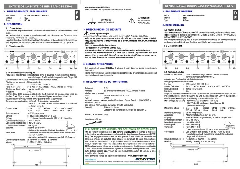
ELC ALE2402R User manual

NOTICE D'UTILISATION DES ALIMENTATIONS
1.RENSEIGNEMENTSPRELIMINAIRES
Constructeur : elc 59, avenue des Romains 74000 ANNECY - FRANCE
Téléphone : 33 (0)4 50 57 30 46 Télécopie : 33 (0)4 50 57 45 19
Instrument : ALIMENTATION REDRESSEE FILTREE D'EQUIPEMENT
Marque : elc
Type : ALE2402R, ALE2405R, ALE2410R.
2.DESCRIPTION
2-1 Présentation
Vous venez d’acquérir une alimentation elc d'équipement, nous vous remercions et vous
félicitons de votre choix.
Cet appareil est destiné aux usages professionnels et industriels.
Le présent manuel d’instruction contient des textes d’informations et d’avertissements qui
doivent être respectés par l’utilisateur pour assurer un fonctionnement sûr et pour maintenir
l’appareil en bon état.
2-2 Vue d’ensemble
2-3 Caractéristiques techniques à 25°C
Tension de sortie : 24 V continu suivant EN 61131-2 ;
TBTS (très basse tension de sécurité) non stabilisée
Ondulation résid. : 5% maxi (voir tableau)
Temps de maintien : 20 ms à tension et intensité nominale
Intensité de sortie : ALE2402R ALE2405R ALE2410R
2,5 A 5.0A 10.0A
Puissance : 60 W 120W 240W
Protections : contre les courts-circuits, par fusible au secondaire
Entrée primaire : 230V/400V 50/60Hz ; possibilité d'adapter la tension de ±15V
Classe d'isolation : I
Indice de Protection : IP30
Degré de pollution : Catégorie de surtension II et degré de pollution 2
Rigidité diélectrique : 4500 VAC, primaire / secondaire ; 2250 VAC, entrée / châssis ;
500 VAC, sortie / châssis.
Conditions : utilisation : + 5 °C à + 55 °C ; stockage : - 25 °C à + 70 °C
d'environnement humidité : de 50 à 95% d'humidité relative.
Dimensions : ALE2402R h = 104 mm l = 80 mm p = 126.5 mm m = 1,9 Kg
Masse ALE2405R h = 125 mm l = 90 mm p = 146.5 mm m = 3,0 Kg
ALE2410R h = 135 mm l = 125 mm p = 156.5 mm m = 4,8 Kg
Présentation : Coffret en tôle acier galvanisée, face avant avec peinture époxy.
Entrée secteur : Bornier à ressort avec levier, pour fils de 1.5 mm².
Connexion de terre : Languette à vis M4 pour fils de 2.5 mm² et "Faston 6.3".
Sortie continue : Bornier à ressort avec levier, pour fils de 2.5 mm²
(doublé sur ALE2410R).
Bornier d'entrée
secteur
Borniers de sortie
LED témoin de
fonctionnement
Fusible
Secondaire
4000 4 324 - 03/14
Languette
de Terre
----------- ALE2402R
----------- ALE2405R
----------- ALE2410R
3. MISE EN SERVICE
3-1 Prescriptions de sécurité
Afin de ne pas compromettre la sécurité de cet appareil, vous devez le raccorder à la terre et l'utiliser conformément
aux instructions de ce document. L'installation de cette alimentation doit être réalisée par du personnel qualifié.
Un disjoncteur de ligne Unipolaire + Neutre de courbe C (1A pour ALE2402R et ALE2405R ; 2A pour ALE2410R)
en réseau monophasé 230V~ ou Bipolaire 400V~ de courbe C (500mA pour ALE2402R ; 1A pour ALE2405R et
ALE2410R), doit être inclus dans l’installation électrique à proximité immédiate de l’appareil et doit être facilement
accessible par l’opérateur.
La tension de mode commun entre la terre et la sortie ne doit pas dépasser 30Vac.
Afin d'éviter les risques de choc électrique, cette alimentation ne doit pas être
accessible en fonctionnement normal. (Ex : installation en armoire ou coffret fermé, ...)
Pour une bonne convection, les appareils sont à installer verticalement. Il est
nécessaire de respecter un espace de 50mm sur tous les cotés et de ne pas masquer
les ouvertures.
3-2 Montage
Fixation par CLIP sur le profilé 35x15mm (rails DIN EN 50022).
Pour limiter la flexion du rail DIN, il est conseillé de positionner l'alimentation proche d'un point
de fixation du profilé. Sur le modèle ALE2410R, deux points seront nécessaires à environ 200mm
de part et d'autre de l'alimentation.
INSTRUCTIONS MANUAL FOR POWER SUPPLIES
1. PRELIMINARY INFORMATIONS
Manufacturer : elc 59, avenue des Romains 74000 Annecy FRANCE
Phone : +33 (0)4 50 57 30 46 Fax : +33 (0)4 50 57 45 19
Product : OEM FILTERED AND RECTIFIED POWER SUPPLY
Brand : elc
Type : ALE2402R, ALE2405R, ALE2410R.
2.DESCRIPTION
2-1 Introduction
You have just purchased an elc OEM power supply. We thank you and congratulate your for
your good choice. This device is intended to professional and industrial uses.
This instructions manual contains informations and warnings the buyer must comply with in
order to ensure safe and sustained operation.
2-2 Overall view
2-3 Technical features at 25°C
Output voltage : 24 V DC according the EN 61131-2
SELV (Toroidal safety transformer) very low safety voltage no regulated
Ripple : 5% max. (see diagram)
Hold up time : 20 ms for nominal voltage and intensity
Output intensity : ALE2402R ALE2405R ALE2410R
2,5 A 5.0A 10.0A
Power : 60 W 120 W 240 W
Protections : against short-circuits by secondary fuse
Main input voltage : 230V/400V 50/60Hz. Possible to adapt the voltage of ±15V
Insulation class : I
Protection index : IP30
Pollution degree : Overvoltage category II and pollution degree 2
Electric strenght : 4500 VAC between primary and secondary
2250 VAC between input and chassis, 500 VAC between input and chassis
Environmental : of use : + 5 °C to + 55 °C
conditions storage : - 25 °C to + 70 °C
moisture : from 50 to 95% of relative moisture
Dimensions : ALE2402R L = 104 mm H = 80 mm D = 126.5 mm W = 1,9 Kg
Weight ALE2405R L = 125 mm H = 90 mm D = 146.5 mm W = 3,0 Kg
ALE2410R L = 135 mm H = 125 mm D = 156.5 mm W = 4,8 Kg
Presentation : Galvanized steel case and front panel with epoxy finish.
Main input voltage : Spring terminal block with leveres, for 1.5 mm² wires.
Earth connection : Screw M4 strip for 2.5 mm² wires and "Faston 6.3".
DC output : Spring terminal block with leveres, for 2.5 mm² wires (double on ALE2410R)
3.WORKING
Main input
voltage
Output plug
Pow er on LED
indicator
Secondary
fuse
Earth strip
----------- ALE2402R
----------- ALE2405R
----------- ALE2410R
4000 4 324 - 04/12
3-1 Safety instructions
The installation of this power supply must be done by qualified people.
The instrument must be used according to the instructions of this manual.
The instrument must be connected to an Earth connection.
An unipolar circuit breaker + Neutral of C curve (1A for ALE2402R and ALE2405R ; 2A for ALE2410R) in 1-phase
230 VAC systems or a two-pole circuit breaker 400 VAC of C curve (500mA for ALE2402R ; 1A for ALE2405R and
ALE2410R), must be included in the electrical installation close to the instrument and must be easily accessible by
the operator.
The common mode voltage between Earth and the output terminals shall not exceed 30 Vac. In order to avoid electric
shocks, this power supply should not be accessible under normal operation.
(Ex : installation in electrical equipment box or closed box...).
For a good convection, the power supply must be installed vertically. It is necessary
to respect a 50 mm space on the sides and not to block the openings.
3-2 Mounting
CLIP fixation on 35x15 mm profiled (DIN rails EN 50022).
To limit the DIN rail inflection, we advise you to put the power supply close to one fixation point
of the profiled.
On the ALE2410R, two points will be necessary at 200 mm from each side of the power supply.
- Engage the two side supports on the top of the rail

Mise en place : engager les crochets sur le haut du rail, pousser l’alimentation contre le
rail, le clip se verrouille ; le repousser si nécessaire.
Pour retirer l’alimentation : introduire un tournevis dans la partie du clip qui dépasse sous
l’alimentation, tirer vers le bas, décrocher l’alimentation en la basculant vers le haut.
Raccordement
Avant toutes connexions, vérifier que le secteur n’est pas présent sur vos fils.
Respecter les branchements du secteur et de la sortie indiqués sur la sérigraphie.
Raccordement primaire :
Entrée en 230V~ sur les bornes sérigraphiées "0" et "230V" ou entrée en 400V~ sur les bornes sérigraphiées "0" et "400V".
Adaptation de la tension d'entrée de ±15V en utilisant les bornes "+15V" ou "-15V" au lieu du "0". (Réseau 220V ou 240V).
Raccorder la terre sur la fiche par la vis M4 ; la languette 6.3mm de cette fiche permet la connexion du "-" de sortie à la terre.
L’utilisation de fils de section faible ou de longueur importante apporte une dégradation des caractéristiques. 3 mètres de fils
1mm² (utilisation à 1.5m de l’alimentation) avec un courant de 2 ampères crée une chute de tension d’environ 100mV.
Il est donc conseillé de ne pas descendre en dessous de cette section et de répartir la puissance sur le modèle ALE2410R
entre les 2 connexions.
4.FONCTIONNEMENT
La diode LED verte éclairée indique la présence de la tension en sortie, donc l'alimentation est en fonctionnement.
Les ALE24xxR sont des alimentations redressées et filtrées. Le taux d'ondulation varie en fonction du courant demandé.
Le tableau ci-dessous vous donne sa valeur, ainsi que la tension moyenne de sortie par rapport aux variations de la charge
appliquée en sortie.
TENSION DE SORTIE 28.3V 26.9V 26.0V 25.3V 24.7V 24.0V
ONDULATION 0% 1% 2% 3% 4% 5%
COURANT ALE2402R 0A 0.5A 1.0A 1.5A 2.0A 2.5A
COURANT ALE2405R 0A 1.0A 2.0A 3.0A 4.0A 5.0A
COURANT ALE2410R 0A 2.0A 4.0A 6.0A 8.0A 10.0A
PROTECTION EN INTENSITE
Si le courant de sortie devient supérieur au courant nominal ou si un court-circuit se produit sur les sorties, le fusible se détériorera.
La diode LED verte sera donc éteinte. Une fois le défaut isolé, remplacer le fusible par le même type et mêmes caractéristiques.
5.MAINTENANCE
Aucun entretien n’est à envisager pour cet appareil.
Eviter la poussière, l’humidité, les chocs, votre appareil vous en sera reconnaissant.
Si le témoin ne s’allume pas à la mise sous tension, vérifier : la présence de tension secteur, le raccordement au réseau, le
fusible secondaire (automobile 5A pour ALE2402R, 10A pour ALE2405R, 20A pour ALE2410R)
6.SERVICE APRES VENTE
Cet appareil est garanti DEUX ANX pièces et main-d’oeuvre contre tous vices de fabrication, les frais de retour sont à la charge
du client. Seuls les appareils retournés avec une facture d’achat datée pourront être couverts par la garantie. Toute intervention
sur l’appareil par des personnes ou organismes non agréés, fait perdre le bénéfice de la garantie.
7. DECLARATION DE CONFORMITE (suivant l'ISO/IEC guide 22 et l'EN45014)
Fabricant : ELC
Adresse : 59 avenue des Romains 74000 Annecy France
déclare que le produit
Nom : Alimentation redressée filtrée
Type : ALE2402R ou ALE2405R ou ALE2410R
est conforme aux spécifications suivantes :
Sécurité : EN 61558-2-6 : 1999
EN 61131-2 : 1994
CEM : EN 61000-6-2:2001, EN 61000-6-4:2001
Informations complémentaires :
Le produit ci-dessus est conforme aux exigences de la Directive Basse Tension 2006/95/CE et de la Directive Compatibilité
Electromagnétique 2004/108/CE.
Annecy, le 08 novembre 2011 H. CURRI Gérant
- Push the power supply against the rail in order to make the plastic clip lock the power supply
(push it back if needed).
To take it off :
- Insert a screwdriver into the part of the clip which appears under the power supply
- Push it towards the bottom
- Take it off rocking towards the top.
Connection
Before any connections, check that the main input voltage is not in your wires.
Respect the connections of the main and of the output indicated on terminal blocks or screenprint.
Primary connection :
230V~ input on the terminal blocks marked "0" and "230V" ; 400V~ input on the terminal blocks marked "0" and"400V"
Possible to adapt the input voltage of ±15V using the "+15V" or "-15V" terminal blocks instead of "0". (220V or 240V mains)
Connect the Earth on the connector by the M4 screw; the 6.3 mm strip of this connector allows the connection of the "-" of
the output to the Earth.
The use of weak section or important length wire leads to a degradation of the characteristics. Three meters of 1mm2wire (used
1.5 meter away from the power supply) with a 2 Amps current make the voltage fall to approximately 100mV. It is thus advised
not to go under this section and to share the power between 2 connections on the ALE2410R.
4.OPERATION
The green LED indicator lighted up shows the presence of the output voltage. The power supply is now working.
The ALE24xxR are filtered and rectified power supplies.
Ripple changes depending on the requested current.
Table below gives you its value and the average output voltage comparing to the load variations of the load applied on the output.
OUTPUT VOLTAGE 28.3V 26.9V 26.0V 25.3V 24.7V 24.0V
RIPPLE 0% 1% 2% 3% 4% 5%
CURRENT ALE2402R 0A 0.5A 1.0A 1.5A 2.0A 2.5A
CURRENT ALE2405R 0A 1.0A 2.0A 3.0A 4.0A 5.0A
CURRENT ALE2410R 0A 2.0A 4.0A 6.0A 8.0A 10.0A
INTENSITY PROTECTION
If the output current becomes superior to the nominal current or if a short-circuit happens on the outputs, the fuse will be
destroyed. The green LED indicator will be switched off.
Once the defect isolated, replace the fuse by one of the same type and same characteristic.
5.MAINTENANCE
No particular maintenance is required for this instrument. Avoid dust, moisture, shocks : your instrument will be grateful for that.
If the green indicator does not light up when switching on, check : the mains voltage, the connection to mains and the secondary
fuse 5A for ALE2402R, 10A for ALE2405R, 20A for ALE2410R.
6. AFTER SALES SERVICE
During TWOYEARS,spare parts and workmanship are guaranteed. This guarantee does not apply to instrument presenting defects
or failures caused by an improper use. Return expenses are borne by the client. Only devices returned with a dated purchasing
invoice can be recovered by the guarantee. Any intervention carried out by unauthorized persons or organizations, shall void
the guarantee.
7. DECLARATION OF CONFORMITY (According ISO/IEC guide 22 and EN45014)
Manufacturer : ELC
Address : 59 avenue des Romains 74000 Annecy FRANCE
declares the product
Name : Filtered and rectified power supply
Type : ALE2402R or ALE2405R or ALE2410R
conformable to the following specifications :
Safety : EN 61558-2-6 : 1999
EN 61131-2 : 1994
EMC : EN 61000-6-2:2001, EN 61000-6-4:2001
Complementary informations :
The product above is conformable to the requirements of the «Low voltage» directive 2006/95/CEE and of the «Electromagnetic
compatibility» directive 2004/108/CEE.
Annecy, November 8th 2011 H. CURRI Manager
ELIMINATION OF MANUFACTURING WASTES BY THE PRIVATE USERS IN THE EU
This symbol written in the product or in its packaging indicates that this product must not be throw in the garbage with your other waste.
Its your responsability to rid of your manufacturing wastes bringing it to a specialized sorting office for the recycling of electrical and electronic
instruments.
Collection and recycling separated of your wastes will contribute to preserve natural resources and guarantee a recycling respectful of the
Environmentandhumanhealth.
For further information concerning the recycling center near your place of residence, contact your town hall, the elimination service of garbage
heap or the store where you bought the instrument.
ELC,OFFREÀSESCLIENTSDESSOLUTIONSDERECYCLAGE
Afin de remplir ses obligations, elc adhère à Récylum et finance la filière de collecte et de recyclage agréée pour les déchets électriques
professionnels (DEEE Pro). Cet engagement volontaire de elc, permet à ses clients de bénéficier de solutions simples et gratuites pour
assurer le recyclage de leurs alimentations électriques, module de secours, générateurs de fonctions et sondes oscilloscopes.
Ainsi, les clients de notre société peuvent se défaire gratuitement de leurs matériels EEE professionnels (désignés précédemment)
usagés. Ils obtiennent, certificat à la clé, l'assurance d'un traitement rigoureux conforme à la règlementation. Il leur suffit de faire appel
à Récylum qui leur indiquera la solution de collecte la plus adaptée à leur besoin.
Pour connaître toutes les solutions de collecte : www.recylum.com
This manual suits for next models
2
Other ELC Power Supply manuals
Popular Power Supply manuals by other brands
Pepperl+Fuchs
Pepperl+Fuchs HiC2027 Series manual
StarTech.com
StarTech.com EPS12V instruction manual
Keysight Technologies
Keysight Technologies E3620A Operating and service manual

CIOKS
CIOKS AC Rider link user manual
Spellman
Spellman uX50P50 instruction manual
NILES ELECTRONICS
NILES ELECTRONICS NEU-4 instruction manual
