manuals.online logo
Brands
  1. Home
  2. •
  3. Brands
  4. •
  5. Electra
  6. •
  7. Intercom System
  8. •
  9. Electra BELLCOME Touch Line User manual

Electra BELLCOME Touch Line User manual

1Safety instructions
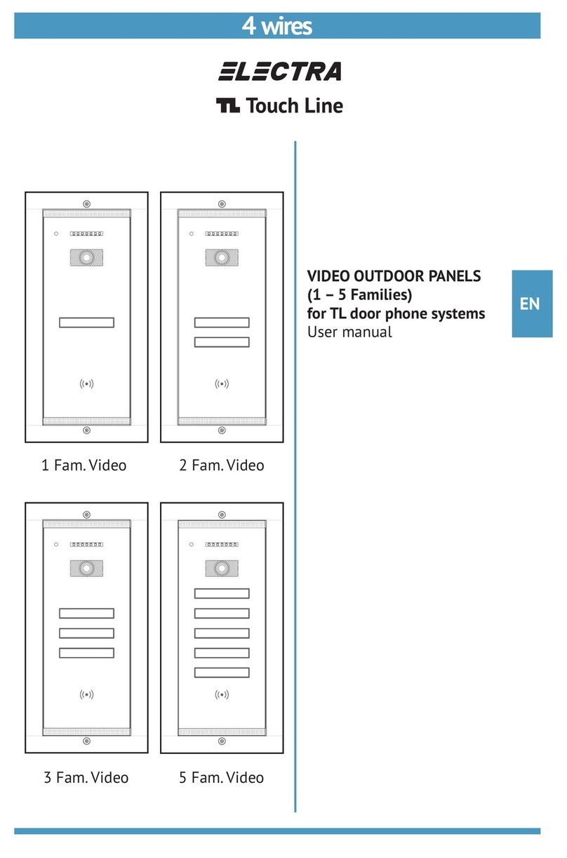
2Description of the Touch Line video panels
DO NOT power the product at 110 – 230 Va.c.!
DO NOT hit the glass screen with hard objects!
If the glass screen is broken, DO NOT touch the product.
Protect the products against lime and dust during renovation activities.
FLUSH mounting SURFACE mounting
0Contents
1Safety instructions
2Description of the Touch Line video panels
4Connection diagrams for 1 – 5 Families
5Connection of additional panels
3Recommended cables.
Installation of the Touch Line video panels.
6Programming and deleting the RFID cards
7Maintenance
8Declaration of conformity. Warranty.
EN
12.1 Technical data
VPA.1FR03.BLB(W)04 VPA.2FR03.BLB(W)04 VPA.1SR03.BLB(W)04 VPA.2SR03.BLB(W)04
VPA.5FR03.BLB(W)04VPA.3FR03.BLB(W)04 VPA.5SR03.BLB(W)04VPA.3SR03.BLB(W)04
294 x 144 x 53 mm 1,52 kg 260 x 110 x 33 mm 1,3 kg
*B = Black; W = White
o o
Aluminium-Case + chemically toughened glass; IP 44; -30 C ... +80 C
CMOS 1.3” 800 TVL video camera
RFID card access
Operating voltage: 11 ... 14 Vd.c.
Stand-by current: 60 mAd.c. Summer / 130 mAd.c. Winter
Operating current: 220 mAd.c. Summer / 300 mAd.c. Winter
EN
2
3Recommended cables. Installation of the Touch Line video panels
3.1 Recommended cables
2.2 Use
Orientable video camera
RFID reader
Microphone
Fastening Torx screw
LEDs (day and night white lighting)
Touch key with the name
of the family
Speaker
Fastening Torx screw
1 Fam. 5 Fam.
2 Fam., 3 Fam.
Fam 2
Fam 1
Fam 3
Fam 4
Fam 5
Fam 1
Presence sensors
LEDs signaling status during use
1. STAND-BY. The keys with the names of the residents are off. The red LED blinks and signals the possibility of
video monitoring.
2. CALL + TALK + ACCESS. The keyboard turns on when a person approaches the panel less than 1m away. Touch
the key corresponding to the name of the family you are looking for. The panel signals the call acoustically, with a beep
sequence and visually – video camera LEDs and LED on.
The call lasts max. 1 min. Each touch of the key reinitiates the call.
If the resident answers, the talk mode is activated – LED on. The conversation is hands-free, with a duration of
max. 2 min. If the resident grants the access, it is commanded the opening of the door/ gate and the panel signals
acoustically, with a confirmation beep sequence and visually – LED on.
The door/ gate remains open max. 8 sec.
3. RFID card ACCESS. Approach the RFID card to the area marked with the symbol. It is commanded the opening of
the door/ gate and the panel signals acoustically, with a confirmation beep sequence and visually – LED on.
The door/ gate remains open max. 8 sec.
Recommended installation cables, based on max. 50 ml distance between the outdoor panel and the
central unit:
UTP/FTP cat5e (AWG24) or UTP/FTP cat6 (AWG23)
C/D
6mm
25-30mm
GND
Vin
+14V+14V
C/D
6mm
25-30mm
GND
Vout
+14
C/D
GND
20-25mm
6mm
Vin
+14
C/D
GND
20-25mm
6mm
Vout
2
4 wires x 0.5 mm (type H03VV-F4G 0.5)
2
4 wires x 0.75 mm (type H05VV-F4G 0.75)
Significance of the connections:
+14V : the (+) connection for power supplying the system components (= 12 14V)
C/D : the connection for audio communication (analog) and digital data transmission (CAN)
GND : the (-) connection for power supplying the system components (GND = 0V)
Vin/Vout : the connection for video signals transmission - PAL/SECAM analog 1Vpp
Example: +14V = red, C/D = blue, GND = black, Vin/Vout = green. Maintain the same colors for the same connections
throughout the system.
Mounting on the wall - Flush
Mounting on the wall - Surface
≈20cm
50mm
120mm
280mm
4mm 50mm
32mm
EN
3
Unmount the module and add the name labels.Mount back the family name module.
Orientation of the video camera
130 cm 130 cm 130 cm
EN
4
Torx
Flush
Torx
Electrical connections in the panel
Torx
Mounting the outdoor panel on the wall
Surface
Important: For both types of mounting, the Torx screws for fastening the outdoor panels on the
wall must be very well tightened, to prevent the anti-theft alarm sensor from setting off.
EN
5
+14
C/D
GND
Vout
Vout
+14
C/D
GND
GNV
GNV
Connection diagrams for 1 – 5 Families
4
Note: Any type of TL terminal can be mounted indoors.
For Fam. 1, the terminal has address 1, which is set by the producer.
The additional terminals mounted in parallel will have the address of the main terminal.
For Fam. 2, the terminal will be programmed with address 2.
See the manual of the TL audio-video terminals.
DVR
1 Family
2 Families
Outdoor Panel
Outdoor Panel
+14
C/D
GND
Vout1
OUTDOOR
110/230Va.c.
50/60Hz
GROUNDED OUTLET
INDOOR
Fam. 2(Address 2)
+14
C/D
GND
Vin
GNG+
GNG-
DBL1
DBL2
Doorbell GONG
Fam. 1(Address 1)
+14
C/D
GND
Vin
GNG+
GNG-
DBL1
DBL2
Doorbell GONG
LOCK
SUPPLY
EXIT
LOCK
max.12Ah/12V
+
-
BAT
+14
C/D
GND
Vout
+14
C/D
GND
Vout
+14
C/D
GND
Vin1
EXT1
EXT2
LCK1
LCK2
-
+
OTHER VIDEO CAMERA DVR AUX1 AUX2 OUT1 OUT2 OUT3
BAT
DOOR LOCK
LOCK
SUPPLY
VIDEO DOOR PANEL
+14
CD
GND
Vin1
GNV
EXIT
EXIT
LCK
LCK
NO NC
10 SEC
BAT
BAT
FUSE - T1.6A
Vout3
GND
CD
+14
Vout2
GND
CD
+14
Vout1
GND
CD
+14
GNV
AUX2
AUX2
AUX1
AUX1
OFF ON
GNV
Vout
+12
GND
Vin2
OFF ON
2 SEC
AC. 110/230V
AUX1
Vcam AUX2
DVR
+14
C/D
GND
Vout1
OUTDOOR
110/230Va.c.
50/60Hz
GROUNDED OUTLET
INDOOR Fam. 1(Address 1)
+14
C/D
GND
Vin
GNG+
GNG-
DBL1
DBL2
Doorbell GONG
LOCK
SUPPLY
EXIT
LOCK
max.12Ah/12V
+
-
BAT
+14
C/D
GND
Vout
+14
C/D
GND
Vin1
EXT1
EXT2
LCK1
LCK2
-
+
AUX1
Vcam AUX2
OTHER VIDEO CAMERA DVR AUX1 AUX2 OUT1 OUT2 OUT3
BAT
DOOR LOCK
LOCK
SUPPLY
VIDEO DOOR PANEL
+14
CD
GND
Vin1
GNV
EXIT
EXIT
LCK
LCK
NO NC
10 SEC
BAT
BAT
FUSE - T1.6A
Vout3
GND
CD
+14
Vout2
GND
CD
+14
Vout1
GND
CD
+14
GNV
AUX2
AUX2
AUX1
AUX1
OFF ON
GNV
Vout
+12
GND
Vin2
OFF ON
2 SEC
AC. 110/230V
SCU.VDR03.BLG14
EN
6
EN
7
3 Families
Note: Any type of TL terminal can be mounted indoors.
For Fam. 1, the terminal has address 1, which is set by the producer.
The additional terminals mounted in parallel will have the address of the main terminal.
For Fam. 2 and Fam. 3, the terminal will be programmed with address 2, respectively address 3.
See the manual of the TL audio-video terminals.
Fam. 3(Address 3)
+14
C/D
GND
Vin
Fam. 2(Address 2)
+14
C/D
GND
Vin
GNG+
GNG-
DBL1
DBL2
Doorbell GONG
Fam. 1(Address 1)
+14
C/D
GND
Vin
GNG+
GNG-
DBL1
DBL2
Doorbell GONG
GNG+
GNG-
DBL1
DBL2
Doorbell GONG
GROUNDED
OUTLET
+14
C/D
GND
Vout
+14
C/D
GND
Vout
+14
C/D
GND
Vin1
+14
C/D
GND
Vout1
OUTDOOR
EXT1
EXT2
LCK1
LCK2
-
+
LOCK
SUPPLY
EXIT
LOCK
INDOOR
max.12Ah/12V
+
-
BAT
OTHER VIDEO CAMERA DVR AUX1 AUX2 OUT1 OUT2 OUT3
BAT
DOOR LOCK
LOCK
SUPPLY
VIDEO DOOR PANEL
+14
CD
GND
Vin1
GNV
EXIT
EXIT
LCK
LCK
NO NC
10 SEC
BAT
BAT
FUSE - T1.6A
Vout3
GND
CD
+14
Vout2
GND
CD
+14
Vout1
GND
CD
+14
GNV
AUX2
AUX2
AUX1
AUX1
OFF ON
GNV
Vout
+12
GND
Vin2
OFF ON
2 SEC
AC. 110/230V
110/230Va.c.
50/60Hz
+14
C/D
GND
Vout
Outdoor Panel
DVR AUX1
Vcam AUX2
Note: Any type of TL terminal can be mounted indoors.
For Fam. 1, the terminal has address 1, which is set by the producer.
The additional terminals mounted in parallel will have the address of the main terminal.
For Fam. 2, 3, 4 and 5, the terminal will be programmed with address 2, respectively addresses 3, 4 and 5.
See the manual of the TL audio-video terminals.
Fam. 5(Address 5)
+14
C/D
GND
Vin
Fam. 3(Address 3)
+14
C/D
GND
Vin
GNG+
GNG-
DBL1
DBL2
Doorbell GONG
Fam. 2(Address 2)
+14
C/D
GND
Vin
GNG+
GNG-
DBL1
DBL2
Doorbell GONG
GNG+
GNG-
DBL1
DBL2
Doorbell GONG
Fam. 4(Address 4)
+14
C/D
GND
Vin
GNG+
GNG-
DBL1
DBL2
Doorbell GONG
Outdoor Panel
OUT 4
OUT 2
OUT 3
OUT 1
OUT
IN
VCB
C/D
GND
Vout
+14
110/230Va.c.
50/60Hz
GROUNDED
OUTLET
+14
C/D
GND
Vin1
+14
C/D
GND
Vout1
OUTDOOR
EXT1
EXT2
LCK1
LCK2
-
+
LOCK
SUPPLY
EXIT
LOCK
INDOOR
max.12Ah/12V
+
-
BAT
OTHER VIDEO CAMERA DVR AUX1 AUX2 OUT1 OUT2 OUT3
BAT
DOOR LOCK
LOCK
SUPPLY
VIDEO DOOR PANEL
+14
CD
GND
Vin1
GNV
EXIT
EXIT
LCK
LCK
NO NC
10 SEC
BAT
BAT
FUSE - T1.6A
Vout3
GND
CD
+14
Vout2
GND
CD
+14
Vout1
GND
CD
+14
GNV
AUX2
AUX2
AUX1
AUX1
OFF ON
GNV
Vout
+12
GND
Vin2
OFF ON
2 SEC
AC. 110/230V
SCU.VDR03.BLG14
+14
C/D
GND
Vin
+14
C/D
GND
Vout
DVR AUX1
Vcam AUX2
EN
8
5 Families
Fam. 1(Address 1)
+14
C/D
GND
Vin
GNG+
GNG-
DBL1
DBL2
Doorbell GONG
Connection of additional panels
5
To one or
more families
C/D
GND
Vout
+14
C/D
GND
Vout
+14
VPA1 (address 1)
110Va.c.
230Va.c.
+14
C/D
GND
Vin
VPA2 (address 2)
+14
C/D
GND
Vin
+14
C/D
GND
Vin
+14
C/D
GND
Vin
110Va.c.
230Va.c.
110Va.c.
230Va.c.
110Va.c.
230Va.c.
C/D
GND
Vout
+14
C/D
GND
Vin
+14
C/D
GND
Vout
+14
C/D
GND
Vout
+14
VSB
12 3 4
C/D
GND
Vout
+14
C/D
GND
Vout
+14
C/D
GND
Vout
+14
C/D
GND
Vout
+14
VPA3 (address 3) VPA4 (address 4)
SCU
PROG
OUT1
+14
SCU.VDR03.BLG34
SCU
PROG
OUT1
+14
SCU.VDR03.BLG34
SCU
PROG
OUT1
+14
SCU.VDR03.BLG34
SCU
PROG
OUT1
+14
SCU.VDR03.BLG34
Important: One VPA video panel and one SCU central unit will be mounted at each entrance.
The programming of the addresses for the panels connected in parallel is done as follows:
a. The VPA1 panel keeps address 1, which is set from the factory.
b. The VPA2 panel with address 2:
Step 1 Long press the PROG button at SCU2 The red LED turns on.
Step 2 Long touch the Fam.1 key at the VPA2 panel Long beep.
Step 3 Short touch the Fam.1 key, twice Two short beeps confirmation.
Step 4 Short touch the PROG button at SCU2 to exit programming mode The red LED turns off.
c. The VPA3 panel with address 3:
Step 1 Long press the PROG button at SCU3 The red LED turns on.
Step 2 Long touch the Fam.1 key at the VPA3 panel Long beep.
Step 3 Short touch the Fam.1 key, three times Three short beeps confirmation.
Step 4 Short touch the PROG button at SCU3 to exit programming mode The red LED turns off.
d. The VPA4 panel with address 4:
Step 1 Long press the PROG button at SCU4 The red LED turns on.
Step 2 Long touch the Fam.1 key at the VPA4 panel Long beep.
Step 3 Short touch the Fam.1 key, four times Four short beeps confirmation.
Step 4 Short touch the PROG button at SCU4 to exit programming mode The red LED turns off.
SCU1 SCU2 SCU3 SCU4
EN
9
Programming and deleting the RFID cards
6
6.1 Manual programming of the RFID cards
When delivered from the factory, the Touch Line video outdoor panels do not have access cards programmed. In order to have
access in the building after installation, it is mandatory to program the RFID cards.
The RFID access cards are programmed at the outdoor panel, separately for each family and will be stored in the EEPROM
memory of the system central unit (SCU). Maximum 20 cards can be programmed for each family. The programming procedure
is the following:
The entire video door system is installed and set under tension.
0
1 Go to the place where the SCU central unit of the installation is mounted.
Long press (2-3 sec.) the PROG button The red LED turns on.
2
Return to the oudoor panel with the RFID cards allocated separately for each family.
Cards programming for Fam. 1:
- Long press (2-3 sec.) the Fam. 1 key Long beep.
- Briefly approach every card to the area marked with . For each programmed card, the panel
issues two short beeps.
- After storing all the cards for Fam. 1, to end the programming for the respective family, short touch the
next family key Three short beeps confirmation.
*For 1 Fam. panels, go to step 3.
Cards programming for Fam. 2:
- Long press (2-3 sec.) the Fam. 2 key Long beep.
- Briefly approach every card to the area marked with . For each programmed card, the panel issues
two short beeps.
- After storing all the cards for Fam. 2, to end the programming for the respective family, short touch the
next family key Three short beeps confirmation.
Repeat the same steps for Fam. 3, Fam. 4, Fam. 5, etc.
3 Go back to the place where the SCU central unit of the installation is mounted.
Short touch the PROG button The red LED turns off.
Note 1: Follow the same procedure for subsequent programming: card additions or changes.
6.2 Deleting the RFID cards
The cards are deleted separately for each family. The deletion procedure is the following:
The video door system is functional, set under tension.
0
1 Go to the place where the SCU central unit of the installation is mounted.
Long press (2-3 sec.) the PROG button The red LED turns on.
2
Cards deleting for Fam. 1:
- Long press (2-3 sec.) the Fam. 1 key Long beep.
- Short touch the Fam. 1 key seven times Two short beeps confirmation.
- Long press (2-3 sec.) the Fam. 1 key Long beep.
Cards deleting for Fam. 2:
- L ong press (2-3 sec.) the Fam. 2 key Long beep.
- Short touch the Fam. 2 key seven times Two short beeps confirmation.
- Long press (2-3 sec.) the Fam. 2 key Long beep.
Repeat the same steps for Fam. 3, Fam. 4, Fam. 5, etc.
3 Go back to the place where the SCU central unit of the installation is mounted.
Short touch the PROG button The red LED turns off.
Note 2: The SCU central unit automatically exits the programming mode, after 5 min. from the last programming action.
EN
10
EN
11
The Touch Line outdoor panels must be kept away from corrosive substances, lime and blows.
For cleaning the glass screens, use a clean cloth and a solution for glass washing.
In case of renovation activities, the Touch Line video door system components must be completely protected with plastic foil.
DO NOT undo the electrical connections of the Touch Line video door system components.
DO NOT short-circuit the electrical connections of the Touch Line video door system components.
The manufacturer ELECTRA s.r.l. declares that:
The products are in compliance with the harmonized legislation of the European Union regarding the directives:
Low Voltage (LVD) 2014/35; Electromagnetic compatibility (EMC) 2014/30/EC; RoHS 2011/65/EC.
The following harmonised standards and technical specifications have been applied: SR EN 60950-1:2006 + A1:2011
+ A2:2014 + A11:2009 + A12:2014 + AC:2011 + C91:2010; SR EN 55022:2011 + AC:2011; SR EN 55024:2011 + A1:2015;
SR EN 61000-3-2 2015; SR EN 61000-3-3:2014.
The products do not threaten life, health, work safety, do not have any negative effect on the environment and have been
produced under the ISO 9001:2015/ ISO 14001:2015 Quality and Environment Management System certified by
TÜV HESSEN.
Warranty
1. A 24-month warranty is granted, according to the existing legislation, based on the purchase document.
2. Warranty is granted for non-conformity and/or hidden defects.
3. Warranty is NOT granted for:
- Missing purchase documents;
- Incorrect installation, non-compliant with this manual (e.g.: wrong supply voltage);
- Incorrect operation, non-compliant with this manual (e.g.: wrong settings);
- Broken glass and/or other damage, blows, mechanical shocks;
- Theft, fire, floods, natural disasters;
- Unprotected product during renovation activities;
- Use of the product in systems that require different performance parameters from the ones provided by the technical
specifications in this manual;
- The RFID access cards (tags), which are considered consumables.
4. For complaints during the warranty period, please contact the company from which you have purchased the product.
8Declaration of conformity. Warranty.
7Maintenance
03.2021 USM.VPA.5XR03.BLY04
Certificate no. E307311
ISO 9001:2015
ISO 14001:2015
Certificates no. 73 100 4856, 73 104 4856
by TÜV HESSEN
The products are manufactured under
Quality and Environment Management System
The products are
CE certified.
R
The products contain UL-compliant
printed circuit boards.
Certificate by
R709 ICPE
BELLCOME is a trademark of ELECTRA Group - No. 013502646 - EUIPO - Alicante, Spain
BELLCOME/ELECTRA products are registered as Industrial Models - EUIPO - Alicante, Spain
Designed and produced by ELECTRA
SUPPORT
ELECTRA Building Communications GmbH
Bischoffgasse 5/3-4,
1120 Wien - AT
+43 1 810 20 99
[email protected]
www.bellcome.com
MADE in EU by:
ELECTRA s.r.l
Parc Industrial Miroslava
Str. Principala 33, 707307, Jud. Iași - RO
+40 232 214.370
[email protected]
www.electra.ro

Other Electra Intercom System manuals

Electra Touch Line Series User manual

Electra

Electra Touch Line Series User manual

Electra APE.1S1.x&x User manual

Electra

Electra APE.1S1.x&x User manual

Electra SMART+ series User manual

Electra

Electra SMART+ series User manual

Electra evolution User manual

Electra

Electra evolution User manual

Electra ATM.0S042 User manual

Electra

Electra ATM.0S042 User manual

Electra SMART+ User manual

Electra

Electra SMART+ User manual

Electra KIT AUDIO DOOR PHONE basic1 family User manual

Electra

Electra KIT AUDIO DOOR PHONE basic1 family User manual

Electra APE.2S1.x&x User manual

Electra

Electra APE.2S1.x&x User manual

Electra Basic TL User manual

Electra

Electra Basic TL User manual

Electra VPM.1FR02 User manual

Electra

Electra VPM.1FR02 User manual

Popular Intercom System manuals by other brands

urmet domus 1083/12 Configuration guide

urmet domus

urmet domus 1083/12 Configuration guide

Fermax NCITY 1-2L User& installer's manual

Fermax

Fermax NCITY 1-2L User& installer's manual

Bpt YC/300 installation instructions

Bpt

Bpt YC/300 installation instructions

Bpt VILLASET HP-YC Series installation instructions

Bpt

Bpt VILLASET HP-YC Series installation instructions

MOBILE INTERCOM RI-32 user manual

MOBILE INTERCOM

MOBILE INTERCOM RI-32 user manual

System Q Door Knox VDP304 instruction manual

System Q

System Q Door Knox VDP304 instruction manual

SSS Siedle HTSV 811-0 installation instructions

SSS Siedle

SSS Siedle HTSV 811-0 installation instructions

Aiphone DB-1SD Operation manual

Aiphone

Aiphone DB-1SD Operation manual

LEGRAND 0 416 51 quick start guide

LEGRAND

LEGRAND 0 416 51 quick start guide

Comelit Simplebus Color 4888C Technical sheet

Comelit

Comelit Simplebus Color 4888C Technical sheet

Farfisa KM862W manual

Farfisa

Farfisa KM862W manual

Bpt HEV/300-302 VR installation instructions

Bpt

Bpt HEV/300-302 VR installation instructions

Aiphone IXG Series Quick start programming guide

Aiphone

Aiphone IXG Series Quick start programming guide

Aiphone JK-DVF-AC Installation & operation manual

Aiphone

Aiphone JK-DVF-AC Installation & operation manual

urmet domus Audio Two Technical manual

urmet domus

urmet domus Audio Two Technical manual

Aiphone IC-DC instructions

Aiphone

Aiphone IC-DC instructions

ACT ACTSMART STANDALONE - INSTALLATION DIAGRAM Installation

ACT

ACT ACTSMART STANDALONE - INSTALLATION DIAGRAM Installation

Bell System DAX manual

Bell System

Bell System DAX manual

manuals.online logo
manuals.online logoBrands
  • About & Mission
  • Contact us
  • Privacy Policy
  • Terms and Conditions

Copyright 2025 Manuals.Online. All Rights Reserved.