manuals.online logo
Brands
  1. Home
  2. •
  3. Brands
  4. •
  5. elero
  6. •
  7. Transmitter
  8. •
  9. elero Aero-915 User manual

elero Aero-915 User manual

Aero-915/Aero-915 Plus Operating instructions
28 440.0002/28 480.0001
Warning!
Important safety instructions!
Observe the following instructions.
• Only use unmodified original
elero
electrical parts.
• Keep persons away from the operating range of the
system.
• Keep children away from the controls.
• Follow the relevant country-specific regulations.
• If one or more devices are used for controlling the
system, the operating range must stay visible during
operation.
• The device contains swallowable small parts.
• Up- or downwinds blowing against façades may
cause destruction of equipment.
• The Aero-915/Aero-915 Plus is
not
able to recognise
these.
• Please pay attention to this advice when choosing
your mounting position.
General information
Aero-915 is a wireless sun/wind control device for your awning.
Integrated solar cells enable autonomous function of the device.
Radio signals (frequency 915 MHz) are transmitted between the
Aero-915 and the receiver.
Important!
The Aero-915/Aero-915 Plus only operates in connection with radio
receivers of the elero ProLine-915 radio system.
Special features of the Aero-915 Plus
The Aero-915 Plus is equipped with an additional energy store and
an additional solar cell. The standby-time is 14 hours.
The awning can be operated manually via a manual/wall trans-
mitter. This item is not included in the scope of delivery.
Recommendation:
Use a LumeroTel or VarioTelPlus manual trans-
mitter in connection with the Aero-915/Aero-915
Plus to deactivate the sun function.
Safety instructions
b
b
v
b
b
80
200
135
b
b
35
b
b
66
Intended use
The Aero-915 AC may only be used for control of awnings and
venetian blind installations.
Third-party devices should only be connected after consultation
with your specialised dealer.
•Please ensure that the radio installations are not operated in
areas of heightened possible interference. (e.g. hospitals,
airports…).
•The remote control is only approved for devices and systems for
which any malfunction of the manual transmitter or receiver
would not result in a risk for persons, animals or property, or if
such a risk is covered by other safety devices.
•The operator has no protection whatsoever from interferences
by other radio emitters and local terminals (e.g. also from radio
installations), that are normally used on the same frequency
range.
•Only use radio receivers with equipment and units approved by
the manufacturer.
10
12
14
2
Off
8
4
6
11
1
3
9
5
7
yellow LED
(light value) red LED
(Wind value)
green LED
(transmit)
DOWN
button
(Sun symbol)
UP button
(Wind symbol)
USA
CA
Instruction to the user
This equipment has been tested and found to comply with the
limits for a class B digital device, pursuant to part 15 of the FCC
Rules. These limits are designed to provide reasonable protection
against harmful interference in a residential installation. This
equipment generates, uses and can radiate radio frequency ener-
gy and if not installed and used in accordance with the instruc-
tions, may cause harmful interference to radio communications.
However, there is no guarantee that interference will not occur in
a particular installation. If this equipment does cause harmful
interference to radio or television reception, which can be
determined by turning the equipment off and on, the user is
encouraged to try to correct the interference by one or more of
the following measures:
•Reorient or relocate the receiving antenna.
•Increase the separation between the equipment and receiver.
•Connect the equipment into an outlet on a circuit different from
that to which the receiver is connected.
•Consult the dealer or an experienced radio/TV technician for
help.
Operation with non-approved equipment is likely to result in
interference to radio and TV reception. The user is cautioned that
changes and modifications made to the equipment without the
approval of manufacturer could void the user's authority to
operate this equipment.
2
Function for "Auto" switch setting (manual transmitter)
The
UP-STOP-DOWN
button on the manual transmitter and the
UP/DOWN
keys at the Aero-915 are active.
–Wind monitoring is active
–Sun protection is active.
Semi-automatic mode
Your Aero-915/Aero-915 Plus is in AUTO mode.
As soon as you now press a button on your programmed manual
transmitter the receiver switches itself into the semi-automatic
mode.
Leave semi-automatic mode:
–If a level falls below and/or rises above a set threshold value then
the system automatically changes to AUTO mode.
The system moves in/out.
or
–Set the sliding switch of your transmitter briefly to
MANUAL mode and then to AUTO mode.
The system moves in.
Loading the Aero-915/Aero-915 Plus
The Aero-915 is supplied in discharged condition.
1. Prior to commissioning, load the Aero-915 for at least minimum 30
minutes under a lamp or press a travel key for at least 1 minute.
Advice:
the travel keys have two settings.
The first setting transfers energy from a built-in cell to the energy
store.
The second setting activates the travel command.
Programming the Aero-915/Aero-915 Plus
Condition: The end positions of the awing are set, a transmitter is
programmed.
Start teach mode
1. Blind/shutter
runs up and
down for
2minutes.
min. 3 sec.
elero
2.
3.
STOP
STOP
Press the ”UP”
(wind symbol)
button imme-
diately after the
start of upward
travel .
Press the ”DOWN”
(sun symbol)
button immedia-
tely after the start
of downward
travel.
"Teach-in" programmed
transmitter.
10
12
14
2
Off
8
4
6
11
1
3
9
5
7
10
12
14
2
Off
8
4
6
11
1
3
9
5
7
Setting the threshold values
Multiple contact switches for wind and sun are located at the
underside of the Aero-915. The switch has several settings, which
can be modified with a small screwdriver..
Wind
Setting 1 ➯Retract at low wind speed
Setting 2 bis 10 ➯Intermediate levels
Setting 4 ➯Factory setting
Setting 11 ➯Retract at high wind speeds
Sun
Setting OFF ➯Light function is deactivated
Setting 1 ➯Move out at low light levels
Setting 2 bis 13 ➯Intermediate levels
Setting 4 ➯Factory setting
Setting 14 ➯Move out in full sun
11
1
3
9
5
7
10
12
14
2
Off
8
4
6
red LED
yellow LED
Function for "Manual" switch setting (manual transmitter)
The UP-STOP-DOWN button on the manual transmitter and the
UP/DOWN keys at the Aero-915 are active.
–Wind monitoring is active
–Sun protection is disabled.
Device function
Light intensity and wind speed are measured at regular intervals
and compared with the set values.
Brightness above set value
➩
Awning moves out after delay time
(Delay time approx. 5 min.) (yellow LED winks).
Brightness below set value
➩
Awning retracts after delay time or
(Delay time approx. 15 min.) remains retracted .
Wind value above set value
➩
Awning retracts or remains retracted
and is blocked for around 15 min.
(red LED flashes)
The slide switch at the taught manual transmitter can be used to
switch the light function of the Aero-915 AC on or off. The wind
function is always active, irrespective of the light switch setting.
The slide switch has no influence on the function of the travel keys.
However, in the event of a wind alarm, the keys are disabled for
15 minutes.
3
a
Wall bracket
rotated 90°
Wall bracket
rotated 180°
Mast and corner bracket
(Aero, Aero-915/Aero-915 Plus)
Optional accessory
(Article no. 24 269,0201)
Caution!
Up- or downwinds blowing against façades may
cause destruction of equipment.
The Aero-915/Aero-915 Plus is not able to recognise
these.
Please pay attention to this advice when choosing
your mounting position.
Deleting programmed Aero-915/Aero-915 Plus
The Aero-915/Aero-915 Plus is deleted from the receiver.
1.
Press the
UP
/
and the
DOWN
buttons
simul-
taneously
.
10
12
14
2
Off
8
4
6
11
1
3
9
5
7
Green LED
(transmit)
goes out
briefly.
min. 3 sec.
Mounting options for Aero-915/Aero-915 Plus
The wall bracket can be swivelled between –5° and 180°.
Secure the required position once it has been set (see screw a).
Check the sun protection function (test mode)
Condition: The blind/shutter is retracted.
The delay times are shortened in the test mode. You can then test
the travel movement of your system on the set light value being
exceeded or undercut.
1. Press the UP button (wind symbol) for at least 3 seconds until
the green LED flashes.
The test mode stays active for 5 minutes but with the LED
extinguished.
2. Shine a torch on the sun sensor.
Set light value is exceede Wshutter/blind immediately travels
out/down.
Light value has reached/exceeded the set threshold value W
yellow LED flashes.
Set light value is undercut Wshutter/blind travels in/up after
15 seconds.
You can repeat the operation as often as you want within
5 minutes.
In "normal" operation the LEDs light up every 5 seconds and show
that the threshold values have been reached or exceeded.
Warning!
Injury risk from extending the awning or running
down the venetian blind
The test mode is active for 5 minutes. This time
cannot be shortened.
Keep away from the operating range of the system.
Check the wind function (test mode)
Condition: The blind/shutter is retracted.
The delay times are shortened in the test mode. You can then test
the travel movement of your system on the set wind value being
exceeded or undercut.
During the test phase the set wind value is automatically set to the
lowest value and re-set once the test phase (5 minutes) is over.
1. Press the UP button (wind symbol) for at least 3 seconds until
the green LED flashes.
The test mode stays active for 5 minutes but with the LED
extinguished.
2. Use the hand transmitter to bring the shutter/blind to the
centre position.
3. Turn the wind vane.
The shutter/blind travels in/up immediately.
Set wind value is exceeded/undercut Wred LED flashes.
You can repeat the operation as often as you want within
5 minutes.
Note: In the event of a wind alarm, the travel keys are disabled for
15 seconds.
In "normal" operation the LEDs light up every 5 seconds and show
that the threshold values have been reached or exceeded.
Warning!
Injury risk from extending the awning or running
down the venetian blind
The test mode is active for 5 minutes. This time
cannot be shortened.
Keep away from the operating range of the system.
Installation
Before installing the unit at the required position, check the
proper function of the Aero-915 and the receiver.
Maintenance
The Aero-915/Aero-915 Plus is maintenance-free, but the cover
must be cleaned from time to time.
Techncal Data
Power supply Solar
Temperature range –25 °C to +60 °C
Detection angle (light sensor) 150°
Protection class IP 43
Radio frequency 915 MHz
Standby Aero-915 ~ 8 hrs.
Standby Aero-915 Plus ~ 16 hrs.
Fault Cause Remedy
• Awning automa-
tically retracts in
manual mode
• No travel
command can
be issued via the
manual trans-
mitter
• Awning does not
retract in windy
conditions
• Awning does not
move out in
sunny conditions
• Receiver does
not accept
Aero-915/
Aero-915 Plus
• Wind alarm
• Poor radio connection
• Wind alarm is active
• Battery in the manual
transmitter is dead
• Motor has no power
supply or is overheated
• Wind threshold value is
set incorrectly
• Wind vane is faulty
• Threshold set incorrectly
• Wind alarm is still active
• Manual mode is set
• Poor radio connection
• Sun sensor is dirty
• SUN threshold value
(OFF setting)
• Aero-915/Aero-915 Plus
is already programmed.
•Wait for wind interlock
to be deactivated
(15 min.) or briefly
interrupt power supply.
•Change the position of
the Aero-915/
Aero-915 Plus
•Wait (15 minutes)
•Change battery
•Check power supply or
allow motor to cool
down.
•Set correct value
•Replace
•Set correct value
•Wait
•Set automatic mode
•Change the position of
the Aero-915/
Aero-915 Plus
•Clean sun sensor
•Set appropriate setting
•Delete Aero-915/
Aero-915 Plus.
20 18 100.6501
We reserve the right to make technical changes 06/06
20
elero USA
10827 Alder Circle
Dallas, Texas 75238
Tel. (1) 214/343-1676
Fax (1) 214/342-8528 [email protected]
www.eleroUSA.com
a
Wall bracket
rotated 90°
Wall bracket
rotated 180°
Mast and corner bracket
(Aero, Aero-915/Aero-915 Plus)
Optional accessory
(Article no. 24 269,0201)
Mounting options for Aero-915/Aero-915 Plus
The wall bracket can be swivelled between –5° and 180°.
Secure the required position once it has been set (see screw a).

This manual suits for next models

1

Other elero Transmitter manuals

elero LumeroTel 2 User manual

elero

elero LumeroTel 2 User manual

elero LumeroTel-915 User manual

elero

elero LumeroTel-915 User manual

elero TempoTel 2 User manual

elero

elero TempoTel 2 User manual

elero LumeroTel User manual

elero

elero LumeroTel User manual

elero TempoTel 2 User manual

elero

elero TempoTel 2 User manual

elero COM Series Specification sheet

elero

elero COM Series Specification sheet

elero MemoTec-915 User manual

elero

elero MemoTec-915 User manual

elero MultiTec Touch-868 User manual

elero

elero MultiTec Touch-868 User manual

elero Invio-868 User manual

elero

elero Invio-868 User manual

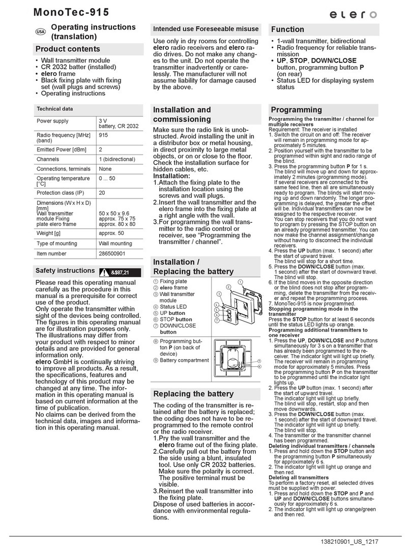
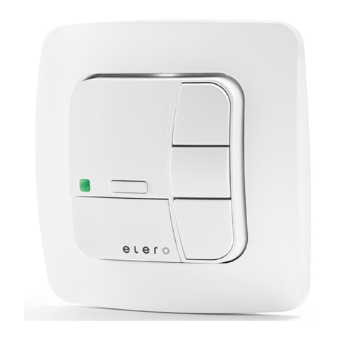
elero MonoTec-915 User manual

elero

elero MonoTec-915 User manual

elero monotel 2 28 205.0001 User manual

elero

elero monotel 2 28 205.0001 User manual

elero UniTec-868 User manual

elero

elero UniTec-868 User manual

elero VarioTel-915 User manual

elero

elero VarioTel-915 User manual

elero UniTec-868 User manual

elero

elero UniTec-868 User manual

elero MonoTel-915 User manual

elero

elero MonoTel-915 User manual

elero COM Series Specification sheet

elero

elero COM Series Specification sheet

elero Invio-915 User manual

elero

elero Invio-915 User manual

elero UniTec-868 User manual

elero

elero UniTec-868 User manual

elero TempoTel 2 User manual

elero

elero TempoTel 2 User manual

elero VarioCom Slide 915 Guide

elero

elero VarioCom Slide 915 Guide

elero TempoTel 28 260.0001 User manual

elero

elero TempoTel 28 260.0001 User manual

elero VarioTel User manual

elero

elero VarioTel User manual

Popular Transmitter manuals by other brands

Inovonics EN1212 installation instructions

Inovonics

Inovonics EN1212 installation instructions

Rose electronics UltraLink E Series Installation and operation manual

Rose electronics

Rose electronics UltraLink E Series Installation and operation manual

Evikon E2615 Series user manual

Evikon

Evikon E2615 Series user manual

DRAKE T-4XC instruction manual

DRAKE

DRAKE T-4XC instruction manual

M-system 17PE instruction manual

M-system

M-system 17PE instruction manual

WisyCom MTP40S-US user manual

WisyCom

WisyCom MTP40S-US user manual

ENMET EX-5120 manual

ENMET

ENMET EX-5120 manual

Canon WFT-R10 Advanced user's guide

Canon

Canon WFT-R10 Advanced user's guide

DAPAudio EB-16 manual

DAPAudio

DAPAudio EB-16 manual

SMART-AVI VCA100 user manual

SMART-AVI

SMART-AVI VCA100 user manual

SABINE SW70-T Quick setup guide

SABINE

SABINE SW70-T Quick setup guide

Nautel XR3 installation manual

Nautel

Nautel XR3 installation manual

Tekkeon myPower FM MP1100-50 user guide

Tekkeon

Tekkeon myPower FM MP1100-50 user guide

Ezodo 4803P manual

Ezodo

Ezodo 4803P manual

Valcom T72 Series manual

Valcom

Valcom T72 Series manual

Erreka IRIS IR02 quick start guide

Erreka

Erreka IRIS IR02 quick start guide

TEWTROSS BTA003 manual

TEWTROSS

TEWTROSS BTA003 manual

Electro-Voice REV-BP user manual

Electro-Voice

Electro-Voice REV-BP user manual

manuals.online logo
manuals.online logoBrands
  • About & Mission
  • Contact us
  • Privacy Policy
  • Terms and Conditions

Copyright 2025 Manuals.Online. All Rights Reserved.