manuals.online logo
Brands
  1. Home
  2. •
  3. Brands
  4. •
  5. Elite Greenhouses
  6. •
  7. Greenhouse Kit
  8. •
  9. Elite Greenhouses GX800 User manual

Elite Greenhouses GX800 User manual

PARTS LIST
6X8 8X8 10X8 12X8 14X8 16X8 18X8 20X8
Ridge 1 1 1 1 1 1 1 1
Gutter/Eave 2 2 2 2 2 2 2 2
Side Cill 2 2 2 2 2 2 2 2
Diagonal Side Braces 4 4 4 4 6 8 8 8
Door End Block Glazing Bar 2 2 2 2 2 2 2 2
Door End Ramp Cill 1 1 1 1 1 1 1 1
Door End Cill 1 1 1 1 1 1 1 1
Door End Diagonal Angle 2 2 2 2 2 2 2 2
Door End Small Horizontal Angle 2 2 2 2 2 2 2 2
Glazing Bar Over Double Door 1 1 1 1 1 1 1 1
Small Door Track Support 2 2 2 2 2 2 2 2
Short Rear End Glazing Bar 2 2 2 2 2 2 2 2
Rear End Block Glazing Bar 2 2 2 2 2 2 2 2
Rear End Cill 1 1 1 1 1 1 1 1
Rear End Horizontal Angle 1 1 1 1 1 1 1 1
Rear End Diagonal Angle 2 2 2 2 2 2 2 2
Corner bars in 2 packs of 4 8 8 8 8 8 8 8 8
Roof Bars 3 4 6 8 8 10 10 12
Side Bars 4 6 8 10 12 14 16 18
Short Roof Glazing Bar 1 2 2 2 4 4 6 6
Roof Hanging Basket Rail 2 2 2 2 2 2 2 2
Roof Vent Pack 1 2 2 2 4 4 6 6
Door Panel Pack (made up of 1 top
panel, 1 bottom panel and 3 inter-
mediate panels)
2 2 2 2 2 2 2 2
Door Track Support 1 1 1 1 1 1 1 1
Top Door Track 1 1 1 1 1 1 1 1
Door Post Pack (made up of 2 handed
and 2 unhanded) 1 1 1 1 1 1 1 1
Cantilever T-Bar Brace 6 9 12 15 18 21 24 27
5 Blade Louvre 2 2 2 2 2 2 2 2
8’Diamond Shelf 1 1 1 1 1 1 1 1
Bar Capping Pack 1 1 1 1 1 1 1 1
Bag of Fitiings 1 1 1 1 1 1 1 1
Draught Excluders 2 2 2 2 2 2 2 2
Glazing Beading 300’300’350’400’400’450’500’550’
Gusset Plates—Eaves
4 4 4 4 4 4 4 4
Gusset Plates—Ridge 2 2 2 2 2 2 2 2
Casement Stays 2 4 4 4 8 8 12 12
Glass—see plan at back of book
Base Preparation
If you are constructing the greenhouse on a patio, flagged or concrete area you can utilise
the angle brackets which are provided and illustrated later in this booklet under heading
‘securing down’.
If you are building a concrete footing you would still anchor down as indicated above but
would build your wall/footing to the following dimensions.
These are exterior measurements and the outside edge of the cill will be level with the
outside of the brick.
If you are constructing on soft standing e.g. soil or lawn you will need to purchase special
anchor brackets that you would concrete into the ground and bolt onto the cill and upright
glazing bars. Concreting of these brackets into the ground is one of the last jobs of the
construction process.
HELPFUL HINTS
·
Tools required:
Spanners (M6 x M4 Bolts)
Screwdriver (posi drive)
Pliers
Drill
Hacksaw
Ladders
For Glazing –Gloves / Goggles/glasses
·
Please do take your time and be sure to read all instructions carefully before assem-
bling.
·
Do not assemble frame in high winds.
·
The greenhouse frame should be anchored to a permanent foundation. This will not
only help secure it against powerful winds, but will help prevent breakage of the glass
caused by the freezing and thawing process of the earth. (Key point).
Nominal size Width Length √
6x8 2.586 1.987 3.261
8x8 2.586 2.605 3.671
10x8 2.586 3.223 4.132
12x8 2.586 3.842 4.630
14x8 2.586 4.459 5.155
16x8 2.586 5.077 5.698
18x8 2.586 5.695 6.255
20x8 2.586 6.313 6.822
·
When building your own brick/concrete foundations ensure that they are level and
square otherwise your frame will not be correct and the glass will not fit.
·
Be sure all four corners of the constructed greenhouse are square before installing
glass, and do not install the glass until the greenhouse is on a permanent foundation.
·
Do not place your greenhouse in vulnerable locations such as under trees, playing
areas etc.
·
Children should not play near glass greenhouses.
·
REMEMBER: Glass is fragile, handle with extreme care! (Key point).
·
Protective clothing such as gloves, strong outer clothing and eye glasses should be
worn.
·
Be careful when using agricultural chemicals such as fertilisers, fungicides and insec-
ticide etc. in the greenhouse. Do not use chemicals that are for outside use only. Al-
ways read the labels very carefully.
·
Do not push or lean on the glass panels.
·
Use extra care when moving heavy or awkward objects such as tables, poles, inter-
nal frames etc. within or near the greenhouse.
·
Do not latch the door when anybody is inside the greenhouse.
·
Be aware of the increased temperature in a greenhouse on a sunny day.
·
Do not keep pets or other animals in a greenhouse.
·
When cleaning glass, do not exert too much pressure.
·
If your greenhouse is painted there are a few 3mm holes in the ends of some bars.
These are jig holes for the painting and have no bearing on the construction. (Key
point)
·
WHEN CONSTRUCTING A PAINTED MODEL PLEASE TAKE CARE NOT TO DAM-
AGE THE FINISH BY WORKING ON CONCRETE OR PATIOS.
·
N.B. This plan covers the entire GX800 range. The only difference between a 6’long
and an 8’long for example are a few extra pieces of alloy, glass, nuts and bolts etc.
The constructions of the sub-frame assemblies are the same but for the purposes of
this booklet we have used the 12 x 8 model as the benchmark. Therefore only one
plan is needed.
DETAILED ASSEMBLY INSTRUCTIONS
The contents of these packages are divided into the different frame assemblies that
collectively make up the completed greenhouse framework.
It is recommended that each frame assembly is fully completed before moving on to the
next.
The frames to be constructed are as follows:
1. Side frames –two off
2. Rear end frame –one off
3. Door end frame –one off
4. Roof vent (quantity dependent upon length)
5. Door –two off 2’0”wide
6. Additional parts such as the ridge, roof bars, eave ties, cantilevers etc. are put on
loose and are not pre-constructed into an independent frame. The partition, if appropriate
is constructed in situ and not as an independent frame, see page 28.
WE CAN NOW COMMENCE WITH THE ASSEMBLY
SIDE FRAME ASSEMBLY
From the main box you require: pack of side glazing bars marked ‘side bars’, pack of gut-
ters, angles and cills marked ‘side’.
From the pack of fittings you need: nuts and bolts and glazing beading.
PROCEDURE: For the point of this plan we have used a 12 x 8 side as an illustration. The
procedure is identical for a 6 x 8 up to a 20 x 8 apart from an alteration of more or less side
bars, nuts and bolts, glazing beading and longer or shorter gutters and cills. (Key point).
If you have purchased a partition with your greenhouse you will have 2 less roof and 2
less side glazing bars. These are replaced with an extra set of corner bars. You must de-
cide where the partition is to be situated and at that point leave out one side bar on each
of the side frames. (Key point). The partition is constructed when the greenhouse is fully
erected prior to glazing. Full details of this procedure given later on pages 28 + 29 but for
the time being, do nothing apart from the omission of the side bar. If you have not pur-
chased a partition disregard this and future notes relating thereto.
You need for each side frame:
1 gutter/eaves, 1 alloy cill, 2 diagonal angles
and 5 side bars. For other sizes please refer to
parts list at front of booklet for quantities.
Layout the component parts on the ground as though you were standing on the inside of a
completed greenhouse i.e. with the bolt slots uppermost.
1. Slide the glazing beading into both sides of each side glazing bar tak-
ing care not to stretch the material. Trim off any surplus level with the
ends of the glazing bars.
2. Lay the 9 components onto the floor as though you were standing inside the green-
house i.e. with the gutter and cill facing downwards and the bolt slot of the glazing bar
upwards. (Key point). Remember for 14’, 16’x 18’and 20’lengths there are extra glaz-
ing bars and angles.
3. Before assembling any sections, slide the required number of bolts into the glazing
bars. You must decide the position of the louvre. The 2 standard louvres can be fitted
on either side of the greenhouse (except where a side diagonal brace intersects the
bay) or in the centre bay at the rear end. The louvre is fitted during glazing. Once decid-
ed, slide 4 bolts (2 per bar) into the glazing bars onto which the louvre will be attached.
If you have ordered Diamond Staging to be fitted to the side of your greenhouse, you
will need to insert 2 extra bolts into each glazing bar that the staging will cover. These
bolts will be used later in the booklet. (See staging instruction).
4. In addition to louvre and staging bolt requirement, slide 3 bolts into each glazing bar, the
middle bolt will be used later to attach the cantilever tee bars (remember louvre bolts).
Fix the combined eaves and gutter bars to the glazing bars by pushing the bolt previ-
ously inserted through the holes in the lower flange of the eave and secure with a nut.
Ensure that the glazing bar is pushed up under the gutter and is tight up against the in-
side shoulder of the eave. (Key Point). Do the same with the rest of the glazing bars.
5. Fix the cill in a similar way to 3 above, but start with the middle glazing bars and work
outwards.
6. The 2 outer glazing bars have the angle ties bolted to them. Before attaching the nuts,
place the tie bar over the bolts so that they point outwards towards the end of the eaves
bar. They must be arranged so that the inside of the angle, in each case, faces towards
the middle of the house. Do not attach the angles to the eave/gutter bar at this stage.
N.B. For the 6’, 8’, 10’and 12’models there are 2 angle ties per side, for the 14’there are
3 and for the 16’, 18’and 20’models there are 4 per side: the extra braces are centrally
positioned (diagonally like the 2 end ones) for additional strength.
7. Ensure that the glazing bars are tight up against the cill and inside shoulder of the eave,
tighten all the nuts. The nuts and bolts are high tensile and are much stronger than oth-
er ordinary alloy bolts. (Key point).
8. Do exactly the same with the other side frame. The pre-inserted bolts for cantilevers
and louvre if required will be utilised later in this booklet.
REAR END ASSEMBLY
For the construction of this frame you require from the main box: 1 pack of corner bars
marked ‘rear end corner bars’, 1 rear end pack of glazing bars marked ‘rear end’and 1
rear end horizontal brace marked ‘rear end’. The standard shelf can be fitted afterwards
but make sure you slide 2 bolts down the bolt channels of each glazing bar and rear end
corner bars. (See step 4).
From the pack of fittings you need: nuts and bolts, glazing beading and gusset plates –1
large (ridge plate) 2 small (eave plates). These plates are taped up with the casement
stays elsewhere in the box.
PROCEDURE:
1. Starting with the pack of corner bars split the tape holding them together and first
identify the 2 roof bars from the 2 side bars. Side corner bars are longer than roof. The
side bars have one hole and one mitre, both at one end. The other end has no hole and is
square cut. The roof bars have 5 holes in the flange and are mitred at both ends and in ad-
dition have a letter ‘R’written at the
apex on the outside of the bar.
N.B. If your greenhouse is a painted
one, the roof corner bars will not be
marked with a letter ‘R’. They can
be identified from the side bars as
outlined below. (Key point).
The bars are also handed so you
must identify the left and right hand.
Standing up, hold one side bar ver-
tically in your left hand, the other in
your right, rotate the bars so that
the 2 bolt slots are facing in towards
you with the mitres at the top (inside
view). Viewed this way the 2 mitres
should run down to each other. The
roof bars can be handed similarly, keeping the bolt slots facing inwards and the letter ‘R’to
the top. With the painted model, the top can be identified by observing the 5 holes in the
flange. The two holes nearest the end are at 50mm and 33mm centres. The 50mm end is
the top i.e. nearest the ridge. On the outside you can identify them by ensuring that the
‘R’s (indicating ridge) are at the top, the mitres will then run into each other.
2. Slide the glazing beading into the beading channels of the 4 vertical glazing bars and
the 4 corner bars, taking care not to stretch the material. Trim off any surplus level with the
end of the bars. N.B. The corner bars have 3 grooves to receive the glazing bead; do not
put any in the middle one. (Key point).
3. Slide 2 bolts into the alternative bolt slot of both side
corner bars (see diagram for details). 1 bolt at the top and 1
at the bottom. Put a nut on and lightly tighten leaving each
bolt approx. 50mm from each end of the bar. Slide 3 bolts into
each roof corner bar (1 top, 1 bottom and 1 middle of each
roof bar). These bolts will be used later in general assembly.
4. Lay out the components of the frame on the ground as though you were standing on
the inside i.e. with the bolt slots uppermost. Ensure that, having correctly identified the roof
from the side corner bars, left and right hands (see previous text) you have the roof bars
with the letter ‘R’(indicating ridge) at the top on the outside i.e. towards the ground. (Key
point).
5. Starting at the apex (2 corner bars opposite each other marked ‘R’) slide 1 bolt into
the facing bolt slot i.e. the one that is facing upwards is set at 90° to the other –4 above.
(Key point).
6. Place the hole in the Ridge gusset plate (larger of the 2 types) over the bolt, slide
the plate left or right until the slotted hole in the plate lines up with the locating hole in the
flange nearest to the end of the corner bar. Put nuts on both bolts, i.e. flange and plate,
leave loose at this point.
7. Do exactly the same with the other roof corner bar ensuring that the two bars are
pressed tight up together behind the Ridge gusset plate. (Key point). N.B. Leave nuts
loose at this point.
8. Now moving to the other end of the roof corner bar to
the eave gusset assembly, sliding one bolt into the facing
bolt slot (the one that is facing upwards and is at 90° to 4
above). Place the eave gusset plate (smaller of the 2
types) onto the bolt and move it left or right until the next
hole in the plate lines up with the locating hole in the top of
the side corner bar. Place a bolt through the hole and put a
nut on finger tip tight only. (Key point). At this stage do not
put a nut on the first bolt.
9. Attach the top of the side corner bar to the eaves gus-
set plate in the same way as above ensuring that both cor-
ner bars are tight up against each other behind the eave
plate.
10. Repeat steps 8 and 9 at the other corner with another eave gusset plate on the oppo-
site side of the rear end assembly. N.B. Leave nuts loose at this point.
11. Insert 4 bolts into the bolt channel of all 4 rear end glazing and block glazing bar.
The bottom 2 bolts in the block bars will be used to fit the shelf at a later point. (See shelf
instruction) If you are to fit a louvre to the rear end, insert another 2 bolts into the inner
bolt slot of each block glazing bar (i.e. the slots nearest the middle). (Key point).
12. Attach the 4 vertical glazing bars to the roof/corner bars. Slide the last bolt in each
bar you inserted in 11 above to the end of each bar and insert them through the holes in
the flange of the roof corner bar, place the nuts on and finger tip tighten.
13. Attach the bottom cill, marked ‘rear end’in the box, to the left and right hand side cor-
ner bars by inserting a bolt into the facing bolt slot. Line the bolts up with the slotted hole at
each end of the cill, put nuts on and tighten up ensuring that the corner bars are pushed
right down into the angle of the cill. (Key point).
14. Slide a bolt into the bolt channel of all 4 glazing bars and attach the 4 vertical glazing
bars to the bottom cill in a similar manner to 11 above, the two longer heavy duty bars to
the middle holes, and the shorter ones to the outer holes. Before attaching the nuts to the
longer bars place the diagonal angles onto inside bottom bolt of the block bar nearest the
middle and put a nut on finger tip tight only. Ensure angle is bolted to inside of double bolt
on angle cill. See diagram on page 11. Attach the other end of the angle brace to the bot-
tom bolt of the eave gusset plate, put on the nut and leave loose. (Key point). Do the
same with the other diagonal brace.
15. Now you can attach the long angle horizontal brace marked ‘rear end’in the box to
the top bolts of the eave gusset plates. The angle should be facing upwards, put the nuts
on and finger tip tighten.
16. Now attach the horizontal brace to the 4 upright glazing bars utilising the last bolts
you inserted in each vertical bar. Put the nuts on and leave loose. (Key point).
17. The rear end is now almost complete. Before tightening all nuts check the corners to
ensure they are tightly up against each other and that all the vertical bars are tight up
against the angle of the rear end cill and corner bar. Tighten all nuts.
SHELF FITTING
The Diamond shelf is intended to
fit on the rear gable end of the
greenhouse. Not only is it very
functional, but it adds lots of
strength to the greenhouse.
The parts required for the shelf
are:-
2 Shelf top sections
Various numbers of the following
dependent on shelf length:
10”cantilever braces
Angle brackets
Angle supports with 45° mitre at
one end.
Nuts/bolts
You must decide the height you
want your shelf to be fitted. Fix one of the small angle supports to each vertical glazing bar
at the desired height utilising the pre-inserted bolts (with the square edge against the
greenhouse wall, mitred edge sticking out). The angle supports must be exactly the same
height. The longer edge of the bracket should come along the back of the greenhouse to-
wards the block glazing bar as illustrated. The GX 800 model shelf, fitted to the rear end is
bolted on to the 4 vertical glazing and block bars only, not the corner bars. You do not re-
quire the 4 small angle brackets for the GX800, only needed for the GX600.
Attach a cantilever brace to mitred edge of the angle support, and bolt the vacant end of
the cantilever to the bolt channel of the glazing bar onto which the angle bracket is fitted.
To fit the cantilever to the extremes of the shelf you attach to the shelf as already men-
tioned. Attach an angle bracket in the same way as the corner bar bracket (longest edge)
to come across the greenhouse (as above). The vacant end of the cantilever is fitted to the
angle bracket. Tighten all nuts. (GX600 only).
The shelf runners are fitted to the angle supports utilising the bolt slot on the underside of
the shelf. Insert a bolt into the bolt slot of the shelf. Move into position where it will line up
with the pre-drilled hole in the angle support. Put a nut on and tighten. Do the same with all
of the angle supports for both shelf runners. You will notice that the shelf is approx. ½”
from the back wall. This is to enable the diagonal angles to remain in position.
Your shelf is now complete.
DOOR END ASSEMBLY
For the construction of this frame you require from the box:
1 Pack of Corner Bars –marked ‘corner bars’, door end
1 Door End Pack –marked ‘door end’
1 Door End Cill –marked ‘door end’
From the main bag of fittings you need: nuts and bolts, glazing
beading and gusset plates –1 large (ridge plate) 2 small (eave plates).
Remember, these are not in the pack but are taped together with the
casement stays elsewhere in the box!
PROCEDURE: The format for the door end is similar to the rear end assembly up to and
including step 12 except that there are 2 vertical block glazing bars for the door end, and
non of the standard glazing bars, so please refer to those instructions in the previous pag-
es. Items for this section are marked ‘door end’.
You will need –double door corner bars + double door end.
1. For step 13 Slide 3 bolts into both bolt channels of each vertical glazing bar into both
bolt channels, 2 at the top and 1 at the bottom.
2. The long horizontal brace (in step 14) is replaced by 2 shorter ones that attach to the
upper bolt of the gusset plate but stop at the vertical glazing bars to facilitate the
doorway. It can sometimes aid the construction of the door end, if the rear end hori-
zontal brace is temporarily inserted instead of the two shorter braces whilst the end is
being squared up.
3. Now attach the 2 vertical block glazing bars to the roof corner bars. Slide the last bolt
you inserted in both channels of both bars to the top of each bar, and insert them
through the holes in the flange of the corner bar. Place nuts on and finger tip tighten.
4. The main door track support can now be fitted at a point half way between the hori-
zontal angle and the corner bar. It is important to note the 2 slotted holes at the ex-
tremes of this section are facing upwards as illustrated and not downwards. (Key
point) Do not fit the top door track at this stage.
5. Check that all joints are tight and all braces are in position, then tighten up all nuts.
The end is now complete.
PROCEDURE: Having fitted the main door track support, you must not fit the short glaz-
ing bar that goes above it at this stage. (Key point). This will be fitted later when the doors
have been installed (see later text). Do not fit the top door track or small angle door
track supports at this stage. (See page 29).
You have now completed the 4 main frames of the structure
which can now be joined together. You need to do this on
any flat surface near the greenhouse site. If your base is pre-
pared however, you can carry out the assembly there to save
lifting it on later. But before this we construct the vents, doors
and louvres.
NB. Because there is no long horizontal brace on the door
end (only the rear end has this) There can sometimes be
“spread”between the two corner gussets making the fitting of
the main door track support and the two horizontal braces
difficult. If this happens, then a useful tip is to temporarily fix
the rear end long horizontal angle to the door end so as to
achieve the correct angles.
ROOF VENT ASSEMBLY
The roof vent has 6 pieces of aluminium (made up of 2 side rails, 1 top rail, 1 bottom rail, 1
slam
bar, and 1 intermediate glazing bar
.
The glazing bar below and behind vent will be
found with the roof bars. From the main box of fittings you require glazing beading, nuts
and bolts, 4 casement stay pins, 2 casement stays and M4 stainless steel nuts and bolts.
PROCEDURE:
1. Identify the slam bar and attach the 4 stay pins to the outer side of the an-
gle using M4 stainless steel nuts and bolts and the pre-fabricated holes.
2. Lay the other 5 pieces of the vent on a level surface as though you were on the inside
of the vent (with the bolt slots of the side bars uppermost and the ‘v’slots of the bottom
rail uppermost. The top rail is arranged in such a way that the squared off end is to the
bottom and the hooked hinge uppermost).
3. Slide the glazing beading into the slots in the side and top rails and trim to suit.
4. Insert a bolt into each end of the side rail bolt slots, put these bolts through the holes in
the top and bottom rails, add nuts and
lightly tighten. Check that all joints are
secure and that the vent is square,
and then tighten the nuts.
5. Now attach the intermediate glazing
bar to the holes in the top and bottom
rail by utilising the bolt slot of the glaz-
ing bar.
6. Fit the casement stays using the M4
stainless steel nuts and bolts, putting
the bolts through the holes in the sad-
dle of the stay and through the 2 elon-
gated holes in the bottom rail. Hold
the nuts in place and tighten the bolts with a screwdriver. Do the same with the other
vents.
The vents can be positioned onto the ridge after general assembly by sliding them along
the ridge from the end and locating them to the desired position.
Do not fit the vents at this stage. (See page 31).
5 BLADE LOUVRE
For the louvre assembly you will need.
1 top cill, 1 bottom cill, 2 side jambs (one with handle), 4 small vent screws,
4 ½ headed nuts and bolts and glass blades.
PROCEDURE:
Place top cill into position on side jamb of louvre
and secure with self tapping screws.
Do same on the other top corner.
Do same with bottom cill.
Please note that the handle is on the right hand
side. The diagrams are viewed from inside.
You attach the louvre to the frame during the glaz-
ing of the greenhouse.
INSTALLATION OF LOUVRE TO THE STRUCTURE
The louvre is fitted after the unit is assembled fully and during glazing.
The louvre is fitted to the vertical glazing/wall or corner bar utilising either 4 unoccupied
bolts previously inserted, or the 4 half head bolts supplied with the louvre kit.
The louvre is fitted from inside the structure with the angle jams fitting around the vertical
greenhouse bars concerned.
The louvre handle is on the inside of the greenhouse and is fitted to the right of the louvre
(as viewed from the inside).
To determine the height, place the relevant piece of glass below the louvre position. This
position will vary (see greenhouse glazing plan). Do not glaze at this stage.
Offer the louvre frame to the bolts, add a nut to each bolt and fingertip tighten.
Slide the louvre frame to the top of the pane of glass so that the bottom cill of the louvre
rests on the glass.
Tighten all nuts.
Louvre frame installation is now complete.
GLAZING THE LOUVRE
The louvre must be glazed after it has been installed to the structure.
Open the louvre using the handle.
Slide each individual blade of glass between the jams into the aluminium holders.
The glass will come to rest in the holder at the bottom of the jams.
DOOR FRAME ASSEMBLY
Each Door consists of:
1 unhanded door post
1 handed door post (handed post for left door is different profile to the handed right hand door post)
3 infill panels (1 with pre fabricated lock hole–right hand door only) for lock barrel
1 top and bottom door panels
3 panels of glass which must be fitted during door assembly. It is not possible to fit glass after the
door is built.
From the main bag of fittings you require;
2 door wheels
1 clip on nylon door skid (this might already be fitted to the bottom door panel)
2 lengths of black brush draught excluder with PVC carrier
Door lock, self tapping screws and spring washers
12’glazing beading
Door handles
3 PVC Glass strips
Left hand Door (viewed from outside)
Identify the correct door posts. The handed door post for the left hand door has a bolt channel,
whereas the handed door post for the right hand door post does not. (Key point).
1. Place one unhanded post and the handed post for left hand door on a level surface roughly two
feet apart with the bolt slots facing downwards. (Unhanded door post on the left, handed door
post on the right). The top of each side post has two screw holes in it, the
bottom has three. (Key point). Slide the glazing beading into the groove
of each bar i.e. only one length of glazing beading per bar.
2. Place the top, bottom and 3 infill panels in position as shown by the po-
sition of the screw holes in the side pieces and the panels. The top panel
has the greenhouse name on it. The bottom panel has the edge for the
door skid to fit on. The lower infill panel locks on to the bottom panel. The infill panel for the
left hand door does not have a pre fabricated hole for the lock barrel.
3. Fix the left hand door post to the door panels by screwing through the door side pieces into
the holes provided in the edge of the panels with the self tapping screws. The screws will go
in more easily and with out danger of trying to go crooked if you can put a small amount of
grease on the screw before assembling the doors. Alternatively, you could insert the screws
into the screw eyes of the door panels before assembling the door; this would have the effect
of pre-self tapping the panels prior to assembly, making assembly easier.
4. GLASS MUST BE FITTED TO EACH DOOR BEFORE THE 2ND DOOR POST IS
FITTED. (KEY POINT).
5. Before fitting the unhanded door post, offer the glass panels to the door (see glazing plan in
booklet for glass size guide on door), slide them in from the side. Carefully attach the unhand-
ed door post in the same way as before, ensuring the glass is sitting in the correct position
(sitting on the beading channels of the door posts) before tightening the screws.
6. Make sure all angles are square and tighten all screws. Now insert 2 glazing clips to the glass
on the unhanded door post.
The other side of the door is clipped using a pvc glass strip (or clip cap). Cut the strip to the
correct length and push into the cavity between the glass and the handed door post. The cap
when fitted acts as a wedge to prevent movement of the glass. Metal clips are not fitted to this
bar.
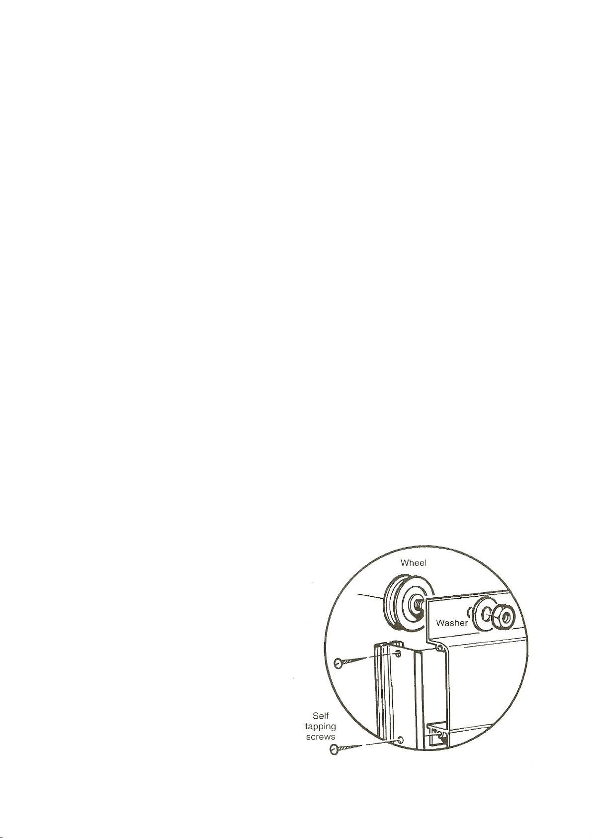
7. Fix each door wheel into position by pushing the bolt provided through the centre of the
wheel and then through the hole in the top door panel from underneath (i.e. from the inside of
the door). Put the washer over the bolt and secure with the nut provided, tightening until there
is no movement on the bolt. The nuts are lock-nuts and are harder to put on than normal nuts
in general assembly. The wheel will revolve freely because it has ball bearings in it. The
wheel has a collar protruding from the centre, this collar goes against the inside face of
the top door panel. (See picture below).
8. Slip the nylon door skids on each of the bottom panels. This may already have been done pri
or to delivery. After fitting the doors (see later in the booklet), you may need to lower the
door skid so that it engages with the bottom door cill to allow smooth movement of the door.
Lower the skid on each door and insert a self tapping screw at each end of the skid to rein
force the position.
9. Build the right hand door using the remaining handed and unhanded door post. Viewed from
the outside, the handed door post will be on the left of the door, while the unhanded door post
will be on the right. At this point you must decide the height you would like your door lock.
The hole to take the door lock is on the left hand side of the infill panel. You can decide to fit
this panel to the 2nd or 3rd panel down. Make sure you fit the glass before final fixing of
the door. See glazing plan towards the back of this booklet.
10. Thread the stainless steel backed brush extruder into the PVC carrier. This may already have
been done prior to delivery.
11. Turn the doors over and insert the black
brush draught excluder in the groove
(bolt slot) in the unhanded door posts.
Insert a nut and bolt at the bottom of
each unhanded door post and tighten so
that the brush will not slip down when
the door is in its upright position. Cut off
the surplus brush and carrier at the top of
the bar.
12. Do not fit the door to the gable at this
stage –wait until the structure is fully
assembled prior to glazing.
13. Door handles can now be fitted.

Other Elite Greenhouses Greenhouse Kit manuals

Elite Greenhouses iGrow User manual

Elite Greenhouses

Elite Greenhouses iGrow User manual

Elite Greenhouses 8'5" Wide Thyme User manual

Elite Greenhouses

Elite Greenhouses 8'5" Wide Thyme User manual

Elite Greenhouses 6'3" WIDE HIGH EAVE User manual

Elite Greenhouses

Elite Greenhouses 6'3" WIDE HIGH EAVE User manual

Elite Greenhouses 7'5'' VANTAGE User manual

Elite Greenhouses

Elite Greenhouses 7'5'' VANTAGE User manual

Elite Greenhouses TITAN 1000 User manual

Elite Greenhouses

Elite Greenhouses TITAN 1000 User manual

Elite Greenhouses 5' 3" WIDE DELTA User manual

Elite Greenhouses

Elite Greenhouses 5' 3" WIDE DELTA User manual

Elite Greenhouses TITAN K800 User manual

Elite Greenhouses

Elite Greenhouses TITAN K800 User manual

Elite Greenhouses 2'3'' Wide Easy Grow User manual

Elite Greenhouses

Elite Greenhouses 2'3'' Wide Easy Grow User manual

Elite Greenhouses 7'5" WIDE TITAN User manual

Elite Greenhouses

Elite Greenhouses 7'5" WIDE TITAN User manual

Elite Greenhouses 6'3" WIDE THYME User manual

Elite Greenhouses

Elite Greenhouses 6'3" WIDE THYME User manual

Elite Greenhouses 6'5" WIDE TITAN User manual

Elite Greenhouses

Elite Greenhouses 6'5" WIDE TITAN User manual

Elite Greenhouses STRATA User manual

Elite Greenhouses

Elite Greenhouses STRATA User manual

Elite Greenhouses WIDE MAXIM User manual

Elite Greenhouses

Elite Greenhouses WIDE MAXIM User manual

Elite Greenhouses 6'3" WIDE CRAFTSMAN User manual

Elite Greenhouses

Elite Greenhouses 6'3" WIDE CRAFTSMAN User manual

Elite Greenhouses TITAN 1200 User manual

Elite Greenhouses

Elite Greenhouses TITAN 1200 User manual

Elite Greenhouses STREAMLINE Series User manual

Elite Greenhouses

Elite Greenhouses STREAMLINE Series User manual

Popular Greenhouse Kit manuals by other brands

Vitavia VM0005-V Assembly instructions

Vitavia

Vitavia VM0005-V Assembly instructions

greenhouse sensation Quadgrow Assembly instructions

greenhouse sensation

greenhouse sensation Quadgrow Assembly instructions

Vitavia TARGET 6200 Assembly instructions

Vitavia

Vitavia TARGET 6200 Assembly instructions

Palram Glory 8'x8' Premium Class Greenhouse Assembly instructions

Palram

Palram Glory 8'x8' Premium Class Greenhouse Assembly instructions

Palram Hybrid 6'x14' manual

Palram

Palram Hybrid 6'x14' manual

Palram CANOPIA HARMONY 6x4/2x13 manual

Palram

Palram CANOPIA HARMONY 6x4/2x13 manual

Palram Grow&Store - 6'x12' Assembly instructions

Palram

Palram Grow&Store - 6'x12' Assembly instructions

Halls Atrium manual

Halls

Halls Atrium manual

Juliana Orangeri Assembly instructions

Juliana

Juliana Orangeri Assembly instructions

ClearSpan 500 Cold Frame Series manual

ClearSpan

ClearSpan 500 Cold Frame Series manual

Lacewing Lacewing GH1247 Assembly instructions

Lacewing

Lacewing Lacewing GH1247 Assembly instructions

GrowSpan Flip-Top Cold Frame Assembly manual

GrowSpan

GrowSpan Flip-Top Cold Frame Assembly manual

RUSTA 623011470101 manual

RUSTA

RUSTA 623011470101 manual

Strend Pro 2172588 installation instructions

Strend Pro

Strend Pro 2172588 installation instructions

Palram Americana 12'x12' Hybrid Glazing Assembly instructions

Palram

Palram Americana 12'x12' Hybrid Glazing Assembly instructions

Robinsons Reach REGAL Assembly instructions

Robinsons

Robinsons Reach REGAL Assembly instructions

Palram CANOPIA HARMONY 6x4 / 2x1.3 How to assemble

Palram

Palram CANOPIA HARMONY 6x4 / 2x1.3 How to assemble

ACD Blackline R206H manual

ACD

ACD Blackline R206H manual

manuals.online logo
manuals.online logoBrands
  • About & Mission
  • Contact us
  • Privacy Policy
  • Terms and Conditions

Copyright 2025 Manuals.Online. All Rights Reserved.