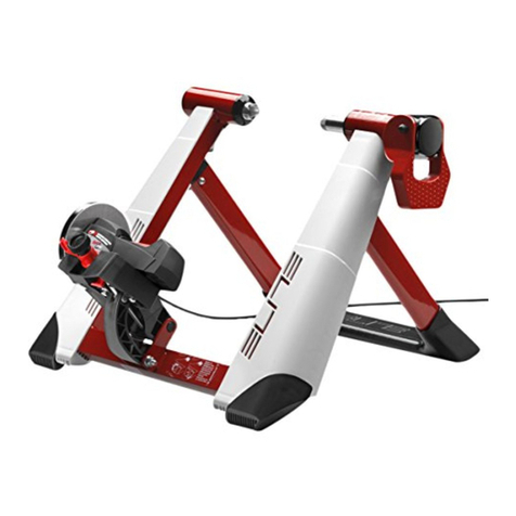
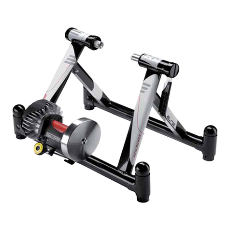
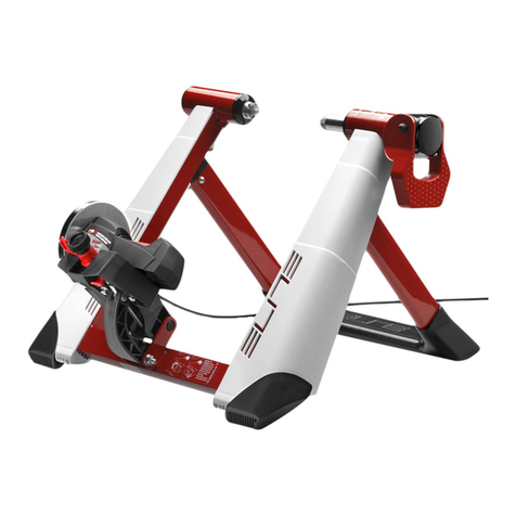
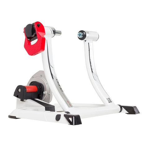
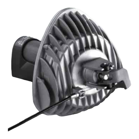
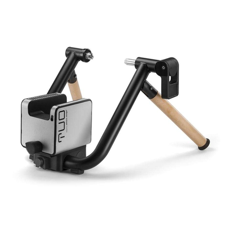
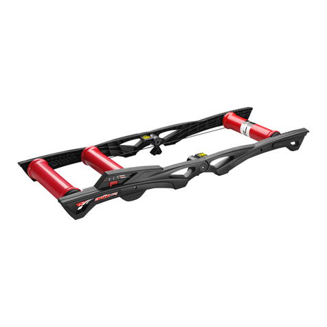
Elite Novo User manual

NOVO FRAME
ANLEITUNG
INSTRUCTIONS
INSTRUCCIONES
INSTRUCTIONS
ISTRUZIONI
説明書
INSTRUCTIES
INSTRUKCJE
INSTRUÇÕES
DE
EN
ES
FR
IT
JP
NL
PL
PT

DE
EN
FR
ES
IT
01_ALLGEMEINE SICHERHEITSHINWEISE 10
02_ÄNDERUNGEN AN DEN PRODUKTEN 10
03_EINLEITUNG 10
04_MONTAGE DES GESTELLS 10
05_MONTAGE DER EINHEIT 11
06_INSTALLIERUNG DES FAHRRADS 11
07_HERAUSNEHMEN VOM FAHRRAD 11
08_ACHTUNG! 11
09_HINWEISE ZUM GEBRAUCH 12
01_GENERAL SAFETY WARNINGS 13
02_PRODUCT MODIFICATIONS 13
03_INTRODUCTION 13
04_STAND ASSEMBLY 13
05_UNIT INSTALLATION 13
06_FITTING THE BICYCLE 14
07_BIKE REMOVAL 14
08_ATTENTION 14
09_ADVICE ON USE 14
01_ADVERTENCIAS GENERALES DE SEGURIDAD 15
02_MODIFICACIONES EN LOS PRODUCTOS 15
03_INTRODUCCIÓN 15
04_ENSAMBLAJE SOPORTE 15
05_MONTAJE UNIDAD 15
06_INSTALACIÓN DE LA BICICLETA 16
07_CÓMO SACAR LA BICICLETA 16
08_ATENCIÓN 16
09_CONSEJOS DE USO 16
01_AVERTISSEMENTS GENERAUX EN MATIERE
DE SECURITÉ 18
02_MODIFICATIONS APPORTÉES AUX PRODUITS 18
03_INTRODUCTION 18
04_ASSEMBLAGE DU SUPPORT 18
06_INSTALLATION DE LA BICYCLETTE 19
07_ENLÈVEMENT DE LA BICYCLETTE 19
08_ATTENTION 19
09_CONSEILS POUR L’UTILISATION 20
01_AVVERTENZE GENERALI DI SICUREZZA 21
02_MODIFICHE AI PRODOTTI 21
03_INTRODUZIONE 21
04_ASSEMBLAGGIO CAVALLETTO 21
05_MONTAGGIO UNITÁ 21
06_INSTALLAZIONE DELLA BICICLETTA 22
07_RIMOZIONE DELLA BICICLETTA 22
08_ATTENZIONI 22
09_CONSIGLI PER L'UTILIZZO 22

JP
NL
PT
PL
01_ADVERTÊNCIAS GERAIS DE SEGURANÇA 33
02_ALTERAÇÕES AOS PRODUTOS 33
03_INTRODUÇÃO 33
04_MONTAGEM DO CAVALETE 33
05_APARELHO DE MONTAGEM 33
06_INSTALAÇÃO DA BICICLETA 34
07_REMOÇÃO DA BICICLETTA 34
08_ATENÇÃO 34
09_CONSELHOS PARA USO 34
01_安全上の一般警告 24
02_製品に対する修正に関して 24
03_各部の名称とリスト 24
04_フレームの組み立て 24
05_負荷ユニットの取り付け 24
06_自転車の取り付け 25
07_自転車の取り外し 25
08_注意 25
09_アドバイス 26
01_ALGEMENE VEILIGHEIDSMEDEDELINGEN 27
02_WIJZIGINGEN AAN PRODUCTEN 27
03_INLEIDING 27
04_MONTEREN VAN DE STANDAARD 27
05_MONTAGE VAN DE EENHEID 27
06_INSTALLATIE VAN DE FIETS 28
07_VERWIJDEREN VAN DE FIETS 28
08_OPGELET 28
09_ADVIEZEN 29
01_WAŻNE INFORMACJE DOTYCZĄCE
BEZPIECZEŃSTWA 30
02_ZMIANY W PRODUKTACH 30
03_WPROWADZENIE 30
04_MONTAŻ STOJAKA 30
05_MONTAŻ URZĄDZENIA 30
06_INSTALACJA ROWERU 31
07_ZDEJMOWANIE ROWERU 31
08_UWAGA 31
09_ZALECENIA DOTYCZĄCE UŻYCIA 31

A
D
E
C
B
H
F
G
I
H
F
G
OPEN CLOSE
1 2

≥ 28”
C
! CLICK !
! CLICK !
3 4
H
F
G
5 6
7 8
9 10

I
I
parallel
11
13
15
12
14
16
L
L
M
N
L
L
M
N
17 18

L
L
M
N
L
L
M
N
L
L
M
N
L
L
M
N
M
19 20
23
21
24
25 26
L
L
M
N
22

I
==
27
3029
32
28
31
3433

35

10
DE
Wir danken Ihnen für den Kauf des Novo
01_ALLGEMEINE SICHERHEITSHINWEISE
Bitte lesen Sie aus Sicherheitsgründen und
zum Schutz Ihrer eigenen Gesundheit vor
der Benutzung des Rollentrainers folgende
Hinweise:
1. Dieses Gerät ist nicht für die Verwen-
dung durch Personen vorgesehen (Kinder
eingeschlossen), die verminderte körperli-
che, sensorielle oder geistige Fähigkeiten
haben oder nicht über ausreichende Er-
fahrung und Kenntnisse verfügen, außer
sie werden beaufsichtigt oder haben
entsprechende erhalten.
2. Kinder sollten beaufsichtigt werden, um
sicherzustellen, dass sie nicht mit dem
Gerät spielen.
3. Lassen Sie sich vor Beginn des Trainings
einer sorgfältigen sportärztlichen Untersu-
chung unterziehen, um ihren aktuellen Ge-
sundheitszustand auszumachen.
4. Wählen Sie eine Trainingsmodalität, die
Ihrem Gesundheitszustand und Ihrer indi-
viduellen Leistungsfähigkeit angemessen
ist.
5. Brechen Sie das Training umgehend
ab und konsultieren Sie Ihren Arzt, wenn
Sie während des Trainings unerwartete
Ermüdungserscheinungen oder Schmer-
zen verspüren.
Die vorausgehenden Hinweise haben al-
lgemeinen Charakter und sie umfassen
nicht alle Vorsichtsmaßnahmen, die für
eine korrekte und sichere Benutzung des
Rollentrainers beachtet werden müssen,
für die ausschließlich der Benutzer verant-
wortlich ist.
02_ÄNDERUNGEN AN DEN PRODUKTEN
ELITE behält sich auch zur Anpassung an den
technologischen Fortschritt das Recht vor, Änderungen an
den Produkten oder ihren Spezifikationen vorzunehmen,
ohne den Kunden vorab darüber zu informieren, für:
a) Änderungen, die sich nicht negativ auf die Leistungen
des Produkts auswirken;
b) Änderungen, die erforderlich sind, um die Spezifikationen
des Produkts zu erfüllen oder zu verbessern;
c) Änderungen, die zur Anpassung an anwendbare
gesetzliche Bestimmungen oder Regelungen erforderlich
sind.
ELITE behält sich außerdem das Recht vor, die Produkte
mit diesen Verbesserungen ohne jede Verpflichtung zu
liefern, die gleichen Änderungen an den zuvor erworbenen
Produkten vorzunehmen, und behält sich außerdem das
Recht vor, die Preise und die Verfügbarkeit der Modelle in
Abhängigkeit von den Marktbedingungen, die Verfügbarkeit
der Komponenten sowie weiteren Erwägungen des
Unternehmens zu ändern.
03_EINLEITUNG
Überprüfen Sie, dass alle nachstehenden Komponenten
vorhanden sind:
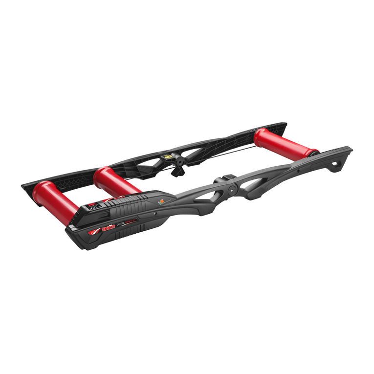
N°1 Rahmen Novo (Bez. A)
N°1 Widerstandseinheit (Bez. B)
N°1 Halterung Einheit (Bez. C)
N°1 Schnellspanner
(Bez. D)
N°2 Stöpsel für Radgrößen über 28” (Bez. E)
N°1 Schraube (Bez. F)
N°2 Unterlegscheibe
(Bez. G)
N°1 Mutter (Bez. H)
N°1 Befestigungshebel (Bez. I)
ACHTUNG
Die Einheit in der Beschreibung dient nur als Beispiel
04_MONTAGE DES GESTELLS
• Das Gestell öffnen und auf einer ebener Fläche
positionieren.
• Die im Gestell vorhandenen Schrauben (F+G+H)
entfernen (Abb. 1).
• Die Halterung der Einheit (C) nehmen, mit den Fingern die
beiden im oberen Teil der Halterung vorhandenen Knöpfe
zuammendrücken (Abb. 2) und die Halterung in die beiden
Löcher des Rahmens einführen (Abb. 3 und Abb. 4).
• Unter Benutzung der in Abb. 1 vorhandenen Schrauben
(F+G+H) die Halterung der Einheit (C) am entsprechenden
Rahmen montieren (Abb. 5). Das korrekte Anzugsmoment
anwenden; andernfalls behindert man die Drehung der
Halterung der Einheit.

11
DE
05_MONTAGE DER EINHEIT
• An der Basis der Halterung sind zwei Lochpaare
vorhanden; die verschiedenen Löcher werden je nach
Radgröße des Fahrrads benutzt:
1) für Räder ≥ 24” ÷ ≤ 26”, vorderes Lochpaar (Abb. 6);
2) für Räder ≥ 28”, hinteres Lochpaar (Abb. 7).
• Je nach Rad die Schrauben M6 vollständig befestigen
(Abb. 8 und Abb. 9).
• Bei Fahrrädern mit Radgröße über 28” muss ein Eingriff
am Rahmen vorgenommen werden, indem die Stöpsel der
vorderen Ständer gegen die in der Lieferung enthaltenen
größeren Stöpsel (E) ausgewechsel werden. Mit diesen
wird der Öffnungswinkel des Gestells verändert.
ACHTUNG: Dieser Vorgang muss bei von der
Halterung demontierter Einheit ausgeführt werden.
• Von beiden vorderen Ständern die Schrauben entfernen
(Abb. 10 und Abb. 11).
• Den Stöpsel entfernen, falls erforderlich unter
Zuhilfenahme eines Schraubenziehers (Abb. 12). Dieser
wird in den hierfür im Stöpsel vorgesehenen Sitz eingeführt
und nach unten gedrückt, was den Stöpsel durch
Hebelwirkung nach oben bewegt.
• Den gleichen Vorgang auch beim anderen Stöpsel
wiederholen.
• Die Stöpsel für Radgrößen über 28” (E) montieren, falls
erforderlich unter Zuhilfenahme eines Gummihammers
(Abb. 13).
• Die Rohre mit den dazugehörigen Schrauben wieder
positionieren (Abb. 10 und Abb. 11).
06_INSTALLIERUNG DES FAHRRADS
• Sicherstellen, dass der Schnellspanner des Hinterrads
korrekt befestigt ist.
• Den Hebel (I) in Position “open” stellen (Abb.14).
• Das Fahrrad bringen Sie in die richtige Position, indem
Sie das linke Ende des hinteren Schnellspanners in die linke
Buchse einführen (Abb. 15). Bitte prüfen Sie zur sicheren
Befestigung des Hinterrades, dass der Schnellspanner
parallel zum Boden steht. (Abb. 16).
• Den Hebel (I) schließen, wobei Sie darauf achten müssen,
dass der Hebel den Schnellspanner schon ab einem Winkel
von 55° - 65° umschließt (Abb. 17).
• Wenn der Hebel (I) beginnt, den Schnellspanner in der
vorgelegten Arbeitsposition zusammenzudrücken (Abb.
18), müssen Sie den Stift (L) der Recht Buchse anziehen
(Abb. 19), so dass der Hebel im Innern des vordefinierten
Arbeitsbereichs zu arbeiten beginnt (schon ab einem
Winkel von 55° - 65° umschließt) (Abb. 17).
• Wenn der Hebel (I) ) beginnt, den Schnellspanner in der
zurückgelegten Arbeitsposition 13 zusammenzudrücken
(Abb. 20), den Stift (L) der linken Buchse aufschrauben
(Abb. 21), so dass der Hebel im Innern des vordefinierten
Arbeitsbereichs zu arbeiten beginnt (schon ab einem
Winkel von 55° - 65° umschließt) (Abb. 17).
• Überprüfen, dass der Hebel des Extrahubs (M) sich in
Pos. “OPEN” befindet (Abb. 22)
• Den Drehgriff (N) gegen den Uhrzeigersinn drehen (Abb.
23), bis die Rolle der Widerstandseinheit (M) das Rad leicht
berührt (Abb. 24).
• Den Hebel des Extrahubs (M) um 180° nach rechts ins
Pos. “CLOSE” drehen (Abb. 25) und den Druck des Rads
auf die Halterung der Einheit überprüfen (Abb. 26).
• Falls das Rad sich gegenüber der Mitte der Rolle als zu
stark verlagert erweist (Abb. 27), die Widerstandseinheit
verschieben, wobei der Hebel des Extrahubs auf “OPEN”
gestellt wird (Abb. 23). Die Befestigungsschrauben der
Einheit lockern (Abb. 28), in der korrekteren Position
blockieren (Abb. 29) und den Hebel des Extrahubs (M) um
180° nach rechts in die Position “CLOSE” zurückstellen
(Abb. 25).
• Das Fahrrad zur Widerstandseinheit hin schieben, bis das
Hinterrad die Rolle der Einheit selbst
berührt (Abb. 29).
07_HERAUSNEHMEN VOM FAHRRAD
• Den Hebel des Extrahubs öffnen (Abb. 25).
• Das Fahrrad mit einer Hand halten und mit der anderen
den Hebel (I) öffnen, indem er auf Position “open” gestellt
wird (Abb. 30). Das Fahrrad herausnehmen.
• Zum Transport oder zur Platzersparnis wird bei
Nichtbenutzung des Rollentrainers empfohlen, das Gestell
zu schließen.
• Um Platz zu sparen, wird empfohlen, den Drehknopf (N)
gegen den Uhrzeigersinn zu drehen (Abb. 23), bis er auf die
max. zulässige Höhe gebracht wurde (Abb. 31).
• Wenn man noch mehr Platz sparen möchte, besteht die
Möglichkeit, die Einheit vom Gestell zu lösen (Abb. 32-
33), den Rahmen zu schließen und parallel zum Fußboden
abzusetzen (Abb. 34).
ACHTUNG: Um Quetschungen an den Händen zu vermeiden,
wird empfohlen, sie während des Schließvorgangs nicht
zwischen den Ständern zu positionieren.
08_ACHTUNG!
• Vermeiden Sie, dass sich Personen, Kinder oder Tiere
während des Gebrauchs dem Rollentrainer nähern
können, da die in Bewegung oder Rotation befindlichen
Komponenten des Rollentrainers und des Fahrrads im Fall
eines Kontakts Schäden bewirken können.
• Bei Gebrauch vom Radsimulator auf keinen Fall
bremsen, da sonst die Rolle und die Reifen stark beschädigt
werden können!

12
DE
• Das Gestell wurde zur Benutzung durch einen einzigen
Radsportler entwickelt.
• Vor jedem Training die Sicherheit und Stabilität des
Fahrrads überprüfen.
• Sollte der Schnellspanner mit den Buchsen des Gestells
nicht kompatibel sein, muss er gegen den in der Lieferung
enthaltenen ausgetauscht werden (O).
• Es befinden sich keine einzeln benutzbaren Komponenten
im Innern.
• Da die Stützfüße aus weichem, rutschfesten Gummi
sind, können Sie während des Gebrauchs Gummispuren
auf dem Fußboden hinterlassen.
09_HINWEISE ZUM GEBRAUCH
• Für einen geringeren Verschleiß des Reifens und
eine bessere Haftung an der Rolle empfehlen wir die
Verwendung von 23 mm breiten Reifen.
• Empfohlener Reifendruck des Hinterrads: 7 - 8 atü für
Rennreifen; 3,5 - 4 atü für MTB-Reifen. In speziellen Fällen
den vom Hersteller empfohlenen Druck einhalten.
• Für einen leiseren Betrieb, bessere Haftung des Reifens
an der Rolle und Verminderung der Vibrationen Slick-
Reifen benutzen (auch für Mountainbike).
• Den Reifen vor Gebrauch mit Alkohol oder Wasser
reinigen.
• Falls ein Rutschen des Rads auf der Rolle der Einheit
festgestellt wird, den Druck der Rolle auf das Rad wie folgt
erhöhen:
1) Den Hebel des Extrahubs bis in Position “OPEN” drehen
(Abb. 22).
2) Den Drehgriff gegen den Uhrzeigersinn drehen und
dadurch den Druck der Rolle auf den Reifen erhöhen (Abb.
23).
3) Den Hebel des Extrahubs bis in Position “CLOSE” drehen
(Abb. 25).
• Wenn trotzdem noch ein Rutschen des Rads auf der
Rolle festgestellt wird, muss die Krafteinwirkung auf das
Pedal progressiver erfolgen. Das Training mit rutschendem
Reifen kann die Rolle und den Reifen auf irreparable Weise
beschädigen.
• Wenn der Stift des mitgelieferten Schnellspanners mehr
als 3 mm aus der Befestigungsmutter herausragt, den
hervorstehenden Teil abschneiden (Abb. 35).

13
EN
Thank you for choosing the Novo
01_GENERAL SAFETY WARNINGS
Before using your trainer, carefully read
the warnings listed below for your health
and safety.
1. The appliance is not to be used by
persons (including children) with reduced
physical, sensory or mental capabilities,
or lack of experience and knowledge,
unless they have been given supervision or
instruction.
2. Children being supervised not to play
with the appliance.
3. Before beginning a training programme,
undergo a physical examination certifying
good health.
4. Choose a training level compatible with
your physical endurance and the status of
your health.
5. If you feel particularly fatigued or sore
while exercising, stop using the trainer
immediately and consult your doctor.
The above warnings are general and not
exhaustive of all the precautions that
should be taken for the proper and safe
use of the trainer; which is solely the
responsibility of the user.
02_PRODUCT MODIFICATIONS
Also in view of any technical update, ELITE reserves
the right to make changes to the products or their
specifications without being obliged to notify or inform the
Customer beforehand for:
a) changes that do not affect negatively the product
performance;
b) changes required to meet or improve the product
specifications;
c) changes necessary for the products to comply with the
applicable legal requirements.
ELITE also reserves the right to supply these products with
these improvements without being obliged to or responsible
for applying the same modifications to any previously
purchased products, reserving also the right to change
prices and model availability according to market
conditions, component availability and other corporate
considerations.
03_INTRODUCTION
Check the presence of all the following components:
N°1 Novo frame (Ref. A)
N°1 Unit (Ref. B)
N°1 Unit support (Ref. C)
N°1 Quick release (Ref. D)
N°2 Plugs for wheels larger than 28” (Ref. E)
N°1 Screw (Ref. F)
N°2 Washer (Ref G)
N°1 Nut (Ref H)
N°1 Fixing lever (Ref I)
ATTENTION
Resistance unit depicted here may vary from production
models
04_STAND ASSEMBLY
• Open the stand and position it on aflat surface.
• Remove the screws (F+G+H) on the stand (Fig.1).
• Take the unit support (C), press the two buttons on the
upper part of the support (Fig. 2) with fingers, and fit it
inside the two holes in the frame (Fig.3 and Fig.4)
• Using the screw shown in Fig.1 (F+G+H), fit the unit
support (C) on the respective frame (Fig.5). Use the
correct tightening force, otherwise the unit support will be
prevented from turning.
05_UNIT INSTALLATION
• There are two pairs of holes in the base of the support;
use the various holes according to the bicycle wheel:
1) for wheels ≥ 24” ÷ ≤ 26”, front pair of holes (Fig. 6);
2) for wheels ≥ 28”, rear pair of holes (Fig.7).
• Depending on the wheel, tighten the M6 screws (Fig. 8
and Fig. 9).
• For bicycles with wheels larger than 28” it is necessary
to operates on the frame, changing the plugs of the front
uprights with the oversize plugs provided (E). These differ
for the stand opening angle.
ATTENTION: This operation must be carried out with the
unit removed from the support.
• Remove the screws from both front uprights (Fig.10 and
Fig.11).
• Remove the plug, using a screwdriver if necessary Fig.
12.
• Insert it inside the seat specially created in the plug and
prise, pushing the screwdriver downward and the plug

14
EN
upward.
• Repeat the same operation also for the other plug.
• Fit the plugs for wheels larger than 28” (E), using a
rubber hammer if necessary (Fig. 13).
• Reposition the tubes with respective screws (Fig. 10 and
Fig. 11).
06_FITTING THE BICYCLE
• Make sure the quick release of the bicycle rear wheel is
properly fixed.
• Turn the lever (F) to the “open” position (fig. 14).
• Put the bicycle in position, inserting the left end of the
rear quick release in the left bushing (fig. 15). For safer
clamping of the bicycle on the stand, make sure the lever
of the quick release is horizontal (fig. 16).
• Close the lever (I), making sure it starts pressing the
quick release inside the predefined work area; between
55° and 65° (Fig.17).
• If the lever (I) starts pressing the quick release in the
advanced work position (fig. 18), screw the right bushing
pin (L) (fig. 19) so that the lever starts working inside the
predefined work area (between 55° and 65°) (Fig.17).
• If the lever (I) starts pressing the quick release in the
delayed work position (fig. 20), unscrew the right bushing
pin (fig. 21) so that the lever starts working inside the
predefined work area (between 55° and 65°) (Fig.17).
• Make sure the overtravel lever (M) is in the “OPEN”
position (Fig. 22).
• Turn the knob (N) anticlockwise (Fig. 23) until the roller of
the resistance unit (M) touches the wheel (Fig. 24).
• Turn the overtravel lever (M) 180° to the right (Fig. 25) to
the “CLOSE” position and check the pressure of the wheel
on the unit support (Fig.26).
• If the wheel is moved too far from the middle of the Roller
(Fig.27), shift the resistance unit by bringing the overtravel
lever to the “OPEN” position (Fig.23), loosening the fixing
screws of the unit (Fig.28), tightening them in a more
correct position (Fig.29) and turning the overtravel lever (M)
180° to the right to the “CLOSE” position (Fig.25).
• Push the bicycle towards the resistance unit until the rear
wheel touches the roller (fig. 29).
07_BIKE REMOVAL
• Open the overtravel lever (Fig.25).
• Hold the bicycle with one hand and with the other open
the lever (I), turning it to the “open” position (fig. 30).
Remove the bicycle.
• For carrying, or storage, it is advisable to close the stand.
• For storage and transport, turn the knob (N) anticlockwise
(Fig. 23) up to its maximum height (Fig. 31).
• You can further reduce the space occupied by the trainer
by releasing the resistance unit from the frame (Fig. 32-33)
and folding it flat (Fig. 34).
ATTENTION: to avoid pinching of hands, do not to put them
between the uprights during the closing operation.
08_ATTENTION
• Keep people, children and animals away from the roller
during use, since the moving and rotating parts of the roller
and the bicycle can cause damage in case of contact.
• Before starting training, position the trainer in a dry place,
away from potentially hazardous objects (furniture, tables,
chairs, etc.) in order to avoid any risk of inadvertent or
accidental contact with them.
• The stand is designed for use by just one cyclist.
• Check the safety and stability of the bicycle before every
training session.
• If the quick release is not compatible with the bushings of
the stand, replace it with the one supplied (O).
• There are no individually usable components on the
inside.
• Since the feet are made from soft non-slip material,
during use they may leave rubber marks on the floor.
09_ADVICE ON USE
• For less tyre wear and better grip on the roller, it is
advisable to use tyres of 23 mm width.
• Recommended rear wheel pressure: 7 -8
atmospheres for racing tyres; 3.5 - 4 atmospheres for
MTB tyres. For particular cases, comply with the pressure
recommended by the tyre manufacturer.
• For quieter use, better grip of the tyre on the roller and
reduced vibration, use slick tyres (also for Mountain bikes).
• Before use, clean the tyre with alcohol or water.
• If any slipping of the wheel on the roller of the unit is
noticed, increase the pressure of the roller on the wheel
as follows:
1) Turn the overtravel lever to the “OPEN” position (Fig.22)
2) Turn the knob anticlockwise, thereby increasing the
pressure of the roller on the tyre (Fig.23)
3) Turn the overtravel lever to the “CLOSE” position (Fig.25)
• If, in any case, slipping of the wheel on the roller of the unit
is noticed, make the force on the pedal more progressive.
Training with the tyre slipping can permanently damage the
roller and tyre.
• If the pin of the quick release supplied protrudes more
than 3 mm from the fixing nut, cut off the protruding part
(fig. 35).

15
ES
Le agradecemos que haya escogido Novo
01_ADVERTENCIAS GENERALES DE
SEGURIDAD
Antes de empezar a usar el Drivo II, lea
atentamente las advertencias indicadas a
continuación para su salud y seguridad.
1. El aparato no debe ser utilizado por
personas (incluidos niños) con capacidades
físicas, sensoriales o mentales reducidas, o
sin experiencia o conocimientos, a menos
que sean adecuadamente supervisados y
formados.
2. Debe vigilarse que los niños no jueguen
con el aparato.
3. Antes de comenzar el entrenamiento,
sométase a un examen médico deportivo
de fondo que certifique su estado de buena
salud.
4. Elija un modo de entrenamiento que sea
compatible con sus condiciones de salud y
resistencia física.
5. Si durante el ejercicio experimenta
sensaciones de especial fatiga o dolor,
interrumpa inmediatamente el uso del
rodillo y consulte a su médico.
Las advertencias mencionadas
anteriormente son de carácter general y
no comprenden todas las precauciones
que deben tomarse para un uso correcto y
seguro del Drivo II , del cual el usuario es el
único responsable.
02_MODIFICACIONES EN LOS PRODUCTOS
ELITE, también en consonancia con la actualización
tecnológica, se reserva el derecho de realizar modificaciones
en los productos o sus características sin estar obligada a
notificarlas o a otra comunicación previa al cliente en caso
de:
a) modificaciones que no afecten de forma negativa el
rendimiento del producto;
b) modificaciones necesarias para cumplir o mejorar las
especificaciones del producto;
c) modificaciones necesarias para cumplir los requisitos
legales o reglamentarios aplicables.
ELITE también se reserva el derecho de suministrar productos
con tales mejoras sin ninguna obligación o responsabilidad
de introducir las mismas modificaciones en los productos
comprados previamente, y se reserva el derecho de cambiar
los precios y la disponibilidad de los modelos de acuerdo
con las condiciones del mercado, la disponibilidad de los
componentes y otras consideraciones de la empresa.
03_INTRODUCCIÓN
Verificar la presencia de todos los componentes
siguientes:
N°1 Bastidor Novo (Ref. A)
N°1 Unità (Ref. B)
N°1 Soporte unidad (Ref. C)
N°1 Sgancio Rapido (Ref. D)
N°2 Tapones para ruedas mayores de 28” (Ref. E)
N°1 Vite (Ref. F)
N°2 Rosette (Ref. G)
N°1 Dado (Ref. H)
N°1 Palanca de sujeción (Ref. I)
¡ATENCIÓN!
La unidad indicada en la figura de conjunto es
simplemente indicativa
04_ENSAMBLAJE SOPORTE
• Abrir el soporte y posicionarlo sobre una superficie plana.
• Quitar los tornillos (F+G+H) presentes en el caballete
(Fig.1);
• Coger el soporte unidad (C) apretar con los dedos los dos
botones presentes en la parte superior del soporte (Fig. 2) e
introducirlo dentro de los dos agujeros del bastidor (Fig.3 y
Fig.4).
• Usando los tornillos presentes en Fig.1 (F+G+H), montar
el soporte unidad (C) en el relativo bastidor (Fig.5). Usar la
correcta fuerza de apretamiento, de lo contrario se impedirá
al soporte unidad el poder girar.
05_MONTAJE UNIDAD
• En la base del soporte hay dos pares de agujeros, utilizar
los diferentes agujeros en base a la rueda de la bicicleta:
1)para ruedas ≥ 24” ÷ ≤ 26”, par de agujeros anteriores
(Fig.6);
2)para ruedas ≥ 28”, par de agujeros posteriores (Fig.7);
• Según la rueda, ir a fijar completamente los tornillos M6
(Fig.8 y Fig.9).
• Para bicicletas con ruedas mayores de 28” hay que
intervenir sobre el bastidor cambiando los tapones de los

16
ES
montantes anteriores por los tapones aumentados en
dotación (E) . Estos difieren por el ángulo de apertura del
caballete.
ATENCIÓN: esta operación se tiene que efectuar cuando la
unidad ha sido desmontada del soporte.
• Quitar los tornillos de ambos montantes anteriores (Fig.10
y Fig.11).
• Quitar el tapón ayudándose si necesario con un
destornillador Fig.12. Introducirlo en el interior del
alojamiento creado especialmente en el tapón y hacer
palanca empujando el destornillador hacia abajo y el tapón
hacia arriba.
• Repetir la misma operación también con el otro tapón.
• Montar los tapones para ruedas mayores de 28” (E),
ayudándose si necesario con un martillo de goma (Fig.13).
• Volver a posicionar los tubos, con sus tornillos (Fig.10 y
Fig.11).
06_INSTALACIÓN DE LA BICICLETA
• Comprobar que el blocaje rápido de la rueda
posterior de la bicicleta esté fijado correctamente.
• Posicionar la palanca (I) en posición “open” (fig. 14).
• Colocar en posición la bicicleta, introduciendo el extremo
de izquierda del blocaje rápido posterior en el casquillo
izquierdo (fig. 15). Para un bloqueo más seguro de la
bicicleta sobre el soporte, comprobar que la palanca del
blocaje rápido esté colocada en sentido horizontal (fig. 16).
• Cerrar la palanca (I), ponendo atención que empiece a
comprimir el blocaje rápido en el interior del área de trabajo
predeterminada, la delimitada desde 55° hasta 65° (Fig.17).
• Si la palanca (I) empieza a comprimir el blocaje rápido en
la posición de trabajo anticipada (fig.18), atornillar el perno
casquillo derecho (L) (fig.19) de tal manera que la palanca
empiece a trabajar en el interior del área de predeterminada
(la delimitada desde 55° hasta 65°) (Fig.17).
• Si la palanca (I) empieza a comprimir el blocaje rápido en la
posición de trabajo postergada (fig.20), destornillar el perno
casquillo izquierdo (L) (fig. 21) de tal manera que la palanca
empiece a trabajar 13 en el interior del área predeterminada
(la delimitada desde 55° hasta 65°) (Fig.17).
• Verificar que la palanca de la extracarrera (M)
esté posicionada en “OPEN” (Fig. 22).
• Girar la manopla (N) en sentido antihorario (Fig.23) hasta
que el rodillo de la unidad de resistencia (M) roce la rueda
(Fig.24).
• Girar la palanca de la extracarrera (M) de 180° hacia la
derecha (Fig.25), en la posición de “CLOSE” y verificar la
compresión de la rueda sobre el soporte unidad (Fig.26).
• Si la rueda resultara demasiado desplazada con respecto
al centro del Rodillo (Fig.27), hay que mover la unidad de
resistencia volviendo a llevar la palanca de la extracarrera
en “OPEN” (Fig.23), aflojando los tornillos de sujeción de
la unidad (Fig.28), bloquearlos en la posición más correcta
(Fig.29) y devolviendo la palanca de la extracarrera (M) hacia
la derecha de 180°, en la posición de “CLOSE” (Fig.25).
• Empujar la bicicleta hacia la unidad de resistencia, hasta
que la rueda posterior entre en contacto con el rodillo de la
unidad misma (fig. 29).
07_CÓMO SACAR LA BICICLETA
• Abrir la palanca de la extracarrera (Fig.25).
• Agarrar la bicicleta con una mano y con la otra abrir la
palanca (I) llevándola a la posición “open” (fig. 30). Retirar
la bici.
• Para el transporte o para reducir el espacio ocupado
cuando no se utiliza el rodillo, aconsejamos cerrar el soporte.
• Si se quiere ocupar menos espacio con el rodillo,
aconsejamos girar el mando (N) en sentido anti-horario (Fig.
23), hasta llevarlo a la altura máxima permitida (Fig. 31).
• Si se quiere minimizar posteriormente el espacio ocupado,
es posible desenganchar la unidad del caballete (Fig. 32-
33), cerrar el bastidor y apoyarlo paralelamente al suelo (Fig.
34).
ATENCIÓN: para evitar pellizcarse las manos, aconsejamos
no colocarlas entre los montantes durante la operación de
cierre.
08_ATENCIÓN
• Evita que personas, niños o animales se acerquen al rodillo
durante su uso puesto que los componentes en movimiento
o giratorios del rodillo y de la bicicleta pueden provocar
daños en caso de contacto.
• Antes de empezar el entrenamiento, posicionar el rodillo
en un lugar adecuado, lejos de objetos potencialmente
peligrosos (muebles, mesas, sillas...) para así evitar todo
riesgo de contacto involuntario y accidental con los mismos.
• El soporte ha sido estudiado para que lo utilice un solo
ciclista.
• Verificar la seguridad y la estabilidad de la bicicleta antes
de cada entrenamiento.
• En caso el blocaje rápido no fuese compatible con los
casquillos del soporte, sustituirlo con el entregado en
dotación (O).
• No hay, en el interior, componentes utilizables
individualmente.
• Puesto que los pies de apoyo están fabricados con material
blando anti-deslizamiento, podría ocurrir que durante el uso
dejaran marcas de goma sobre el pavimento.
09_CONSEJOS DE USO
• Para un menor desgaste del neumático y una mayor
adherencia al rodillo, aconsejamos utilizar neumáticos
anchos 23 mm.

17
ES
• Presión aconsejada de la rueda posterior: 7 - 8 atmósferas
para neumático de carretera, 3,5 - 4 atmósferas para
neumático MTB. Para casos particulares atenerse a la
presión aconsejada por el fabricante de los neumáticos.
• Para un menor ruido, una mayor adherencia del neumático
sobre el rodillo y una reducción de las vibraciones, utilizar
neumáticos slick (también para Mountain bike).
• Antes del uso, limpiar el neumático con alcohol o agua.
• Si se nota que la rueda patina sobre el rodillo de la unidad,
hay que aumentar la compresión del rodillo sobre la rueda
de la manera siguiente:
1)Girar la palanca de la extracarrera hasta la posición
“OPEN” (Fig.22)
2)Girar en sentido antihorario la manopla aumentando de
esta manera la compresión del rodillo sobre el neumático
(Fig.23)
3)Girar la palanca de la extracarrera hasta la posición
“CLOSE” (Fig.25)
• Si de todos modos se notara que la rueda sigue patinando
sobre el rodillo de la unidad, hacer más progresivo el
esfuerzo sobre el pedal. El entrenamiento con el neumático
que patina puede dañar irremediablemente el rodillo y el
neumático.
• Si el perno del blocaje rápido entregado sobresale más de
3 mm de la tuerca de fijación, cortar la parte que sobresale
(fig. 35).

18
FR
Merci d’avoir acheté Novo
01_AVERTISSEMENTS GENERAUX EN
MATIERE DE SECURITÉ
Avant toute utilisation du rouleau d’en-
traînement et pour votre santé et votre
sécurité, veuillez lire avec attention les mi-
ses en garde indiquées ci-après.
1. L’appareil ne doit pas être utilisé par
des personnes (y compris les enfants)
ayant des capacités physiques, sensoriel-
les ou mentales réduites ou un manque
d’expérience et de connaissance, à moins
qu’elles n’aient été informées ou rensei-
gnées de façon appropriée.
2. Veuillez surveiller vos enfants et leur in-
terdire de jouer avec l’appareil.
3. Avant de commencer l’entraînement,
veuillez passer une visite médico-sportive
complète qui certifiera que vous êtes en
bonne santé.
4. Choisissez un mode d’entraînement qui
soit compatible avec votre condition et ca-
pacité de résistance physique.
5. Si, lors de l’entraînement, vous ressen-
tez une sensation de grande fatigue ou des
douleurs particulières, veuillez immédiate-
ment interrompre l’utilisation du rouleau et
vous rendre chez votre médecin traitant.
Les avertissements susmentionnés ont
un caractère général et non exhaustif de
l’ensemble des précautions qui doivent
être adoptées pour une utilisation correcte
et appropriée du rouleau d’entraînement,
dont l’utilisateur est exclusivement respon-
sable.
02_MODIFICATIONS APPORTÉES AUX
PRODUITS
ELITE, en fonction également de ses adaptations aux nouvelles
technologies, se réserve le droit d’apporter des modifications
aux produits ainsi qu’à leurs spécifications sans obligation
de notification ou de toute autre communication préalable à
destination du Client au sujet de :
a) modifications n’ayant pas un impact négatif sur les
prestations du produit ;
b) modifications nécessaires à la satisfaction ou à
l’amélioration des caractéristiques du produit ;
c) modifications relatives à l’adaptation aux exigences prévues
par la loi ou les règlements applicables.
De plus, ELITE se réserve le droit de proposer ses produits
dotés desdites améliorations sans aucune obligation ou
responsabilité d’apporter les mêmes modifications aux
produits précédemment achetés, et se réserve aussi le droit
de modifier les prix et la disponibilité des modèles selon les
conditions du marché, la disponibilité des composants et tout
autre aspect pris en considération par l’entreprise.
03_INTRODUCTION
Vérifiez la présence de toutes les pièces suivantes:
N°1 Châssis Novo (Réf. A)
N°1 Unité (Réf. B)
N°1 Support unité (Réf. C)
N°1 Déclenchement instantané (Réf. D)
N°2 Bouchons pour roues supérieures à 28” (Réf. E)
N°1 Vis (Réf. F)
N°2 Rondelle (Réf. G)
N°1 Écrou (Réf. H)
N°1 Levier de Fixage (Réf. I)
ATTENTION
L’unité indiquée sur le dessin d’ensemble est purement
indicative
04_ASSEMBLAGE DU SUPPORT
• Ouvrez le support et positionnez-le sur une
surface plate.
• Enlevez la visserie (F+G+H) présente sur le support (Fig.1).
• Prenez le support unité (C) appuyez avec les doigts sur les
deux boutons présents sur la partie supérieure du support (Fig.
2) et insérez-le à l’intérieur des deux trous du châssis (Fig.3 et
Fig.4).
• En utilisant la visserie présente sur la Fig.1 (F+G+H),
assemblez le support unité (C) au châssis correspondant
(Fig.5). Utilisez la bonne force de serrage, autrement cela
empêchera au support unité de tourner.

19
FR
05_ASSEMBLAGE UNITÉ
• Sur la base du support il y a deux paires de trous, utilisez les
différents trous selon la roue du vélo:
1)pour des roues ≥ 24” ÷ ≤ 26”, paire de trous antérieurs
(Fig.6);
2)pour des roues ≥ 28”, paires de trous postérieurs (Fig.7).
• Selon la roue fixez complètement les vis M6 (Fig.8 et Fig.9).
• Pour des vélos avec des roues supérieures à 28” il faudra
intervenir sur le châssis en changeant les bouchons des
montants antérieurs avec les bouchons plus grands fournis (E)
. Ils sont différents de par l’angle d’ouverture du support.
ATTENTION: cette opération doit être effectuée quand l’unité
n’est pas assemblée au support.
• Enlevez la visserie des deux montants antérieurs (Fig.10 et
Fig.11).
• Enlevez le bouchon en vous aidant au besoin avec un
tournevis Fig.12.
• Insérez-le à l’intérieur du logement créé expressément dans
le bouchon et faites levier en poussant le tournevis vers le bas
et le bouchon vers le haut.
• Répétez la même opération pour l’autre bouchon aussi.
• Montez les bouchons pour roues supérieures à 28” (E),
en vous aidant au besoin avec un marteau en caoutchouc
(Fig.13).
• Repositionnez les tubes avec la visserie jointe (Fig.10 et
Fig.11).
06_INSTALLATION DE LA BICYCLETTE
• Assurez-vous que le déclenchement instantané de la roue
postérieure de la bicyclette soit fixé correctement.
• Positionnez le levier (F) en position “open” (fig. 14).
• Mettez la bicyclette en position en insérant l’extrémité
gauche du déclenchement instantané postérieur dans le
fourreau gauche (fig. 15). Pour un blocage plus sûr de
la bicyclette sur le support, assurez-vous que le levier du
déclenchement instantané soit tourné à l’horizontale (fig. 16).
• Fermez le levier (I), en veillant à ce qu’il commenceà
comprimer le déclenchement instantané à l’intérieur de la
zone de travail prédéfinie, celle qui est délimitée de 55° à 65°
(Fig.17).
• Si le levier (I) commence à comprimer le déclenchement
instantané dans la position de travail anticipée (fig. 18), vissez
l’axe douille droit (L) (fig. 19) de manière à ce que le levier
commence à travailler à l’intérieur de la zone prédéfinie (celle
qui est délimitée de 55° à 65°) (Fig.17).
• Si le levier (I) commence à comprimer le déclenchement
instantané dans la position de travail posticipée (fig. 20),
dévissez l’axe douille gauche (L) (fig.21) de manière à ce que
le levier commence à travailler à l’intérieur de la zone de travail
prédéfinie (celle qui est délimitée de 55° à 65°) (Fig.17).
• Vérifiez que le levier de l’extracourse (M) soit positionné sur
“OPEN” (Fig.22).
• Tournez le bouton (N) en sens antihoraire (Fig.23) jusqu’à
ce que le galet de l’unité de résistance (M) effleure la roue
(Fig.24).
• Tournez le levier de l’extracourse (M) de 180° vers la droite
(Fig.25), sur la position de “CLOSE” et vérifiez la compression
de la roue sur le support unité (Fig.26).
• Dans le cas où la roue serait trop déplacée par rapport
au centre du Galet (Fig.27), déplacez l’unité de résistance
en remettant le levier de l’extracourse sur “OPEN” (Fig.23),
en desserrant les vis de fixage de l’unité (Fig.28), bloquez-
les sur la meilleure position (Fig.29) et remettez le levier de
l’extracourse (M) à 180° vers la droite, sur la position de
“CLOSE” (Fig.25).
• Poussez la bicyclette vers l’unité de résistance,
jusqu’à ce que la roue postérieure entre en contact avec le
rouleau de l’unité (fig. 29).
07_ENLÈVEMENT DE LA BICYCLETTE
• Ouvrez le levier de l’extracourse (Fig.25).
• Tenez la bicyclette d’une main et de l’autre ouvrez le levier
(I) en le mettant en position “open” (fig. 30). Enlevez le vélo.
• Pour le transport ou pour réduire l’encombrement quand on
utilise pas le rouleau, nous conseillons de fermer le support en
tournant la base de l’unité.
• Si l’on souhaite réduire l’espace occupée par le rouleau,
nous conseillons de tourner le bouton (N) dans le sens inverse
des aiguilles d’une montre (Fig. 23), jusqu’à l’amener à la
hauteur maximum admise (Fig. 31).
• Si l’on veut minimiser ultérieurement l’encombrement on
peut décrocher l’unité du support (Fig.32-33), refermer le
châssis et le poser parallèlement au sol (Fig. 34).
ATTENTION: pour éviter de vous pincer les doigts nous vous
conseillons de ne pas les mettre entre les montants pendant
l’opération de fermeture.
08_ATTENTION
• Evitez que des personnes, des enfants ou animaux puissent
s’approcher du rouleau pendant l’utilisation parce que des
éléments en mouvement ou tournants du rouleau et du vélo
peuvent provoquer des dommages en cas de contact.
• Avant de commencer l’entrainement, positionnez le trainer à
un endroit adapté, loin d’objets qui pourraient être dangereux
(meubles, tables, chaises…) de manière à éviter tout risque
de contact involontaire et accidentel avec ces objets.
• Le support est étudié pour l’utilisation de la part d’un seul
cycliste.
• Vérifiez la sécurité et la stabilité de la bicyclette avant tout
entrainement.
• Dans le cas où le déclenchement instantané ne serait pas
compatible avec les douilles du support, remplacez-le avec

20
FR
celui qui est fourni (O).
• Il n’y a pas de pièces utilisables individuellement à l’intérieur.
• Vu que les pieds sont construits en matière souple adhérente,
il se pourrait qu’ils laissent des traces de caoutchouc sur le sol
pendant l’entrainement.
09_CONSEILS POUR L’UTILISATION
• Pour moins user le pneu et pour avoir une meilleure
adhérence au rouleau, nous conseillons d’utiliser des pneus
de 23 mm de largeur.
• Pression conseillée pour la roue postérieure: 7 -8 bars pour
pneu de course; 3,5 - 4 bars pour pneu VTT. Pour les cas
particuliers respectez la pression conseillée par le constructeur
du pneu.
• Pour avoir moins de bruit, plus d’adhérence du pneu au
rouleau et une réduction des vibrations, utilisez des pneus
slick (même pour VTT).
• Avant l’utilisation, nettoyez le pneu avec de l’alcool ou de
l’eau.
• Dans le cas où l’on sentirait un glissement de la roue sur le
galet de l’unité il faut augmenter la compression du galet sur
la roue de la façon suivante:
1)Tournez le levier de l’extracourse jusqu’à la position “OPEN”
(Fig.22)
2)Tournez en sens antihoraire le bouton et augmentez ainsi la
compression du galet sur le pneu (Fig.23)
3) Tournez le levier de l’extracourse jusqu’à la position
“CLOSE” (Fig.25)
• Si l’on sent de toute façon un glissement de la roue sur
le galet de l’unité il faut rendre plus progressif l’effort sur
la pédale. L’entrainement avec un pneu qui glisse peut
endommager irrémédiablement le galet et le pneu.
• Si l’axe du déclenchement instantané fourni dépasse de plus
de 3 mm de l’écrou de fixage, coupez la partie qui dépasse
(fig. 35).
Other manuals for Novo
2
Table of contents
Languages:
Other Elite Fitness Equipment manuals

Elite
Elite E-Motion User manual

Elite
Elite Mag User manual

Elite
Elite DRIVO II User manual

Elite
Elite SUITO User manual

Elite
Elite TURBO MUIN SMART B+ User manual

Elite
Elite DRIVO User manual

Elite
Elite QUBO User manual

Elite
Elite Crono Power Fluid User manual

Elite
Elite QUBO User manual

Elite
Elite REALPOWER wireles ANT User manual