manuals.online logo
Brands
  1. Home
  2. •
  3. Brands
  4. •
  5. Elko
  6. •
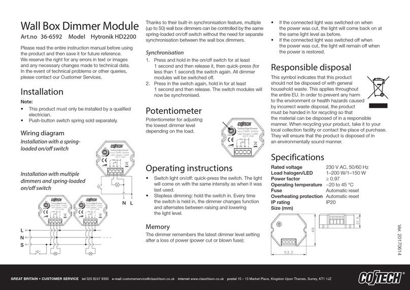
  7. Dimmer
  8. •
  9. Elko DIM-2 User manual

Elko DIM-2 User manual

1 / 2
DIM-2
02-190/2016 Rev.: 0
3
1
2
45
6
7
8
9
10 11
A2
A1
V
T1
T2
h
T2
A1 V
A2 T1
N
L
T 2.5 A
R, L
abcde f
R
LC
xx xx xxx
zz ---
z-
230V AC
ELKO EP, s.r.o.
Palackého 493
769 01 Holešov, Všetuly
Czech Republic
Tel.: +420 573 514 211
e-mail: [email protected]
www.elkoep.com
Staircase switch with dimming
Characteristics
Description
Symbol
Connection
EN
• designated for dimming el. bulbs, halogen lights and halogen lights with winding
transformers
• intelligent control of halogen lights, function of gradual switching on and dim-
ming
• controlling inputs for push button and switch
• values are set by potentiometers on front panel of the product, adjustable:
- maximum dim-up
- speed (uency) of dim-up
- speed (uency) of dim-down
- time for which a light is on with maximum dim-up
• all time intervals can be adapted according to a request
• output without contact: 1x triac
• load AC 5b (el. bulbs) 500 W
• clamp terminals
• parallel connection of controlling pushbuttons is possible
• protection against over-temperature inside the product - switches output o +
signalizes overheating by LED ashing
• 1-MODULE, DIN rail mounting
• Note: possibility of start and nish adjustment up on 1 hour, device has descrip-
tion DIM-2-1h
1. Output
2. Supply voltage terminal
3. Control input for push button - is a
service switch (possibility to switch a
light on permanently)
4. Output indication - red LED:
- start - LED ashes in medium pace
- delay - LED is on
- end - LED slowly ashes
- temperature overload - output dis-
connected, LED ashes quickly
5. Supply voltage indication
6. - brightness setting: 10 - 100%
7. t1 - dim-up time setting: 1 - 40 s
8. t3 - dim-down time setting: 1 - 40 s
9. t2 - time dwell setting: 0 s - 20 min
10. Supply terminals
11. Controlling input for switch - to
control dimmers (for example in
staircases). This input is protected
against undesired button blocking (for
example by a match). Length of button
pressing doesn´t inuence length of
cycle.
T 2.5 A - ballast protection recommended
When load is above 300 VA it is necessary to ensure sucient cooling.
Recommendation for mounting: leave a gap of min. 0.5 module (approx. 9 mm) on side
of the device to ensure better cooling of the device.
a) lamp,halogen light
b) low-voltage el.bulbs 12/24V wound transformers
c) low-voltage el.bulbs 12/24V electronic transformers
d) LED bulbs
e) saving uorescent lamps
f) switching management
x - dimmable
xx - incline edge
xxx - descending edge
Product loadability
2 / 2
DIM-2
T1
t1 t3
t2
T2
t1 t3
t2
Warning
Technical parameters Function
- brightness
T1, T2 - controlling input
t1 - dim-up time
Controlled via input T1 (button)
Dim-up delay-down is started by a button.
Cycle extension - by re-pressing button
(during the cycle).
t2 - time delay
t3 - dim-down time
Controlled via input T2 (switch)
The switch starts the cycle and it stops on
max.set brightness. After the switch is o,
the cycle will continue until completed.
Device is constructed for connection in 1-phase main AC and must be installed according to
norms valid in the state of application. Connection according to the details in this direction. In-
stallation, connection, setting and servicing should be installed by qualied electrician sta only,
who has learnt these instruction and functions of the device. This device contains protection
against overvoltage peaks and disturbancies in supply. For correct function of the protection of
this device there must be suitable protections of higher degree (A, B, C) installed in front of them.
According to standards elimination of disturbancies must be ensured. Before installation the
main switch must be in position “OFF” and the device should be de-energized. Don´t install the
device to sources of excessive electro-magnetic interference. By correct installation ensure ideal
air circulation so in case of permanent operation and higher ambient temperature the maximal
operating temperature of the device is not exceeded. For installation and setting use screw-driv-
er cca 2 mm. The device is fully-electronic - installation should be carried out according to this
fact. Non-problematic function depends also on the way of transportation, storing and handling.
In case of any signs of destruction, deformation, non-function or missing part, don´t install and
claim at your seller. After the product exceeds lifetime, it should be removed and placed in pro-
tected dump. Important advice and warning: Dimmer is designated for managing brightness of
el. bulbs, in case of low-voltage halogen lights with separating ferromagnetic transformer. It is
not suitable for connecting electronic transformers.
Important instructions and cautions - dimmer is not designated for controlling of motors or oth-
er inductive loads. HDO warning signals and other similar signals spreaded by main, can cause
interruption of dimmer. Interruption is active only during transmitting of these signals.
Supply terminals:
Supply voltage:
Consumption:
Supply voltage tolerance:
Supply indication:
Time setting:
Time deviation:
Repeat accuracy:
Temperature coecient:
Reset time:
Controlling T1
Control terminals:
Control voltage:
Power on control input:
Impulse length:
Glow-lamps:
Max. amount of glow lamps
connected to controlling input:
Controlling T2
Control terminals:
Control voltage:
Power on control input:
Impulse length:
Output
Rated current:
Resistance load:
Inductive load:
Other information
Operating temperature:
Storage temperature:
Operating position:
Mounting:
Protection degree:
Overvoltage cathegory:
Pollution degree:
Max. cable size (mm2):
Dimensions:
Weight:
Standards:
A1-A2
AC 230 V / 50 Hz
max. 5 VA
-15%; +10%
green LED
potentiometers
10 % - mechanical setting
5 % - set value stability
0.01 % /°C, at = 20°C
max. 80 ms
T1-A1
AC 230 V
max. 1.5 VA
min. 100 ms / max. unlimited
yes
max. amount 50 pcs
(measured with glow lamp 0.68 mA / 230 V AC)
T2-A1
AC 230 V
0.1 VA
min. 100 ms / max. unlimited
2 A
10 - 500 VA
10 - 250 VA
-20 °C to +55 °C (-4 °F to 131 °F)
-30 °C to +70 °C (-22 °F to 158 °F)
any
DIN rail EN 60715
IP40 from front panel / IP10 terminals
III.
2
solid wire max. 2x 2.5 or 1x 4 /
with sleeve max. 1x 2.5 or 2x 1.5 (AWG 12)
90 x 17.6 x 64 mm (3.5˝ x 0.7˝ x 2.5˝)
65 g (2.3 oz.)
EN 60669-2-1; EN 61010-1
Other manuals for DIM-2

1

Other Elko Dimmer manuals

Elko DIM-15 User manual

Elko

Elko DIM-15 User manual

Elko iNels RFDEL-71B-SL User manual

Elko

Elko iNels RFDEL-71B-SL User manual

Elko DIM-15 User manual

Elko

Elko DIM-15 User manual

Elko DIM-6 User manual

Elko

Elko DIM-6 User manual

Elko iNELS RFDEL-71B-SL User manual

Elko

Elko iNELS RFDEL-71B-SL User manual

Elko Inels  RFDEL-71M User manual

Elko

Elko Inels RFDEL-71M User manual

Elko SmartMove Multiwire Dimmer Push User manual

Elko

Elko SmartMove Multiwire Dimmer Push User manual

Elko iNELS RFDEL-71B-SL User manual

Elko

Elko iNELS RFDEL-71B-SL User manual

Elko iNELS RFDEL-71B-SL User manual

Elko

Elko iNELS RFDEL-71B-SL User manual

Elko iNELS RFDEL-71B-SL User manual

Elko

Elko iNELS RFDEL-71B-SL User manual

Elko iNels RFDEL-76M User manual

Elko

Elko iNels RFDEL-76M User manual

Elko RFDEL-76M User manual

Elko

Elko RFDEL-76M User manual

Elko EKO0725X User manual

Elko

Elko EKO0725X User manual

Elko iNELS RFDEL-71B-SL User manual

Elko

Elko iNELS RFDEL-71B-SL User manual

Elko iNELS RFDEL-71B-SL User manual

Elko

Elko iNELS RFDEL-71B-SL User manual

Popular Dimmer manuals by other brands

AMX RDD-DM6 6-CHANNEL INTEGRATED DIMMER MODULE manual

AMX

AMX RDD-DM6 6-CHANNEL INTEGRATED DIMMER MODULE manual

Nexta Tech MCU-SEN4 manual

Nexta Tech

Nexta Tech MCU-SEN4 manual

Jung 243 EX operating instructions

Jung

Jung 243 EX operating instructions

City Theatrical 5620 user manual

City Theatrical

City Theatrical 5620 user manual

DMX4ALL DMX-LED-Dimmer CC4 user manual

DMX4ALL

DMX4ALL DMX-LED-Dimmer CC4 user manual

Hugo Müller 879 410 LED instruction manual

Hugo Müller

Hugo Müller 879 410 LED instruction manual

Leviton 06674 instruction sheet

Leviton

Leviton 06674 instruction sheet

Jula 015579 quick start guide

Jula

Jula 015579 quick start guide

Theben DIMAX 540 plus B quick start guide

Theben

Theben DIMAX 540 plus B quick start guide

IES PR-6 Operator's manual

IES

IES PR-6 Operator's manual

Velleman VM142 instructions

Velleman

Velleman VM142 instructions

HELVAR HES99300 installation instructions

HELVAR

HELVAR HES99300 installation instructions

Efapel 40217 instructions

Efapel

Efapel 40217 instructions

AMX RDD-DM4/120 Specifications

AMX

AMX RDD-DM4/120 Specifications

Niko 330-00701 manual

Niko

Niko 330-00701 manual

RC4 Wireless LumenDimM6 quick start guide

RC4 Wireless

RC4 Wireless LumenDimM6 quick start guide

Leviton Decora Mural MCM06-1 installation instructions

Leviton

Leviton Decora Mural MCM06-1 installation instructions

Leviton UNIV Speccifications

Leviton

Leviton UNIV Speccifications

manuals.online logo
manuals.online logoBrands
  • About & Mission
  • Contact us
  • Privacy Policy
  • Terms and Conditions

Copyright 2025 Manuals.Online. All Rights Reserved.