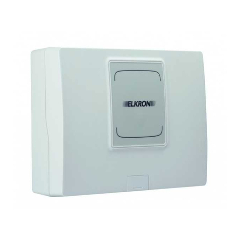
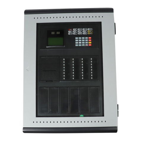
Elkron C402 User manual

1/28
Installazione MP508
DS80SC80-003D LBT80808
Installation and Programming Manual
C402 / C404
Conventional Fire Detection
Control Panel with 2 and 4
zones
GB
0051
11

2 Instal.-Progr. C402-C404
DIRECTIVE 2012/19/EU OF THE EUROPEAN PARLIAMENT AND OF THE COUNCIL of 4 July 2012 on waste
electrical and electronic equipment (WEEE)
The symbol of the crossed-out wheeled bin on the product or on its packaging indicates that this product must not be
disposed of with your other household waste.
Instead, it is your responsibility to dispose of your waste equipment by handing it over to a designated collection point for
the recycling of waste electrical and electronic equipment.
The separate collection and recycling of your waste equipment at the time of disposal will help to conserve natural resources and
ensure that it is recycled in a manner that protects human health and the environment.
For more information about where you can drop off your waste equipment for recycling, please contact your local city office, your
household waste disposal service or the shop where you purchased the product.
The information contained in this document has been collected and controlled carefully. However, the company cannot be held
responsible for any possible errors and omissions.
The company reserves the right to make, at any time and without warning, improvements and modifications to the products
described in this manual.
In this manual, you may find references and information about products (hardware or software) or services not commercialized yet.
These references and information do not imply that the company intends to commercialize these products and services.
Elkron is a trademark of URMET S.p.A.
All trademarks mentioned in this document belong to the corresponding owners.
All rights reserved. The total or partial reproduction of this document is authorised only for installation purposes of the System for
C402 and C404 stations.
Tel. +39 011.3986711 – Fax +39 011.3986703

Installation-Programming C402-C404 3
TABLE OF CONTENTS
1
GENERAL DESCRIPTION........................................................................................................................................................... 4
1.1
INTRODUCTION................................................................................................................................................................... 4
1.2
OPTIONS.............................................................................................................................................................................. 4
1.3
CE MARKING AND ACCOMPANYING DOCUMENTATION ................................................................................................ 4
2
GENERAL SAFETY MEASURES................................................................................................................................................ 5
2.1
SAFETY OF PEOPLE........................................................................................................................................................... 5
2.1.1
Installation, commissioning and maintenance operations............................................................................................ 5
2.1.2
Power supply disconnecting device ............................................................................................................................. 5
2.1.3
Batteries....................................................................................................................................................................... 5
2.1.4
Battery disposal ........................................................................................................................................................... 5
2.2
SAFETY OF THE PRODUCT................................................................................................................................................ 6
2.3
SPECIAL PRECAUTIONS .................................................................................................................................................... 6
3
INSTALLATION AND CONNECTIONS....................................................................................................................................... 7
3.1
ITEMS INCLUDED................................................................................................................................................................ 7
3.2
CONTROL PANEL INSTALLATION...................................................................................................................................... 7
3.2.1
Power supply unit terminal blocks................................................................................................................................ 8
3.2.2
Control panel card terminal boards.............................................................................................................................. 9
3.2.3
Fuses and jumpers .................................................................................................................................................... 10
3.3
BATTERIES INSTALLATION.............................................................................................................................................. 10
3.4
INSTALLATION OF THE OPTIONAL RELAY CARD.......................................................................................................... 11
3.4.1
MR402 – MR404 module of the terminal board......................................................................................................... 12
3.5
SYSTEM START-UP........................................................................................................................................................... 13
3.5.1
Functional test............................................................................................................................................................ 13
4
COMMANDS AND INDICATORS.............................................................................................................................................. 14
4.1
KEYPAD.............................................................................................................................................................................. 14
4.2
INDICATOR LIGHTS (LEDS).............................................................................................................................................. 15
5
SIGNALLING OUTPUTS AND RELAYS................................................................................................................................... 16
5.1
SIREN OUTPUT.................................................................................................................................................................. 16
5.2
FAULT RELAY .................................................................................................................................................................... 16
5.3
OPTIONAL RELAY CARD .................................................................................................................................................. 16
6
ACCESS LEVEL........................................................................................................................................................................ 17
6.1
ACCESS LEVEL 1............................................................................................................................................................... 17
6.2
ACCESS LEVEL 2............................................................................................................................................................... 18
7
PROGRAMMING ....................................................................................................................................................................... 19
7.1
ACCESS TO PROGRAMMING........................................................................................................................................... 19
7.2
ZONE OPERATING MODE................................................................................................................................................. 19
7.2.1
Display of the zone operating mode........................................................................................................................... 19
7.2.2
Programming of the zone operating mode................................................................................................................. 19
7.3
LEVEL 2 PASSWORD........................................................................................................................................................ 20
7.3.1
Password display....................................................................................................................................................... 20
7.3.2
Password programming............................................................................................................................................. 20
8
TECHNICAL SPECIFICATIONS................................................................................................................................................ 21
8.1
DETECTORS ...................................................................................................................................................................... 21
8.2
DETECTION CIRCUIT........................................................................................................................................................ 21
8.3
POWER SUPPLY................................................................................................................................................................ 21
8.4
BATTERIES ........................................................................................................................................................................ 21
8.5
SUPERVISED SIREN OUTPUT.......................................................................................................................................... 22
8.6
FIELD OUTPUT................................................................................................................................................................... 22
8.7
FAULT RELAY OUTPUT..................................................................................................................................................... 22
8.8
DISTRIBUTION OF CONSUMPTIONS............................................................................................................................... 22
8.9
MR402, MR404 OPTIONAL MODULES - OUTPUT WITH RELAY..................................................................................... 22
8.10
MECHANICAL - ENVIRONMENTAL CONDITIONS....................................................................................................... 23
9
ELECTRICAL CONNECTIONS ................................................................................................................................................. 25

4 Installation-Programming C402-C404
1 GENERAL DESCRIPTION
1.1 INTRODUCTION
The fire detection control panels C402 and C404 control respectively up to 2 and 4 independent zones with a
maximum of 32 devices per zone. Each circuit is considered as an zone and can be included or excluded via a keypad
command.
The control panel has two outputs: a general alarm siren output, which is armed with at least one zone in alarm, and
another one for general fault, which is armed when a fault condition is verified on the control panel or in the zone.
The general alarm siren output can be included or excluded via the keypad. Further relay outputs are available on the
optional relay card.
It is possible, independently for each zone, to decide whether to notify the alarm condition when one (single knock) or
more (double knock) devices detect an alarm.
C402 and C404 control panels can internally host two 12V 7.2Ah batteries (RB06 type). The batteries are not supplied
with the product.
1.2 OPTIONS
Optional modules
•MR402 auxiliary card with relay output (for C402)
•MR404 auxiliary card with relay output (for C404)
1.3 CE MARKING AND ACCOMPANYING DOCUMENTATION
According to the requirements of EN54, the “CE” marking is included and contains all required data:
is a trademark of URMET S.p.A.
Via Bologna, 188/C - 10154 Torino - Italy
11
0051-CPR-0338
DoP n. 0051-CPR-0338
C402
Control and indicating equipment for fire
detection and fire alarm systems buildings
EN 54-2: 1997 + A1:2006
EN 54-4: 1997 + A1:2002 + A2:2006
100-240 V∼-15/+10%, 50/60 Hz, 1 A
Vout: 26V⎓, ± 10%, 1.6 A
Options with requirements list:
7.8 Output fire alarm device
7.12 Co-incidence detection
0051
11
0051
is a trademark of URMET S.p.A.
Via Bologna, 188/C - 10154 Torino - Italy
11
0051-CPR-0337
DoP n. 0051-CPR-0337
C404
Control and indicating equipment for fire
detection and fire alarm systems buildings
EN 54-2: 1997 + A1:2006
EN 54-4: 1997 + A1:2002 + A2:2006
100-240 V∼-15/+10%, 50/60 Hz, 1 A
Vout: 26V⎓, ± 10%, 1.6 A
Options with requirements list:
7.8 Output fire alarm device
7.12 Co-incidence detection
0051
11
0051

Installation-Programming C402-C404 5
2 GENERAL SAFETY MEASURES
2.1 SAFETY OF PEOPLE
Some general safety instructions are included and must be strictly followed.
2.1.1 Installation, commissioning and maintenance operations
Only qualified personnel must operate in the installation phase, perform any troubleshooting and, in general, carry out
any other intervention on the system or on the control panel.
These personnel must have access to the appropriate documentation, especially this manual. Not qualified personnel
must not operate on the control panel for any reason. Furthermore, it is necessary to disconnect the control panel from
the mains in advance.
2.1.2 Power supply disconnecting device
Since the control panel must be installed in a fixed way, a power supply disconnecting device with manual command is
required by the installation standards. This device must be installed by qualified personnel in an electrical cabinet that
may contain other devices if necessary; therefore, it must be properly identified.
2.1.3 Batteries
The control panel has an internal power source with two lead sealed batteries.
WARNING!
If the batteries are replaced with inappropriate ones, there is danger of explosion or fire.
Dispose of worn batteries by following the relevant instructions.
The batteries may cause risk of electric shock or burns due to high current of short circuit. It is necessary to observe
the following precautions:
•Remove watches, rings, bracelets or any other metallic object.
•Use objects with insulated handles.
•Do not place metallic tools or objects on the batteries.
RISK OF ELECTRIC SHOCK!
•Do not try to modify the wiring or connectors of the batteries. These operations can cause injuries.
2.1.4 Battery disposal
The lead batteries contain harmful substances!
When the battery life cycle finishes, they must not be disposed of with ordinary waste. Batteries must be taken to an
authorized waste recycling and disposal centre.

6 Installation-Programming C402-C404
2.2 SAFETY OF THE PRODUCT
The control panel must be installed in a fixed way. Refer to the manual section related to the installation.
•Do not place the control panel next to liquids or in an excessively humid environment.
•Do not allow liquids or foreign bodies to enter into the equipment.
•Do not obstruct the ventilation grid.
•Do not expose the control panel to sunrays or heat sources.
All the components which the product is composed of have been selected for the intended use and their
characteristics are guaranteed when the environmental conditions surrounding the enclosure are as specified for the
3K5 class of EN 60721-3-3:1995.
2.3 SPECIAL PRECAUTIONS
Strictly follow the order of the installation and connection instructions described in this manual.
Verify the indications reported on the identification plate: they must correspond to your electrical power supply and to
the power consumption.

Installation-Programming C402-C404 7
3 INSTALLATION AND CONNECTIONS
3.1 ITEMS INCLUDED
The following components are included with the product:
•2 resistors of 3300Ωfor detection circuits termination (for C402)
•4 resistors of 3300Ωfor detection circuits termination (for C404)
•1 resistor of 3300Ωfor siren output termination
•3 clamps for cables
•Protective plastic cover for the power supply unit terminal blocks
•Double Faston cable for batteries connection
•User manual
•Installation manual
3.2 CONTROL PANEL INSTALLATION
•Slide the cap placed at the front side downwards to open the control panel. Loosen the underlying screw and
lift the cover in ABS to unhook the bottom cover.
•If necessary, open the holes placed in the upper and/or lower part of the plastic frame if they were useful for
the entry of the cables, alternatively the holes at the bottom of the container can be used.
•Fix the control panel to the wall using the correct holes/slots placed at the bottom of the container.
•The wall fixing is carried out by using 4 self–blocking fixing plugs (max 6 mm).
•Pass the mains cables and the earth connection through the slot placed at the bottom and connect them to the
terminal blocks of the electronic power supply fixed at the bottom of the container, adhering to the phase,
earth and neutral indications.
•For the power cable, a manually operated power supply switching device external to the control panel must be
used; this switching device must have a 3 mm minimum distance between contacts.
•The switching equipment must disconnect simultaneously the Line and the Neutral conductor.
•Insert the protective plastic cover of the power supply unit terminal blocks.
•Insert the clamp supplied with the control panel in the slot made in the plastic bottom and then anchor the
power supply and earth cables to the bottom of the container by tightening the clamp.
•Carry out the rest of the wiring by passing the cables from the holes on the right side of the bottom of the
container.
Once the wiring is carried out (see the following paragraphs), before connecting the mains supply, make sure that all
the cables and the corresponding braiding of the screen are fixed properly and do not cause short-circuits. Provide
power supply to the control panel and proceed to its programming by inserting the JP3 jumper.
When the programming is finished, remove the JP3 jumper, close the cover by hooking up the top part first, inserting it
into the corresponding hooks, then tighten the screw on the front side of the cover in ABS and close the cap that
covers the screw.
For the detection circuits, use the shielded cables with minimum section of 0.50mm
2
.
The resistance of the circuit should not exceed 25Ωper conductor (50Ωtotal).
The following table shows the indicative values of the maximum length of the circuit in function of the sections of the
cable used.
Section (mm
2
)
Maximum distance (m)
0.5 600
0.75 900
1.0 1200
1.5 1800
The end of line resistor (3300Ω) is connected to the output terminals of the last device. The circuits that are not used
by the control panel must be closed by using a 3300Ωresistor connected directly onto the terminals, one for each
circuit (see the system diagram).

8 Installation-Programming C402-C404
3.2.1 Power supply unit terminal blocks
A power supply unit is assembled on the control panel and is located immediately under the card.
Figure 1 – Power supply unit terminal blocks
Power supply unit terminal blocks
L Connection of the power supply cable (phase) ÷
N
Connection of the power supply cable (neutral)
Earth connection (do not remove the cable from the terminal)
-V
26.4V negative output (connection already performed – do not modify)
+V
26.4V positive output (connection already performed – do not modify)
When the wiring is finished, insert the lid that covers the terminals. See Figure 2.
Figure 2 – Closing of the lid that covers the terminals

Installation-Programming C402-C404 9
3.2.2 Control panel card terminal boards
The Control panel is equipped with a card on which 2 connector units are assembled, the "Power" group is already
pre-wired at the factory and must not be modified. The description of each terminal is described below:
BATTERY
-
Figure 3 – View of the fire detection Control panel card
Terminals services and
circuits
+PW
+24V⎓500mA field positive output
- PW Field negative output
+IC +24V⎓500mA siren positive output
- IC Siren negative output
C Fault relay output – Common contact
NC Fault relay output – Normally closed contact
NO Fault relay output – Normally open contact
+L1 Detection circuit 1 positive output
- L1 Detection circuit 1 negative output
SH Earth connection for detection circuits cable shield
+L2 Detection circuit 2 positive output
- L2 Detection circuit 2 negative output
+L3 Detection circuit 3 (*) positive output
- L3 Detection circuit 3 (*) negative output
SH Earth connection for detection circuits cable shield (*)
+L4 Detection circuit 4 (*) positive output
- L4 Detection circuit 4 (*) negative output
(*) there is no terminal in the C402 version.
“Power” terminals
Earth connection
- Power supply negative
+ Power supply positive

10 Installation-Programming C402-C404
3.2.3 Fuses and jumpers
There are protective fuses and management and programming jumpers in the control panel.
Do not replace the fuses with other fuses with different characteristics from those indicated below.
Fuses
F1 Field output protection fuse - 5x20 250V F500mA
F2 Batteries protection fuse - 5x20 250V F4A
F3 Siren output protection fuse - 5x20 250V F500mA
Jumpers
JP1 Armed
Inserted temporarily allows the control panel to be powered directly from the
batteries when there is no mains.
Not armed
Regular operation – default configuration
JP3 Armed
Programming active
Not armed
Regular operation – default configuration
3.3 BATTERIES INSTALLATION
The two batteries must be installed inside the control panel and they must be connected in series, observing the
polarity as in figure.
For connecting the batteries use the supplied cables and do not modify the existing cabling.
Batteries replacement must be performed only by qualified personnel.
Figure 4 – Placement and connection of batteries

Installation-Programming C402-C404 11
3.4 INSTALLATION OF THE OPTIONAL RELAY CARD
To install the optional module MR402 (for C402) or MR404 (for C404), proceed as follows:
•Switch off the control panel by acting on the disconnection switch, then open the container of the control panel
by removing the front cover and disconnecting the positive terminal of the batteries.
•Using light pressure, insert the 3 plastic spacers, supplied with the module, in the three holes H1, H2 and H3
of the electronic card of the control panel, making sure of their correct anchorage.
•Place the module over the 3 three plastic spacers matching with the corresponding fixing holes. Check the
correct alignment between the terminals of the electrical connector on the control panel card and the
corresponding holes in the module to allow the electrical interconnection.
•Lightly press the module to insert the plastic spacers in the H1, H2 and H3 holes of this module. Check that
the terminals of the electrical connector of the control panel are inserted correctly in the module holes.
•Perform the desired electrical connections on the module outputs.
•Reconnect the positive terminal of the batteries, close the front cover and power supply the control panel.
Figure 5 – Relay module mounting
Please note that the outputs of the optional module MR402 / MR404 cannot drive fire alarm devices (item “C”), fire
alarm routing equipment (item “E”) and fault warning routing equipment (item “J”) and cannot be connected to controls
for automatic fire protection equipment (item “G”). The items mentioned above are described in the EN54-1 standard.

12 Installation-Programming C402-C404
3.4.1 MR402 – MR404 module of the terminal board
The MR402 – MR404 modules are equipped with a group of terminals that are connected to the SPDT form C – dry
contacts of the alarm zones relays and cumulative alarm relay. Each terminal is described below:
Figure 6 – Relay module
Relay module terminals
Terminal
Description
1 Cumulative alarm relay output – normally closed contact
2 Cumulative alarm relay output – normally open contact
3 Cumulative alarm relay output – common contact
4 Alarm zone 1 relay output – normally closed contact
5 Alarm zone 1 relay output – normally open contact
6 Alarm zone 1 relay output – common contact
7 Alarm zone 2 relay output – normally closed contact
8 Alarm zone 2 relay output – normally open contact
9 Alarm zone 2 relay output – common contact
10 Alarm zone 3 relay output – normally closed contact (*)
11 Alarm zone 3 relay output – normally open contact (*)
12 Alarm zone 3 relay output – common contact (*)
13 Alarm zone 4 relay output – normally closed contact (*)
14 Alarm zone 4 relay output – normally open contact (*)
15 Alarm zone 4 relay output – common contact (*)
(*) terminal not available in the MR402 module.

Installation-Programming C402-C404 13
3.5 SYSTEM START-UP
Once the electrical connections have been carried out, it is possible to power supply and activate the control panel as
follows:
•Connect the battery terminals
•Close the plastic front side of the control panel
•Provide mains supply
•Wait for a few minutes to let the detectors perform the auto calibration
•Perform the functional test of the system and the devices
3.5.1 Functional test
Verify the circuits
•When a device is removed, the control panel must signal the opening of the circuit by activating the buzzer
and turning on the fault indicator of the corresponding zone.
If there are fault indications, check that:
•The circuit is not in short circuit
•The polarity of the circuit and the devices is correct
•The devices installed do not have excessive consumption
•The end of line resistor has been connected

14 Installation-Programming C402-C404
4 COMMANDS AND INDICATORS
4.1 KEYPAD
On the front side of the control panel there is a keypad with 8 keys, which allows the management of the control panel
based on the active level of access (to select the access level 1 or 2 refer to the “level of access” paragraph).
The description of each key is described below:
Key
Level of access 1
Level of access 2
Press briefly to turn all the indicators on.
Press for 2 seconds until the indicator
blinks to start the password entry procedure.
Press briefly to turn all the indicators on.
Press for 2 seconds until the indicator
turns off to bring the control panel to
an access level 1.
Internal buzzer silencing and events
acknowledgement.
Internal buzzer silencing and events
acknowledgement.
No action.
Puts the control panel in regular operating
conditions by cancelling any alarm and/or
fault condition.
No action.
When the control panel is in alarm
condition, briefly press to deactivate or re-
activate the siren output.
By pressing the key for 2 seconds, the
siren output is included/excluded.
1 During the password entry procedure,
number 1 is entered.
Includes or excludes the operation of
zone 1. When the zone is excluded, the
corresponding detection circuit is not
power supplied.
2 During the password entry procedure,
number 2 is entered.
Includes or excludes the operation of
zone 2. When the zone is excluded, the
corresponding detection circuit is not
power supplied.
3 During the password entry procedure,
number 3 is entered.
Includes or excludes the operation of
zone 3. When the zone is excluded, the
corresponding detection circuit is not
power supplied.
4 During the password entry procedure,
number 4 is entered.
Includes or excludes the operation of
zone 4. When the zone is excluded, the
corresponding detection circuit is not
power supplied.

Installation-Programming C402-C404 15
4.2 INDICATOR LIGHTS (LEDS)
The control panel is equipped with 24 LED indicators that allow the signalling of alarm, fault or exclusion events.
The functional description of each indicator is described below:
Indicator
Off
On
Flashing
The control panel is not power
supplied.
The control panel is power
supplied by the mains supply.
The control panel is power
supplied by the batteries
inside the unit.
No alarm condition.
Fire and siren output alarm
condition is armed.
---
No active exclusion.
There is at least one exclusion
in the control panel.
---
No fault condition.
There is a fault condition in the
control panel.
---
No fuse fault.
One of the following fuses is in
a fault condition:
Field fuse
Siren fuse
Battery fuse
---
No ground dispersion fault.
There is a ground dispersion
fault condition in the control
panel.
---
No battery fault.
There is a battery fault condition
in the control panel or the
batteries are not present.
The batteries must be
replaced.
No fault on the battery charger.
The battery charger inside the
control panel is in a fault
condition.
---
No system fault.
A fault has been detected on
the program which runs on the
control panel.
---
No fault in the siren output.
The siren output is in a fault
condition – end of line resistor is
missing (open line).
The siren output is in a fault
condition – output is in short
circuit.
No exclusion or silencing is
affecting the siren output.
The siren output is excluded
The siren output is silenced
Access level 1.
Access level 2.
Password entry procedure is
active.
Zone 1 ÷ Zone N
The zone is not in alarm
Zone 1 ÷ Zone N
If programmed in single knock
mode, the zone is in alarm
condition because at least one
device has detected an alarm.
If programmed in double knock
mode, the zone is in alarm
condition because two or more
devices have detected an
alarm.
Zone 1 ÷ Zone N
Zone in a fire alarm
condition, for single device
in alarm with double knock
mode.
Zone 1 ÷ Zone N
The zone is not in a fault
condition
Zone 1 ÷ Zone N
Zone in a fault condition – end
of line resistor is missing in the
detection circuit (open circuit)
Zone 1 ÷ Zone N
Zone in a fault condition –
detection circuit in short
circuit
Zone 1 ÷ Zone N
Non-excluded zone
Zone 1 ÷ Zone N
Excluded zone
---
N= 2 (for C402), 4 (for C404)

16 Installation-Programming C402-C404
5 SIGNALLING OUTPUTS AND RELAYS
5.1 SIREN OUTPUT
The control panel has a supervised siren output for the signalling of the alarm condition. This output is controlled
permanently by the control panel and, in case of interruption or short circuit in the connection with the siren, the control
panel generates a fault signal. The siren output, when the control panel is in an alarm condition, can be deactivated
and reactivated again.
The siren output can be excluded from its operation; in this condition, the output is neither activated nor supervised.
5.2 FAULT RELAY
The control panel is equipped with an SPDT form C – dry contact relay to signal the general fault condition managed
as follows:
•Control panel ON without any fault event: energised relay
•Control panel ON with at least one fault event: non-energised relay
•Control panel OFF: non-energised relay
The silkscreen in the card is related to the non-energised relay condition.
5.3 OPTIONAL RELAY CARD
The optional modules MR402 and MR404 are equipped with 2 or 4 outputs respectively, with an SPDT form C – dry
contact relay that makes it possible to differentiate among the signals from alarms that come from each zone.
The relay associated to a zone is activated when:
•The zone goes to alarm condition because of an alarm coming from one device
(zone programmed in single knock mode)
•The zone goes to alarm condition because of an alarm coming from two or more devices
(zone programmed in double knock mode)
On the optional modules MR402 and MR404, there is also an SPDT form C – dry contact relay output that signals an
alarm condition of any zone of the control panel.

Installation-Programming C402-C404 17
6 ACCESS LEVEL
Access levels are defined in the control panel for the protection from unwanted operation performed by non-authorised
personnel.
The access levels, as per the EN54-2: 1997 + A1: 2006 standard, are described below:
•Access level 1: it can be used by anybody who has a general responsibility of supervising. This level is active
when the access password has not been inserted and the indicator is turned OFF.
•Access level 2: it can be used by personnel having a specific responsibility in the area of security and properly
trained and authorized to operate the control panel in any of the following conditions: idle, alarm, fault and with
active exclusions. This level is active when the password has been inserted and the indicator is turned ON.
•Access level 3: it can be used by personnel properly trained and authorized for maintenance and reconfiguration
of specific data. In order to get access to the internal parts of the control panel, a proper device (screwdriver) is
required.
•Access level 4: it can be used by personnel properly trained and authorized by the manufacturer to repair the
control panel and modify its configuration. In order to get access to the internal parts of the control panel and
modify its configuration, a proper device (screwdriver) and an external equipment (not provided with the control
panel) are required.
6.1 ACCESS LEVEL 1
When the access level 1 is active in the control panel, it is possible to perform the following operations:
Indicator lights test
The key starts the test of the indicator lights and the buzzer, in order to verify their correct operation.
Acknowledge and buzzer silencing
The key allows the silencing of the buzzer. The silencing of the buzzer acts on all the alarms or active faults when
the key is pressed. This deactivates the buzzer. When new alarms or faults are verified, the buzzer will be activated
again.
When the
indicator is off, the control panel is at access level 1; when the control panel is power supplied, access
level 1 is activated.

18 Installation-Programming C402-C404
6.2 ACCESS LEVEL 2
To enter the access level 2, press the key and keep it pressed until the indicator flashes, then press the keys
1÷4 to enter the password. If a valid password is entered, the indicator will be ON permanently, indicating that the
control panel is in access level 2 (preset password at the factory: 1,1,1,1).
When access level 2 is active in the control panel, it is possible to perform the following operations:
Siren output silencing and rearm
When the control panel is in an alarm condition with the siren output armed; by pressing the key the siren is
silenced; when pressing the key again the output is rearmed. If the siren is silenced, when an alarm condition from
another zone is detected, the siren output is rearmed.
The indicator light flashes when the siren output is silenced.
Faults/alarms reset
The key cancels all the active fault and alarm conditions, placing the control panel in an idle condition. Also,
the key deactivates the siren output.
Siren output inclusion/exclusion
To exclude the siren output, press the key and keep it pressed until the indicator turns on. To include the siren
output, press the key and keep it pressed until the indicator turns off.
The status of inclusion/exclusion is saved in the non-volatile memory; in case the control panel is turned off, when
turning it on again the status is restored.
Zones inclusion/exclusion
To include or exclude the operation of every single zone, press the corresponding numerical key. When a zone is
excluded from operation, the corresponding indicator is on. The status of inclusion/exclusion is saved in the non-
volatile memory; in case the control panel is turned off, when turning it on again the status is restored.
When a zone is excluded, the corresponding detection circuit is not power supplied.
When the intervention is completed, it is recommended to restore the control panel to its regular condition of operation
with access level 1, pressing the key and keeping it pressed until the indicator turns off.

Installation-Programming C402-C404 19
7 PROGRAMMING
7.1 ACCESS TO PROGRAMMING
To access the programming, turn the control panel off, remove the front panel, disconnect the positive terminal of the
batteries and insert the JP3 jumper on the main card. Then, power supply the control panel and wait for the flashing of
indicator lights , and .
When the control panel is in the programming phase, it cannot control the detection circuits; during this phase the
control panel displays the operation modes of the zone and the password code to access level 2.
To complete the programming phase, it is necessary, with the control panel off, to remove the JP3 jumper, reconnect
the positive terminal of the batteries and close the container.
7.2 ZONE OPERATING MODE
Single knock mode
When a zone is programmed in single knock mode and the control panel is in an idle condition, when there is a
passage in alarm of a device, the control panel moves to the fire alarm condition by arming the internal buzzer, the
siren output and the optional module relays of cumulative alarm and zone.
Double knock mode
When a zone is programmed in double knock mode and the control panel is in an idle condition, when there is a
passage in alarm of a device, the control panel moves to the fire alarm condition by arming the internal buzzer and the
relays of cumulative alarm and the optional module. If another device of the same zone goes into the alarm condition,
the control panel arms the siren output and the corresponding relay of zone present in the optional module.
The control panel has, as set up in the factory, the double knock mode active in any zone.
The double knock mode is an option with requirements as per EN54-2: 1997 + A1: 2006 par. 7.12 - “Type B
dependency”.
7.2.1 Display of the zone operating mode
When the control panel is in the programming phase, the operating mode of every single zone is reported by its zone
alarm indicator:
Zone indicator off single knock mode
Zone indicator on double knock mode
7.2.2 Programming of the zone operating mode
The operating mode of every single zone can be changed when the control panel is in the programming phase; in this
condition press the numerical keys of any zone. Every time the key is pressed, the operating mode of the zone
switches between single and double knock with the immediate display of the selected mode on the corresponding
zone indicator.
The operating mode of every zone is saved in the non-volatile memory of the control panel. The information in this
memory cannot be lost when the control panel is not power supplied.

20 Installation-Programming C402-C404
7.3 LEVEL 2 PASSWORD
7.3.1 Password display
When the control panel is in the programming phase, the password made of 4 numbers is displayed on the fault and
exclusion indicators above the keys 1 – 4. The first number of the password is displayed by the indicators and
above the key 1, while the last number is displayed by the indicators and above the key 4.
The indicators and can assume the following states, therefore providing the numerical indication of the
password:
Indicator Indicator Numerical value
Off Off 1
Off On 2
On Off 3
On On 4
7.3.2 Password programming
The password of the control panel can be changed when the control panel is in the programming phase; in this
condition press the key until the indicator flashes and all the indicators , and are on. Enter the new
password by pressing the keys 1÷4: every time a key is pressed, the indicator turns off, while the corresponding
indicators and display the sequence of the number/key pressed. After entering all the four numbers, the control
panel saves the password in the non-volatile memory, the indicator turns off and displays, on the indicators above
the 1 – 4 keys, the password just programmed.
The control panel has a default password from the factory reported in the table below. It is recommended to change
the password and write it down in the appropriate “user” spaces.
Password
Number 1
Number 2
Number 3
Number 4
Factory
1 1 1 1
User
Other manuals for C402
1
This manual suits for next models
1
Table of contents
Other Elkron Control Panel manuals

Elkron
Elkron C402 User manual

Elkron
Elkron C302 User manual

Elkron
Elkron C420 Owner's manual

Elkron
Elkron FAP54 Owner's manual

Elkron
Elkron UC700-IT/SUP User manual

Elkron
Elkron FKP500 User manual

Elkron
Elkron MP500/16 Installation and operating instructions

Elkron
Elkron MP500/4N Owner's manual

Elkron
Elkron HI-Connect MP500/4 User manual

Elkron
Elkron MP500/4N Installation and operating instructions