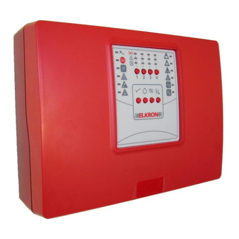
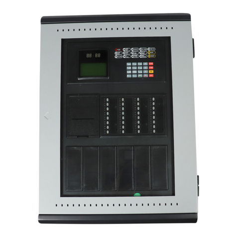
Elkron C402 User manual

1/8 Installazione MP508
DS80SC80-004A LBT80809
User Manual
C402 / C404
Conventional Fire Detection
Control Panel with 2 and 4
zones
GB
0051

2 User C402-C404
DIRECTIVE 2012/19/EU OF THE EUROPEAN PARLIAMENT AND OF THE COUNCIL of 4 July 2012 on waste
electrical and electronic equipment (WEEE)
The symbol of the crossed-out wheeled bin on the product or on its packaging indicates that this product must not be
disposed of with your other household waste.
Instead, it is your responsibility to dispose of your waste equipment by handing it over to a designated collection point for
the recycling of waste electrical and electronic equipment.
The separate collection and recycling of your waste equipment at the time of disposal will help to conserve natural resources and
ensure that it is recycled in a manner that protects human health and the environment.
For more information about where you can drop off your waste equipment for recycling, please contact your local city office, your
household waste disposal service or the shop where you purchased the product.
The information contained in this document has been collected and controlled carefully. However, the company cannot be held
responsible for any possible errors and omissions.
The company reserves the right to make, at any time and without warning, improvements and modifications to the products
described in this manual.
In this manual, you may find references and information about products (hardware or software) or services not commercialized yet.
These references and information do not imply that the company intends to commercialize these products and services.
Elkron is a trademark of URMET S.p.A.
All trademarks mentioned in this document belong to the corresponding owners.
All rights reserved. The total or partial reproduction of this document is authorised only for installation purposes of the System for
C402 and C404 stations.
Tel. +39 011.3986711 –Fax +39 011.3986703

Utente C402-C404 3
TABLE OF CONTENTS
TABLE OF CONTENTS...................................................................................................................................................................... 3
1GENERAL DESCRIPTION........................................................................................................................................................... 4
1.1 INTRODUCTION................................................................................................................................................................... 4
2NORMS........................................................................................................................................................................................ 4
3COMMANDS AND INDICATORS................................................................................................................................................ 5
3.1 KEYPAD................................................................................................................................................................................ 5
3.2 INDICATOR LIGHTS (LEDS)................................................................................................................................................ 6
4ACCESS LEVEL.......................................................................................................................................................................... 7
4.1 ACCESS LEVEL 1................................................................................................................................................................. 7
4.2 ACCESS LEVEL 2................................................................................................................................................................. 7

4 User C402-C404
1 GENERAL DESCRIPTION
1.1 INTRODUCTION
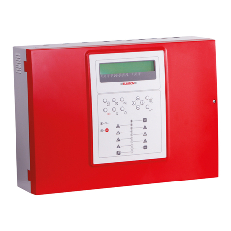
The fire detection control panels C402 and C404 control respectively up to 2 and 4 independent zones with a
maximum of 32 devices per zone. Each circuit is considered as an zone and can be included or excluded via a keypad
command.
The control panel has two outputs: a general alarm siren output, which is armed with at least one zone in alarm, and
another one for general fault, which is armed when a fault condition is verified on the control panel or in the zone.
The general alarm siren output can be included or excluded via the keypad. Further relay outputs are available on the
optional relay card.
It is possible, independently for each zone, to decide whether to notify the alarm condition when one (single knock) or
more (double knock) devices detect an alarm.
2 NORMS
In compliance with standards: EN54-2: 1997 + A1: 2006
EN54-4: 1997 + A1: 2002 + A2: 2006
Conventional fire detection control panel C402
Elkron S.p.A. 0051-CPD-0338
Conventional fire detection control panel C404
Elkron S.p.A. 0051-CPD-0337
Further information is available at the premises of the manufacturer.
0051

Utente C402-C404 5
3 COMMANDS AND INDICATORS
3.1 KEYPAD
On the front side of the control panel there is a keypad with 8 keys, which allows the management of the control panel
based on the active level of access (to select the access level 1 or 2 refer to the “level of access” paragraph).
The description of each key is described below:
Key
Level of access 1
Level of access 2
Press briefly to turn all the indicators on.
Press for 2 seconds until the indicator
blinks to start the password entry
procedure.
Press briefly to turn all the indicators on.
Press for 2 seconds until the indicator
turns off to bring the control panel to
an access level 1.
Internal buzzer silencing and events
acknowledgement.
Internal buzzer silencing and events
acknowledgement.
No action.
Puts the control panel in regular operating
conditions by cancelling any alarm and/or
fault condition.
No action.
When the control panel is in alarm
condition, briefly press to deactivate or re-
activate the siren output.
By pressing the key for 2 seconds, the
siren output is included/excluded.
1
During the password entry procedure,
number 1 is entered.
Includes or excludes the operation of
zone 1. When the zone is excluded, the
corresponding detection circuit is not
power supplied.
2
During the password entry procedure,
number 2 is entered.
Includes or excludes the operation of
zone 2. When the zone is excluded, the
corresponding detection circuit is not
power supplied.
3
During the password entry procedure,
number 3 is entered.
Includes or excludes the operation of
zone 3. When the zone is excluded, the
corresponding detection circuit is not
power supplied.
4
During the password entry procedure,
number 4 is entered.
Includes or excludes the operation of
zone 4. When the zone is excluded, the
corresponding detection circuit is not
power supplied.

6 User C402-C404
3.2 INDICATOR LIGHTS (LEDS)
The control panel is equipped with 24 LED indicators that allow the signalling of alarm, fault or exclusion events.
The functional description of each indicator is described below.
Indicatore
Spento
Acceso
Lampeggiante
The control panel is not power
supplied.
The control panel is power
supplied by the mains
supply.
The control panel is
power supplied by the
batteries inside the unit.
No alarm condition.
Fire and siren output alarm
condition is armed.
---
No active exclusion.
There is at least one
exclusion in the control
panel.
---
No fault condition.
There is a fault condition in
the control panel.
---
No fuse fault.
One of the following fuses
is in a fault condition:
Field fuse
Siren fuse
Battery fuse
---
No ground dispersion fault.
There is a ground
dispersion fault condition in
the control panel.
---
No battery fault.
There is a battery fault
condition in the control
panel or the batteries are
not present.
The batteries must be
replaced.
\
No fault on the battery
charger.
The battery charger inside
the control panel is in a
fault condition.
---
CPU
No system fault.
A fault has been detected
on the program which runs
on the control panel.
---
No fault in the siren output.
The siren output is in a fault
condition –end of line
resistor is missing (open
line).
The siren output is in a
fault condition –output is
in short circuit.
No exclusion or silencing is
affecting the siren output.
The siren output is
excluded
The siren output is
silenced
Access level 1.
Access level 2.
Password entry
procedure is active.
Zone 1 ÷ Zone N
The zone is not in alarm
Zone 1 ÷ Zone N
If programmed in single
knock mode, the zone is in
alarm condition because at
least one device has
detected an alarm.
If programmed in double
knock mode, the zone is in
alarm condition because two
or more devices have
detected an alarm.
Zone 1 ÷ Zone N
Zone in a fire alarm
condition, for single
device in alarm with
double knock mode.
Zone 1 ÷ Zone N
The zone is not in a fault
condition
Zone 1 ÷ Zone N
Zone in a fault condition –
end of line resistor is
missing in the detection
circuit (open circuit)
Zone 1 ÷ Zone N
Zone in a fault condition –
detection circuit in short
circuit
Zone 1 ÷ Zone N
Non-excluded zone
Zone 1 ÷ Zone N
Excluded zone
---
N= 2 (for C402), 4 (for C404)

Utente C402-C404 7
4 ACCESS LEVEL
Access levels are defined in the control panel for the protection from unwanted operation performed by non-authorised
personnel.
To have complete control on the control panel, you must switch from the normal access level 1 to level 2.
4.1 ACCESS LEVEL 1
When the access level 1 is active in the control panel, it is possible to perform the following operations:
Indicator lights test
The key starts the test of the indicator lights and the buzzer, in order to verify their correct operation.
Acquisizione e tacitazione buzzer
Acknowledge and buzzer silencing
The key allows the silencing of the buzzer. The silencing of the buzzer acts on all the alarms or active faults when
the key is pressed. This deactivates the buzzer. When new alarms or faults are verified, the buzzer will be activated
again.
When the indicator is off, the control panel is at access level 1; when the control panel is power supplied, access
level 1 is activated.
4.2 ACCESS LEVEL 2
To enter the access level 2, press the key and keep it pressed until the indicator flashes, then press the keys
1÷4 to enter the password. If a valid password is entered, the indicator will be ON permanently, indicating that the
control panel is in access level 2 (preset password at the factory: 1,1,1,1).
When access level 2 is active in the control panel, it is possible to perform the following operations:
Siren output silencing and rearm
When the control panel is in an alarm condition with the siren output armed; by pressing the key the siren is
silenced; when pressing the key again the output is rearmed. If the siren is silenced, when an alarm condition from
another zone is detected, the siren output is rearmed.
The indicator light flashes when the siren output is silenced.
Faults/alarms reset
The key cancels all the active fault and alarm conditions, placing the control panel in an idle condition. Also,
the key deactivates the siren output.
Siren output inclusion/exclusion
To exclude the siren output, press the key and keep it pressed until the indicator turns on. To include the siren
output, press the key and keep it pressed until the indicator turns off.
The status of inclusion/exclusion is saved in the non-volatile memory; in case the control panel is turned off, when
turning it on again the status is restored.
Zones inclusion/exclusion
To include or exclude the operation of every single zone, press the corresponding numerical key. When a zone is
excluded from operation, the corresponding indicator is on. The status of inclusion/exclusion is saved in the non-
volatile memory; in case the control panel is turned off, when turning it on again the status is restored.
When a zone is excluded, the corresponding detection circuit is not power supplied.
When the intervention is completed, it is recommended to restore the control panel to its regular condition of operation
with access level 1, pressing the key and keeping it pressed until the indicator turns off.
Other manuals for C402
1
This manual suits for next models
1
Table of contents
Other Elkron Control Panel manuals

Elkron
Elkron FAP54 User manual

Elkron
Elkron C302 User manual

Elkron
Elkron FAP54 Owner's manual

Elkron
Elkron MP500/4N Installation and operating instructions

Elkron
Elkron MP500/4N Owner's manual

Elkron
Elkron HI-Connect MP500/4 User manual

Elkron
Elkron FKP500 User manual

Elkron
Elkron MP500/4N User guide

Elkron
Elkron MP500/4N User manual

Elkron
Elkron C420 User manual