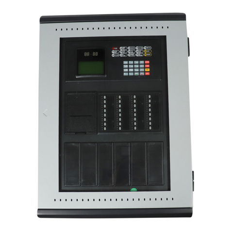
Elkron FAP54 Owner's manual

1/144 FAP54
DS80SC61-003B LBT80102
GB
Programming manual
Multiprocessor modular
control panel for fire
detection
FAP54

FAP54
2/144
All information included in this document has been collected and carefully verified; nevertheless Elkron S.p.A.
cannot be held responsible for possible mistakes and omissions.
Elkron S.p.A. reserves the right to modify or improve at any time the products described in this manual and
without notice.
It is also possible that this manual contains references or information relating to products (hardware or
software) or services not yet on the market. Such references or information do not, in any way, mean that
Elkron S.p.A. intends to sell such products or services.
© Copyright Elkron S.p.A. 2007
All rights reserved. Partial or total reproduction of this document is only authorized in order to install the
Wireless FAP54 System.
Via Cimarosa, 39 – 10154 Torino (TO) – ITALY
Tel. +39 (0)11.3986711 – Fax +39 (0)11.3986790
Office in Milan: Via Gadames, 109 – 20151 MI ; Tel: +39(0)2 334491 – Fax: +39(0)2 33449213
www.elkron.com – mail to: info@elkron.it

FAP54
3/144
1INTRODUCTION........................................................................................................................8
1.1 TERMINOLOGY.................................................................................................................................8
1.2 BASIC CONCEPTS ...........................................................................................................................9
1.3 DETECTORS, MANUAL BUTTONS AND OUTPUT MODULES......................................................9
1.4 DETECTION LINES AND CONTROL PANEL ................................................................................10
1.5 ZONE................................................................................................................................................10
1.6 GROUP OF POINTS........................................................................................................................11
1.7 GROUP OF ZONES.........................................................................................................................11
1.8 OPERATING MODES OF ZONES AND GROUPS .........................................................................12
1.9 ALARM CONDITION MODES OF ZONES AND GROUPS ............................................................12
2OPERATING MODES..............................................................................................................14
2.1 SCANNING PHASE.........................................................................................................................14
2.1.1 ALARM DISPLAY........................................................................................................................................15
2.1.2 GENERAL FAULT DISPLAY ......................................................................................................................16
2.1.3 FIELD FAULT DISPLAY .............................................................................................................................16
2.1.4 EXCLUSION DISPLAY ...............................................................................................................................17
2.1.5 MAINTENANCE DISPLAY..........................................................................................................................17
2.1.6 SLAVE CONTROL PANEL DISPLAY.........................................................................................................18
2.1.7 GENERIC EVENTS DISPLAY....................................................................................................................19
2.1.8 USER’S INFORMATION DISPLAY.............................................................................................................19
2.1.9 ACQUISITION OF ALARM, FAULT OR MAINTENANCE EVENT.............................................................19
2.1.10 GLOBAL RESET.........................................................................................................................................19
2.1.11 PROGRAMMING PHASE...........................................................................................................................19
2.2 FAP54 - MODULAR STRUCTURE..................................................................................................20
2.3 EMERGENCY OPERATION............................................................................................................21
2.4 INDICATORS, KEYS, RELAYS, JUMPERS ...................................................................................21
2.4.1 FRONT SIDE INDICATORS .......................................................................................................................21
2.4.2 KEYS (Tot 26).............................................................................................................................................22
2.4.3 OUTPUTS AND RELAYS...........................................................................................................................23
2.4.4 JUMPERS...................................................................................................................................................23
2.5 MODEM (OPTIONAL)......................................................................................................................23
2.6 MASTER AND SLAVE CONTROL PANELS (OPTIONAL) ............................................................24
2.7 CONNECTION WITH PERSONAL COMPUTER.............................................................................24
2.8 CONTROL PANEL PROGRAMMING .............................................................................................25
2.8.1 PROGRAMMING THROUGH CONTROL PANEL MENU..........................................................................25
2.8.2 PROGRAMMING VIA PC ...........................................................................................................................25
3MENU PROG– Control panel programming.........................................................................26
3.1 CIRCUIT...........................................................................................................................................27
3.1.1 CONFIGURE ALL THE CIRCUITS.............................................................................................................27
3.1.2 CONFIGURE SINGLE CIRCUIT.................................................................................................................29
3.1.3 MANUAL CIRCUIT CONFIGURATION ......................................................................................................33
3.1.4 INCLUDE/EXCLUDE...................................................................................................................................34
3.1.5 VERIFY .......................................................................................................................................................34
3.1.5.1 POINT VERIFICATION 34
3.1.5.2 POINT ADDRESSES (SINGLE LINE) 39
3.1.5.3 POINT ADDRESSES (ALL LINES) 40
3.1.5.4 CABLE LENGTH FOR LOOP MODE CIRCUITS 40
3.1.5.5 SEARCH FOR MULTIPLE ADDRESSES 40
3.1.5.6 SEARCH SHORT CIRCUIT 41
3.1.5.7 SEARCH OPEN LOOP 41
3.1.6 DELETE ALL THE ASSOCIATIONS...........................................................................................................42
FAP54
4/144
3.1.7 DELETE EXPIRED ASSOCIATIONs..........................................................................................................42
3.1.8 EVENT LOG................................................................................................................................................42
3.2 ZONE – ZONE PROGRAMMING ....................................................................................................43
3.2.1 NAME..........................................................................................................................................................43
3.2.2 ASSOCIATE POINT TO ZONE...................................................................................................................44
3.2.3 ASSOCIATE OUTPUT MODULE TO ZONE ..............................................................................................45
3.2.4 MODE..........................................................................................................................................................46
3.2.5 INCLUDE/EXCLUDE...................................................................................................................................49
3.2.6 VERIFY .......................................................................................................................................................49
3.3 GROUP PROGRAMMING ...............................................................................................................51
3.3.1 GROUP OF POINTS...................................................................................................................................51
3.3.1.1 NAME 51
3.3.1.2 ASSOCIATE POINT TO GROUP 52
3.3.1.3 ASSOCIATE OUTPUT MODULE TO GROUP 53
3.3.1.4 MODE 54
3.3.1.5 INCLUDE/EXCLUDE 56
3.3.1.6 VERIFY 56
3.3.2 GROUP OF ZONES....................................................................................................................................58
3.3.2.1 NAME 58
3.3.2.2 ASSOCIATE ZONE TO GROUP 58
3.3.2.3 ASSOCIATE OUTPUT MODULE TO GROUP 59
3.3.2.4 MODE 60
3.3.2.5 INCLUDE/EXCLUDE 62
3.3.2.6 VERIFY 63
3.4 POINT PROGRAMMING .................................................................................................................64
3.4.1 NAME..........................................................................................................................................................65
3.4.2 SET POINT (DETECTORS AND INPUT MODULES)................................................................................65
3.4.2.1 CLEAR DELAY 66
3.4.2.2 GLOBAL ALARM 66
3.4.2.3 WEIGHT 66
3.4.2.4 MEMBERSHIP TO MODULE 4I4O 67
3.4.2.5 DEFAULT 67
3.4.3 SET POINT – (OUTPUT MODULE)............................................................................................................67
3.4.3.1 SILENCE SIREN 67
3.4.3.2 GLOBAL ALARM 68
3.4.3.3 ACTIVATION 68
3.4.3.4 TYPE 68
3.4.3.5 MEMBERSHIP TO MODULE 4I4O 69
3.4.3.6 DEFAULT 69
3.4.4 INCLUDE/EXCLUDE...................................................................................................................................69
3.4.5 VERIFY .......................................................................................................................................................70
3.5 PASSWORD ....................................................................................................................................71
3.6 LANGUAGE.....................................................................................................................................72
3.7 CONFIGURE POINTS......................................................................................................................73
3.7.1 READ LOCAL DEVICE...............................................................................................................................73
3.7.1.1 OUTPUT MODULE (OM) 74
3.7.1.2 LATCH INPUT MODULE (LI) 75
3.7.1.3 PULSE INPUT MODULE (PI) 75
3.7.1.4 MANUAL BUTTON (MN) 75
3.7.1.5 CONCENTRATOR MODULE (CM) 76
3.7.1.6 BATHROOM CALL CORD (TB) 76
3.7.1.7 LATCHED INPUT WITH SIREN OUTPUT (IS) 76
3.7.1.8 GAS DETECTOR (GS) AND CURRENT INPUT MODULE 4-20 ma (CI) 77
3.7.1.9 OTHER POINTS (SM, HT, SH, etc.) 77
3.7.2 READ REMOTE DEVICE ...........................................................................................................................77
3.7.3 CONFIGURE LOCAL DEVICE ...................................................................................................................79
3.7.3.1 CONFIGURE IO MODULE (SINGLE MODULE) 79
3.7.3.2 CONFIGURE IO MODULE (MULTIPLE MODULE) 80
3.7.3.3 CONFIGURE OUTPUT MODULE (OM) 80
3.7.3.4 CONFIGURE LATCH INPUT MODULE (LI) 82
3.7.3.5 CONFIGURE PULSE INPUT MODULE (PI) 84

FAP54
5/144
3.7.3.6 CONFIGURE MANUAL BUTTON 85
3.7.3.7 ConfigurE CONCENTRATOR MODULE (CM) 86
3.7.3.8 ConfigurE BATHROOM CALL CORD (TB) 88
3.7.3.9 CONFIGURE LATCHED INPUT WITH SIREN OUTPUT (is) 88
3.7.3.10 ConfigurE GAS DETECTOR (gs) AND CURRENT INPUT MODULE 4-20 ma (ci) 90
3.7.3.11 CONFIGURE THE OTHER TYPES OF DEVICES 92
3.7.3.12 SAVE CONFIGURATION 93
3.7.4 CONFIGURE REMOTE DEVICE................................................................................................................93
3.7.5 UPDATE DEVICE .......................................................................................................................................94
3.7.6 VERIFY TYPE MATCHES..........................................................................................................................95
3.7.7 DEVICE REPLACEMENT...........................................................................................................................96
3.8 MISCELLANEOUS ..........................................................................................................................97
3.8.1 PRINTER.....................................................................................................................................................98
3.8.2 COMMUNICATIONS...................................................................................................................................99
3.8.2.1 PC PROGRAMMING 99
3.8.2.2 MODEM (OPTIONAL) 99
3.8.2.3 PANEL ID 105
3.8.2.4 MASTER / SLAVE 105
3.8.2.5 ETHERNET PORT 108
3.8.3 REMOTE CONTROL UNIT.......................................................................................................................110
3.8.3.1 INSERT LCD ANNUNCIATOR 110
3.8.3.2 DELETE 111
3.8.3.3 INCLUDE/EXCLUDE 111
3.8.3.4 VERIFY 112
3.8.4 PANEL.......................................................................................................................................................112
3.8.5 CLOCK......................................................................................................................................................113
3.8.6 OUTPUTS AND RELAYS.........................................................................................................................113
3.8.6.1 SIREN OUTPUT 113
3.8.6.2 SIREN RELAY AND FAULT RELAY 113
3.8.6.3 PROGRAMMABLE RELAY (AC/EXCLUSION) 114
3.8.7 ALARM TIMERS .......................................................................................................................................115
3.8.7.1 ALARM VERIFICATION TIME 115
3.8.7.2 HOTEL RELOAD TIME 115
4SERVICE MENU....................................................................................................................116
4.1 MAINTENANCE.............................................................................................................................117
4.1.1 SET TIME/INTERVAL...............................................................................................................................117
4.1.2 MAINTENANCE NOW ..............................................................................................................................117
4.1.3 VERIFY BY LEVEL ...................................................................................................................................118
4.1.4 VERIFICATION BY ADDRESS.................................................................................................................119
4.2 CLOCK...........................................................................................................................................120
4.3 EVENT LOG...................................................................................................................................120
4.4 PRINT EVENT LOG.......................................................................................................................122
4.5 NIGHT/DAY TIME-TABLE.............................................................................................................122
4.5.1 SET TIME-TABLE.....................................................................................................................................123
4.5.2 CONFIGURATION....................................................................................................................................123
4.5.3 VERIFY .....................................................................................................................................................123
4.6 LEVELS..........................................................................................................................................124
4.7 TEST ..............................................................................................................................................124
4.7.1 ZONE TEST..............................................................................................................................................124
4.7.2 LAMP TEST ..............................................................................................................................................125
4.7.3 POINT TEST.............................................................................................................................................125
4.7.3.1 START POINT TEST 125
4.7.3.2 STOP POINT TEST 126
4.7.3.3 VIEW TEST DATA 127
4.7.3.4 VIEW ALARM DATA 128
4.8 FW VERSIONS ..............................................................................................................................129
5SYSTEM TEST......................................................................................................................130

FAP54
6/144
6INCLUDE/EXCLUDE BUTTON.............................................................................................131
7TECHNICAL AND ENVIRONMENTAL CHARACTERISTICS ..............................................132
8APPENDIXES........................................................................................................................133
8.1 APPENDIX 1 – ERROR CODES FOR FAULT OF POINTS..........................................................133
8.2 APPENDIX 2 – FAULT CODES FOR LINE CIRCUIT CARDS .....................................................134
8.3 APPENDIX 3 – FAULT CODES FOR THE COMMAND AND CONTROL MODULE....................135
8.4 APPENDIX 4 – FAULT CODES FOR THE LCD ANNUNCIATORS .............................................135
8.5 APPENDIX 5 – FAULT CODES FOR MODEM .............................................................................135
8.6 APPENDIX 6 – SYSTEM ERROR CODES....................................................................................136
8.7 APPENDIX 7 – FAULT CODES FOR SLAVE CONTROL PANELS.............................................137
8.8 APPENDIX 8 – PROCEDURE ERROR CODES ...........................................................................138
8.9 APPENDIX 9 – LINE FAULT BITMAPS........................................................................................141
8.10 APPENDIX 10 – POINT TYPES ....................................................................................................141
8.11 APPENDIX 11 – QUALIFIER OF POINT ATTRIBUTES...............................................................142
8.12 APPENDIX 12 – ALARM TYPES ..................................................................................................142
8.13 APPENDIX 13 – ZONE TYPES .....................................................................................................142
8.14 APPENDIX 14 – ERROR CODES FOR PRINTER MODULE .......................................................143
8.15 APPENDIX 15: PS2 KEYBOARD MAPPING................................................................................143

FAP54
7/144
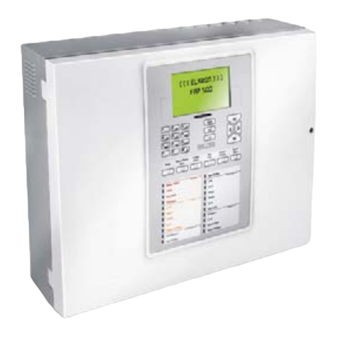
General description
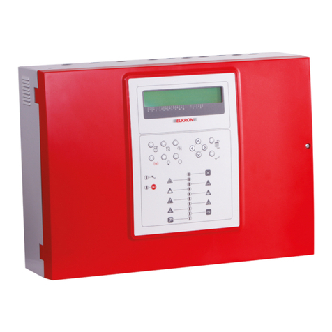
FAP54 is a modular control panel with a basic configuration, but its peripherals and functions can
be further expanded. The control panel has 2 loops which can be increased to 4 and it can be
interfaced with the outer world (PC, MODEM, LCD ANNUNCIATORS, LAN).
The microprocessor based control panel has the following functions:
•USB port for control panel configuration by PC
•Data base with programming data and event log.
The possible expansion cards, which can be inserted directly on the board, are the following:
•PSTN/GSM MODEM
•LAN interface card
•RS485 port (optoinsulated) for MASTER/SLAVE functions (optional)
•Printer connection
The possible upgrades to enable high system loads are the following:
•18Ah batteries instead of 12Ah batteries
•150W power supply module instead of 100W power supply module

FAP54
8/144
1 INTRODUCTION
1.1 TERMINOLOGY
In order to make clear what is going to be explained in this document, we are giving a definition of the
terminology used throughout the document.
Actuator = addressed output module connected to the detection line which is controlled by the control
panel in case of alarm or fault. The actuator can be configured to control: an alarm box (type “C”), a fire
fighting apparatus (type “G”) or a fault warning device (type “J”).
Adaptation = adjustment of the opacity average value detected by the smoke detector. Adaptation is
required to adjust detection as a consequence of to the progressive accumulation of dirt inside the smoke
analysis chamber.
Alarm 1 only mode = when the control panel is in idle condition and detects one or more alarm points, it
switches to the alarm state with the siren output disabled. If other alarms are detected, the siren output
keeps being disabled.
Detection line = physical connection between points and the control panel.
Detector = automatic detector which can detect an alarm condition when the element under control
exceeds a given alarm threshold.
Field fault = fault affecting a point or the detection line
Fire alarm zone = when an alarm condition occurs, all the output modules and relays are activated
according to the alarm level reached.
Group of points = abstract entity which allows to group detectors, manual keys and input interfaces
present on the detection lines and belonging to different or equal zones. It is useful to generate a higher
level control offering more versatility in those cases requiring a cross check.
Group of zones = abstract entity which allows to group zones to generate a higher level control offering
more versatility in those cases requiring a cross check.
Hotel (mode) = when the control panel detects a point in alarm, it switches to the alarm condition with the
siren output disabled and loads the timer Tp associated with the point into the Talm timer. As soon as Talm
expires, the control panel activates the siren output.
If another point detects an alarm beforeTalm expiration, Talm is compared with the “Hotel” timer Th. If Talm
> Th, the control panel reloads Talm with Th, otherwise no reload is performed.
Whether Talm has been reloaded or not, its expiration leads to the activation of the siren output.
Loop line (class A) = the topology of the detection line is a closed loop. Both ends of the detection line are
connected to the control panel.
Manual button = manual detector which allows the user to force an alarm condition. The default alarm
level associated with the manual button is two units.
Master Alarm = by enabling this function it is possible to activate the actuators through the GENERAL
ALARM key. The Master Alarm function can be performed, after activation, also by manual keys or when a
zone switches to the alarm condition.
Multiple knock = when the control panel is in idle condition and one or more alarm points are detected in
the same zone and the sum of their weights is below the weight assigned to that zone, the control panel
switches to the alarm condition with the siren output disabled. When the sum of the alarm point weights in
the same zone is equal to or higher than the weight of the zone, the control panel activates the siren output.
Multiple knock with delay = when the control panel is in idle condition and one or more alarm points are
detected in the same zone and the sum of their weights is below the weight of the zone, the control panel
switches to the alarm condition with the siren output disabled. When the sum of the alarm point weights in
the same zone is equal to or higher than the weight of the zone, the control panel enables the zone timer.
When this timer expires, the control panel activates the siren output.

FAP54
9/144
Multiple knock with reset = when the control panel is in idle condition and one or more alarm points are
detected in the same zone and the sum of their weights is below the weight of the zone, the control panel
switches to the alarm condition with the siren output disabled and starts the reset timer; when the sum of
the alarm point weights in the same zone is equal to or higher than the weight of the zone, the control panel
activates the siren output. When the reset timer expires, the control panel cancels the alarm condition and
returns to the idle state. This mode can be applied only to technological zones.
Night/Day = when the day mode is ON and an alarm occurs, the alarm relay is activated after the
associated delay expiration. In the case the night mode is ON, the alarm relay is activated immediately as
soon as the alarm condition is detected.
Open line (class B) = one end only of the detection line is connected to the control panel.
Point = component connected to the detection circuit which can transmit or receive information concerning
the fire detection.
Single knock = when the control panel is in idle condition and detects an alarm, it switches to the alarm
condition and activates the siren output.
Single knock with delay = when the control panel is in idle condition and detects one or more points in
alarm, it switches to the alarm condition with the siren output disabled and starts a timer. When the timer
expires, the siren output is activated.
System = set of connected devices (control panel, expansion, sirens, detectors, keypads, wiring cables,
etc.) which carry out a specific function.
The system interacts with the outside world through its inputs and outputs.
System fault = hardware fault in the control panel or the peripherals connected with it.
Technological zone = when an alarm condition occurs, all the output modules are activated according to
the alarm level reached. The self-powered siren, the external bell outputs, the relays and the alarm
indicators are never enabled though.
Weight = it is the contribution brought by the point going in alarm condition to the alarm condition of the
zone/group it belongs to. When the sum of the weights of the points in alarm belonging to the same
zone/group is equal to or higher than the one defined for that zone/group, the zone/group goes to alarm
condition and, according to its programming mode, can start its timer.
The weight of a zone in fire mode has a fixed unmodifiable value and equals 2; conversely, the weight of a
zone in technological mode can be modified. The weight of detectors is fixed and equals 1, whereas the
weight of manual push buttons is 2 (it can be downgraded to 1, though). The weight of the remaining types
of points is programmable.
Zone = geographical subdivision of the premises and environments under surveillance where one or more
points (max 32) are installed and share the signalling equipment.
1.2 BASIC CONCEPTS
Normally a fire system is composed of several physical elements (detectors, manual buttons, output
modules, detection lines,…) and abstract elements (zones, groups of points, groups of zones) which make
up a complex control and surveillance system. Therefore, it is necessary to briefly analyze the elements
making up a fire system to better understand the performances of FAP54 control panel.
1.3 DETECTORS, MANUAL BUTTONS AND OUTPUT MODULES
These points, installed on the detection lines, are subdivided into two categories:
•Detectors (smoke detectors, heat detectors, smoke-heat detectors, manual push buttons, etc.)
•Output modules (actuation modules, etc.)
When the control panel is in “field scanning” mode, the detectors constantly monitor possible alarm
conditions (smoke presence due to fire, gas or temperature increase). If a point detects an alarm condition,
it sends the alarm information to the control panel through the detection line.

FAP54
10/144
The control panel, in turn, activates the outputs associated with the alarm condition and the output modules
associated with the zone which the alarming detector belongs to. As a result, the output modules operate
other devices for managing and/or signalling the alarm condition (light plates, sirens,…).
The points which can be connected to the detection lines of FAP54 control panel are the following:
DEVICE Abbreviation
SMOKE DETECTOR SM
HEAT DETECTOR HT
OUTPUT MODULE OM
CONCENTRATOR MODULE CM
MANUAL BUTTON MN
GAS DETECTOR GS
LINEAR DETECTOR LN
SMOKE/HEAT DETECTOR SH
LATCH INPUT MODULE LI
PULSE INPUT MODULE PI
SMOKE/HEAT/GAS DETECTOR XS
BATHROOM CALL CORD TB
CURRENT INPUT MODULE 4-20 mA CI
LATCHED INPUT WITH SIREN OUTPUT IS
Each point is characterized by the following basic information:
Type = type of the device, according to the table above
Circuit = number of the circuit connected to the line where the point is located
Address = address assigned to the point
The maximum number of points which can be connected to a detection line is 128.
Moreover, FAP54 control panel makes it possible to associate a 32-character text with each device for an
easy identification.
1.4 DETECTION LINES AND CONTROL PANEL
The detection lines are wires over which communication between the points and the control panel takes
place. They are also used by the control panel to power supply the points.
The number of detection lines which can be connected to the control panel depends on the control panel
configuration and each line can be configured in loop or open mode.
If the line is configured as a loop, the wire where the points are connected “comes out and returns” to the
control panel, whereas in the case of a line configured as open the wire “comes out” without returning to the
control panel.
The control panel is equipped with circuit module cards. These modules provide the interface between the
detection lines and the control panel. They communicate directly with the devices and notify the control
panel about alarms or faults occurring on the field.
Besides, these modules are autonomous and can work also without the control panel supervision.
1.5 ZONE
The zone is an abstract entity composed of a set of detectors.
Each detector, regardless of the circuit it is connected to, can be associated with any zone. The only
limitation is that a detector can be associated with one single zone at a time. Therefore, different zones
cannot share detectors.
In theory, all the points (not output modules) of the system can be associated simultaneously to the same
zone. Nevertheless, it is good practice to associate no more than 32 points per zone, otherwise the
system would not be compliant with the standard UNI EN 54-2.
FAP54 control panel provides the user with 480 zones.
The zone 480, in theory fully usable as the other zones, in practice covers the role of temporary storage
area for the points just acquired by the panel at the end of an initialization procedure.
Therefore, it is advisable to move the points just acquired by the panel from the zone 480 to other zones
which the user intends to use. For each of these zones the limit of 32 points must not be violated.

FAP54
11/144
Also, it is possible to associate output modules with zones. These modules will be activated when the zone
goes into alarm condition (the zone goes into alarm condition when one or more detectors belonging to the
zone detects an alarm).
Up to 50 output modules can be associated with each zone, and each module can be associated with more
than one zone at the same time.
Each zone can be configured with either one of these operating modes:
- fire alarm
- technological
Each operating mode leads to a certain number of modes of activation of the alarm condition, the outputs
and the relays.
Also, It is possible to assign a 32 characters name to each zone.
1.6 GROUP OF POINTS
The group of points is an abstract entity composed of a set of detectors.
Each detector, regardless of the line it is connected to, can be associated with each group of points, without
any limitation. Each detector can be associated with as many groups of points as the user wants at the
same time. Therefore, different groups can share detectors.
FAP54 control panel provides the user with 240 groups of points.
It is possible to associate up to 50 detectors with each group of points.
Moreover, up to 50 output modules can be associated with each group of points, and each module can be
associated with more than one group at the same time.
Each group of points can be configured with either one of these operating modes:
- fire alarm
- technological
Each operating mode leads to a certain number of modes of activation of the alarm condition.
Also, It is possible to assign a 32 characters name to each group of points.
1.7 GROUP OF ZONES
The group of zones is an abstract entity composed of a set of zones.
Each zone can be associated with each group of zones, without any limitation. Each zone can be
associated with as many groups of zones as the user wants at the same time. Therefore, different groups
can share zones.
FAP54 control panel provides the user with 240 groups of zones.
It is possible to associate up to 50 zones with each group.
Moreover, up to 50 output modules can be associated with each group of zones, and each module can be
associated with more than one group at the same time.
Each group of zones can be configured with either one of these operating modes:
- fire alarm
- technological
Each operating mode leads to a certain number of modes of activation of the alarm condition.
Also, It is possible to assign a 32 characters name to each group of zones.

FAP54
12/144
1.8 OPERATING MODES OF ZONES AND GROUPS
Each zone, group of points or group of zones can be programmed with one of the following operating
modes:
Fire:when an alarm occurs, all the output modules, the siren and bell outputs, alarm relays and indicators
are enabled according to the alarm level of the control panel.
This mode is represented by the following achronym: FR.
Technological:when an alarm occurs, all the output modules are enabled according to the alarm level of
the control panel. The self-powered siren and external bell outputs are never enabled.
This mode is represented by the following achronym: TN.
1.9 ALARM CONDITION MODES OF ZONES AND GROUPS
Each zone, group of points and group of zones can be programmed to switch to the alarm condition with
the siren output enabled or not.
The siren output, in turn, is activated when one or more points detect an alarm condition or because of the
expiration of an activation timer, according to the programming mode of the zone or group.
The alarm condition with siren output disabled is characterized by:
- buzzer activated
- fire alarm LED blinking
- alarm relay activated
- siren relay deactivated
- siren output deactivated
The alarm condition with siren output enabled is characterized by:
- buzzer activated
- fire alarm LED steady ON
- alarm relay activated
- siren relay activated
- siren output activated
Single knock
When the control panel is in idle condition and detects one or more points in alarm, it switches to the alarm
condition with siren output enabled.
Single knock with time
When the control panel is idle condition and detects one or more alarm points, it switches to the alarm
condition with siren output disabled and starts an activation timer. When the timer expires, the control panel
switches to the alarm condition with siren output enabled.
Multiple knock
For zones programmed in “Fire” operating mode, the following applies:
When the control panel is in idle condition and one alarm from a point belonging to the zone is detected, the
panel switches to the alarm condition with siren output disabled. As soon as an alarm from another point of
the same zone is detected, the panel goes to the alarm condition with siren output enabled.
NOTE: when the panel is in idle condition and a manual push button is pressed, the control panel goes
directly to the alarm condition with siren output enabled.
For zones programmed in “Technological” operating mode and groups (both fire and technological), the
following applies:
when the control panel is in idle condition and one or more alarm points are detected in the same
zone/group and the sum of their weights is less than the weight assigned to the zone/group, the control
panel switches to the alarm condition with siren output disabled; when the sum of the alarm point weights in
the same zone/group is equal to or greater than the weight assigned to the zone/group, the control panel
switches to the alarm condition wth siren output enabled.

FAP54
13/144
Multiple knock with time
For zones programmed in “Fire” operating mode, the following applies:
When the control panel is in idle condition and one alarm from a point belonging to the zone is detected, the
panel switches to the alarm condition with siren output disabled. As soon as another alarm from a point of
the same zone is detected, the panel activates the timer for the activation of the siren output. When this
timer expires, the control panel switches to the alarm condition with siren output enabled.
NOTE: when the panel is in idle condition and a manual push button is pressed, the control panel switches
to the alarm condition with siren output disabled and the activation timer is started at once.
For zones programmed in “Technological” operating mode and groups (both fire and technological), the
following applies:
when the control panel is in idle condition and one or more alarms from points beloning to the same
zone/group are detected and the sum of their weights is less than the weight of the zone/group, the control
panel switches to the alarm condition with siren output disabled; when the sum of the alarm point weights in
the same zone/group is equal to or greater than the weight of the zone/group, the control panel starts the
timer for the activation of the siren output. When the timer expires, the control panel switches to the alarm
condition with siren output enabled.
Only alarm 1
This mode is only applicable to zones/groups programmed with “technological” mode.
When the control panel is in idle condition and one or more points detect an alarm, the control panel
switches to the alarm condition with siren output disabled. If further points detect an alarm, the control panel
keeps being in the state of alarm condition with siren output disabled.
Multiple knock with reset
This mode is only applicable to technological zones.
When the control panel is in idle condition and one or more alarm points are detected in the same zone and
the sum of their weights is less than the weight of the zone, the control panel switches to the alarm
condition with siren output disabled and starts the reset timer; when the sum of the alarm point weights in
the same zone is equal to or greater than the weight of the zone, the control panel switches to the alarm
condition with siren output enabled.
When the reset timer expires, the control panel cancels the alarm condition and returns to idle state.
Hotel
This mode is only applicable to zones programmed in “Fire” operating mode.
When the control panel detects a point in alarm, it switches to the alarm condition with siren output
disabled and starts the timer associated with the point Tp. If another alarm is detected by another point
before the expiration of Tp, the remaining amount of Tp s compared to the hotel reload time Th. If Tp > Th,
Tp is reloaded with Th, otherwise no reload is done. In any case, Tp keeps running and, on its expiration,
the control panel switches to the alarm condition with siren output enabled.
In the modes involving the siren output activation timer, it is possible to:
•Assign different timers to detectors and manual buttons.
•Increase the timer through the INCREASE DELAY key on the control panel keypad.
•Force the immediate expiration of the timer through the SKIP DELAY key on the control panel
keypad.
•Assign a zero value to the timer through the “Clear delay” function in the case of manual buttons and
input modules provided with this functionality.

FAP54
14/144
2 OPERATING MODES
The FAP54 control panel has two operating modes: scanning phase and programming phase. When
FAP54 is powered on, the scanning phase will be always started and maintained until the installer or the
user carries out an intervention.
2.1 SCANNING PHASE
In this operating mode the control panel monitors the detectors scattered in the field and manages the
following events:
- alarm
- general fault
- field fault
- maintenance
- exclusion
- events related to slave control panels (if the control panel is set as master)
- generic events (not classified into any of the previous categories)
Normally, if there are not active events, the display on the control panel front side shows the following
message:
The event indicator is shown when at least one event has occurred since the last time a level 2 password
has been inserted. If no event has occurred, a blinking asterisk will be displayed instead of the event
indicator.
If the control panel has not been programmed yet, the display shows the message “MONITORING NOT
POSSIBLE”.
If an event occurs, the display shows the event, along with the cumulative counters for each type of event
on the right-hand side.
Should more events occur, the display shows, in addition to the event counter increase, the first event
occurred at the top and the most recent alarm (if present) at the bottom.
The events are displayed according to the following priority:
•Zones in alarms (ZA)
•General faults (GF)
•Field faults (FF)
•Exclusion (EX)
•Group of points in alarm (GP)
•Group of zones in alarm (GZ)
•Maintenance (MN)
•Events related to SLAVE control panels (SP)
•Generic events (GE)
ALM Z002 D00 C01 P015 SM A001 >ZA003
KITCHEN DETECTOR GF000
ALM Z110 D00 C01 P018 SM A001 FF000
CORRIDOR DETECTOR EX000
Event cumulative
counters
First event occurred
Last alarm occurred
Time
N #
FIRE DETECTION SYSTEM
12/10/2008 11:50:42
FAP54-04
Date Type of control
System name Night time active Event indicator

FAP54
15/144
By using the keys ∧and ∨it is possible to change the type of event displayed (the > symbol on the right
selects the type of the event currently shown on the first two rows).
By using the keys <and > it is possible to go back and forth through the events of the selected type.
The selected event will be displayed at the top, while the most recent alarm event will be displayed at the
bottom (if at least one alarm is present) or nothing will be displayed.
2.1.1 ALARM DISPLAY
Display of Zone Alarm generated by detector/pushbutton associated with zone
Display of alarm of group of points generated by an associated point
Display of alarm of group of zones generated by an associated zone
ALM G025 D00 Z033 GP000
BOILER ROOM >GZ001
MN000
SP000
Zone name
Alarm event indicator
Group number Group delay Zone in alarm
ALM G020 D00 C01 P018 TP Q >GP001
KITCHEN DETECTOR GZ000
MN000
SP000
Point name
Alarm event indicator
Group number
Group delay
Circuit of the point in
alarm Point type
(see appendix)
Point address Point attributes
(see appendix)
>ZA001
GF000
ALM Z110 D00 C01 P018 TP Q Axxx FF000
KITCHEN DETECTOR EX000
Zone delay
Point name
Alarm event indicator
No. of zone in alarm
Circuit of the point in
alarm Point type
(see appendix)
Point address Point attributes
(see appendix)
Alarm type
(see appendix)

FAP54
16/144
2.1.2 GENERAL FAULT DISPLAY
The display of a general fault depends on the type of event occurred and it usually allows the immediate
recognition of the equipment or part of the control panel in faulty condition which can negatively affect the
system operation.
In any case, the display shows each event with all the data needed for the equipment identification (e.g.
address) and the related error code.
Example:
Note that some type of fault is notified with a self explaining message, allowing the user to immediately
understand what is going on.
Other types of fault are notified instead with a message and an error code. For a detailed explanation of
these codes, please refer to the appendixes.
2.1.3 FIELD FAULT DISPLAY
The display of a field fault depends on the type of fault.
Usually, a field fault affects a detection circuit or a device connected to this circuit.
A field fault due to a device is notified as follows:
The field fault on the detection circuit occurs when an event has changed the circuit connection structure,
like for instance the line loop breaking or a short circuit on the line.
In any case, a self-explaining message will be displayed. Below is reported an example of a field fault of
type “short circuit” affecting circuit 1.
Panel name
FAULT REMOTE PANEL 05 (01) ZA000
PANEL NAME >GF001
FF000
EX000
Type of fault Address of faulty panel Fault code
FAULT CIRCUIT 01 ZA000
SHORT CIRCUIT GF000
>FF001
EX000
Type of fault
Nr. of faulty circuit
FAULT Z020 C01 P018 TP Q F001 ZA000
KITCHEN DETECTOR GF000
>FF001
EX000
Point name
Zone which the point
belongs to
Faulty point address
Point type
(See appendix)
Circuit of faulty point
Fault type
Point attributes
(see appendix)

FAP54
17/144
2.1.4 EXCLUSION DISPLAY
During the scanning phase it is possible to know the state of the active exclusions regarding the equipment
connected with the control panel, the abstract entities (zones, groups), the devices and the detection lines.
A few examples are reported below.
Display of excluded device
Display of excluded zone
Display of excluded remote panel
2.1.5 MAINTENANCE DISPLAY
The display of a device requiring maintenance allows the immediate recognition of a smoke detector which
needs to be replaced or cleaned as it is no longer reliable. Therefore, the display will show the information
necessary to identify the device on the circuit.
EXCL. REMOTE PANEL 05 ZA000
PANEL NAME GF000
FF000
>EX001
Panel name
Type of exclusion
MAINT. Z020 C01 P018 SM GP000
KITCHEN DETECTOR GZ000
>MN001
SP000
Detector name
Relevant zone
Address of detector
under maintenance
Type of detector
Circuit of detector
under maintenance
EXCL. Z020 C01 P018 SM ZA000
KITCHEN DETECTOR GF000
FF000
>EX001
Point name
Zone which the point
belongs to
Address of excluded
point
Point type
Circuit of excluded
point
EXCL. ZONE 020 FR ZA000
FIRST FLOOR GF000
FF000
>EX001
Zone name
excluded zone number Zone type (see
appendix)

FAP54
18/144
MAINT. Z020 C01 P018 SM GP000
KITCHEN SMOKE DETECTOR GZ000
>MN001
SP000
SLAVE 050 HANGAR GP000
MAINT. Z020 C01 P018 SM GZ000
MN000
>SP001
SLAVE 050 HANGAR GP000
ACTIVE EXCLUSIONS 007 GZ000
MN000
>SP001
2.1.6 SLAVE CONTROL PANEL DISPLAY
This section is valid only if the control panel is configured as a MASTER and it is connected to a network of
SLAVE control panels.
Any event occurring on a SLAVE control panel is notified to the MASTER control panel, which shows it by
using two rows, according to the following rules:
- the first row shows the address and name of the SLAVE control panel affected by the event,
- the second row equals the first row used by the SLAVE control panel to show the event.on its own
display
For instance, suppose that the SLAVE control panel with address 50 and named “HANGAR” is affected by
a maintenance event on a smoke detector.
This SLAVE control panel, then, shows the following message on its display:
The MASTER control panel to whom the SLAVE control panel is connected shows the following
information:
This message says to the user that the smoke detector, located on circuit 1 in the SLAVE 50 and having
the address 18, requests a maintenance intervention.
Moreover, it says that the SLAVE control panel with address 50 is also named “HANGAR”.
Alarms, faults and maintenace events occurring on a SLAVE control panel are displayed on the MASTER
control panel’s display according to the aforementioned rule (address and name of the SLAVE control panel
plus the first row of the event shown in the SLAVE control panel).
The events of exclusion/inclusion occurring on a SLAVE control panel are handled in a different way:
If a SLAVE control panel is affected by at least one exclusion, the MASTER control panel shows a
message like this:
This message indicates the number of elements currently excluded on the SLAVE control panel (in the
example, there are 7 active exclusions on the SLAVE control panel).
If all the currently excluded elements are re-included, the above message is not shown anymore.
In the case the user wants to receive further information on the events occurring in the SLAVE control panel
(for instance, the name of the point requiring maintenance, or detailed information on the excluded
elements), it is necessary to get to the event log of the SLAVE control panel.
The event log of the SLAVE control panel can be accessed directly from the MASTER control panel’s
display. In order to do this, it is necessary to view any event of the SLAVE control panel of interest in the
MASTER control panel’s display and then press OK.

FAP54
19/144
EVENT NOT AVAILABLE GD000
GZ000
MN000
>SP000
NOTE: consider the following condition:
- the panel is a MASTER and it is connected to one or more SLAVE panels
- the MASTER contains local events ( (there are folders other than SP which are not empty)
- the SP folder is not empty and the events are all generated by the same SLAVE panel
- the MASTER is currently showing events from the SP folder
Under the aforementioned conditions, if the SLAVE panel undergoes a GLOBAL RESET the MASTER
switches temporarily to the following screen:
After 20 seconds, the MASTER shows the events of the first not empty local folder.
2.1.7 GENERIC EVENTS DISPLAY
The folder of generic events is suited for events which must be displayed but cannot be classified in any of
the previous categories.
They are:
- Events of block/resume of actuations for output modules
- Events related to modem connections (incoming calls, outgoing calls for alarms/faults/maintenance)
2.1.8 USER’S INFORMATION DISPLAY
In FAP54-4, FAP54-8 and FAP 54-16, it is possible to display two user messages, each one spread over 4
lines rather than the ELKRON logo.
These messages must be explicitly programmed by the user via PC in order to be displayed (the ELKRON
logo will be shown in the bottom part of the display until these user messages are programmed).
The user can program two messages: one to be displayed when the control panel in idle condition, the
other one to be displayed when an alarm/fault event is on.
2.1.9 ACQUISITION OF ALARM, FAULT OR MAINTENANCE EVENT
When an alarm, fault or maintenance event takes place, the control panel carries out all the actions
concerning the event (e.g. activation of actuators, relays, etc.), displays the event and activates the internal
buzzer with a continuous sound to signal the alarm and with an intermittent sound to signal faults and
maintenance events.
In these conditions, the user can press ACK in order to acknowledge the event and silence the buzzer.
However, the event is still present and the relevant outputs are still active.
2.1.10 GLOBAL RESET
By pressing RESET (after inserting the password, if enabled) the control panel normal operating conditions
will be restored: all the pending alarms and faults will be cancelled, while the controlled outputs and relays
will be forced back to idle condition.
At the end of this procedure, the control panel will resume the monitoring of the field.
If the cause of an event detected before RESET is still present after RESET has been pressed, the event
will be detected again. When the control panel is in programming phase, the “Global Reset” will reset only
the faults and the field monitoring will not be resumed.
Each time global reset is invoked, an event is stored in the event log.
2.1.11 PROGRAMMING PHASE
In this operating mode, the control panel can be programmed by a technician.
During the programming phase, the control panel does not perform the field monitoring and the detection
lines are powered off (there are procedures though, run by the user in the programming phase, which can
temporarily power on the detection lines).

FAP54
20/144
2.2 FAP54 - MODULAR STRUCTURE
FAP54 is a fire detection control panel with a completely modular structure which makes it possible to meet
all field requirements also in the event of further system expansion. To meet these needs, FAP54 consists
of different internal modules which can be “added” or “removed”. Below is reported a list of the modules
making up FAP54 with a description of each single one:
•CPU board:
A microcontroller based on ARM7 32-bit core managing all the control, programming and actuation
functions.
The CPU communicates with the circuit modules through an internal communication bus (RS485). This
communication bus includes all the information coming from the detection fields and the controls
transmitted from the CPU to the modules.
Control board
This board, located on the control panel bottom part, is fitted with a microprocessor (8 bit) and carries
out slave functions in relation to the CPU board, converting the serial commands received on the
internal bus into electrical commands to the outputs.
In addition, it monitors the absorption and management of the overall current to field and siren outputs.
The Control Board is fitted with the warning relays and the terminals for the connection of:
•detection lines
•LCD annunciators (enabled through an additional module)
•master slave (which can be enabled through an additional module)
•alarm outputs
•field output
•siren output
The Control Board is also fitted with 2 expansion slots, one used for the battery charger board and the
other for further expansions.
•Backplane board:
This board, located on the control panel bottom part, is electrically connected with the Control Board.
The loop cards shall be put on it (circuit modules).
•Battery charger board:
This board, fitted on the Control Board, manages the battery charge in compliance with EN54-04
•Circuit module board:
This module, inserted in a slot placed on the Backplane, is the interface between the detection line and
the CPU. It is an independent module managed internally by an 8-bit microprocessor. The purpose of
this module is to monitor the points connected to the detection line and notify the control panel about
alarm or fault events.
•AC power supply:
This function is carried out by an AC/DC converter which transforms Vac (from 98 to 264) input into
26Vcc output.
The control panels equipped with up to 4 loops are fitted with a factory AC/DC converter which can supply 3.8 A
The control panels equipped with more than 4 loops are fitted with a factory AC/DC converter which can supply 5.5 A
•Display:
It shows all the information processed by the CPU board.
Considering the type of control panel, 2 displays are possible:
•4/40 display for control panel with one single loop
•240*128 graphic display for control panels with at least two loops.
•Printer module (optional)
This module allows the connection of a parallel printer based on continuous module and ASCII
standard of Centronics type. This module is installed on the same line (485) where the LCD
annunciators are connected to and therefore requires this interface to work.
•RS232/485 module (optional):
This module must be connected to the CPU board in order to enable the communication between:
oMASTER panel and SLAVE panels
oFAP panel and the LCD annunciators
oFAP panel and the printer module
•MASTER/SLAVE module (optional):
Module which allows building a network of MASTER / SLAVE control panels. It is installed directly on
the CPU board.
•LAN module (optional):
Module which makes it possible to connect the control panel to a LAN. It is installed directly on the
CPU board.
•PSTN/GSM modem module (optional):
This module allows the FAP panel to communicate with an external modem. There are two version of
this module, according to whether the user wants to use a PSTN modem (mounted directly on the
board) or a GSM modem (exernal to the modem card).
Other manuals for FAP54
4
Table of contents
Other Elkron Control Panel manuals

Elkron
Elkron C302 User manual

Elkron
Elkron C420 User manual

Elkron
Elkron UC700-IT/SUP User manual

Elkron
Elkron HI-Connect MP500/4 User manual

Elkron
Elkron FKP500 User manual

Elkron
Elkron C402 User manual

Elkron
Elkron C420 Owner's manual

Elkron
Elkron MP500/4N Owner's manual

Elkron
Elkron MP500/4N User guide

Elkron
Elkron MP500/4N User manual
Popular Control Panel manuals by other brands

Notifier
Notifier MINIGAS Installation and programming manual

Pego
Pego 202BASE manual

Masterbuilt
Masterbuilt GF34G1M instruction sheet

Beckhoff
Beckhoff CP2912 Installation and operating instructions

Autonics
Autonics GP-MELSEC-Q Technical support manual

Steamist
Steamist TC-135 Installation and operating instructions