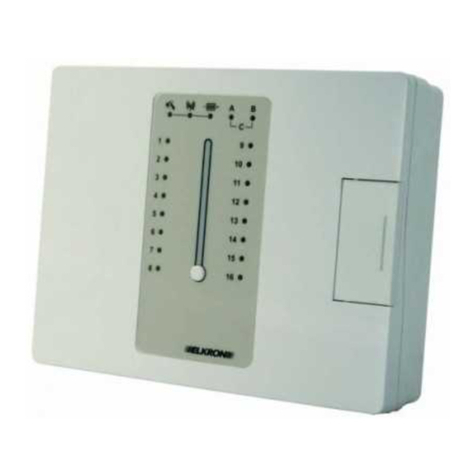
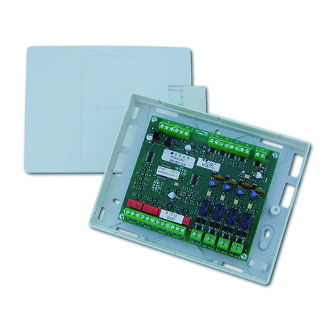
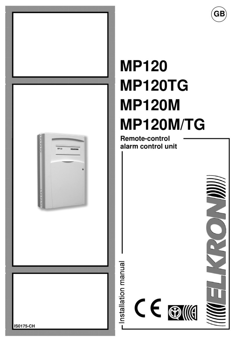
Elkron MP120 Owner's manual

IS0195-CC
Programming manual
MP120
MP120TG
MP120M
MP12
0M/TG
GB
Remote-control
alarm control unit

The information contained in this document have been collected and checked very carefully. In any case,
Elkron S.p.A. will not be responsible for any errors or omissions.
Elkron S.p.A. reserves the right to make changes or improvements to the products described in this manual at
any time and without advance notice.
In addition, this manual may contain references to or information about products or services i.e. hardware and
software items) that have not been marketed yet. Such references or information will in no case mean that
Elkron S.p.A. intend to market the aforesaid products or services.
Elkron is a registered trademark of Elkron S.p.A.
All the trademarks mentioned in this document are the property of their respective owners.
© Copyright Elkron S.p.A. 2006
All rights reserved. Full or partial printing or copying of this document is permitted only for the purpose of
installing the MP120 System.
Via G. Carducci, 3 – 10092 Beinasco TO) – ITALY
Tel. +39 0)11.3986711 – Fax +39 0)11.3499434
www.elkron.it - mailto: info@elkron.it

3/76 MP120
TABLE F C NTENTS
F REW RD ................................................................................................................................................................. 6
INTENDED USE OF THE MANUAL .......................................................................................................................... 6
STRUCTURE OF THE MANUAL .............................................................................................................................. 6
SYMBOLS AND REFERENCES ............................................................................................................................... 6
1 – C NTR L ITEMS .................................................................................................................................................. 7
1.1 KEYBOARD ............................................................................................................................................................ 7
1.2 DK2000M INSERTER ......................................................................................................................................... 8
1.3 DK3000M INSERTER ............................................................................................................................................. 8
1.4 SYSTEM STATUS INFORMATION .................................................................................................................... 9
1.4.1 stored break-in alarm displaying .................................................................................................................. 9
1.4.2 STORED tampering alarm DISPLAYING ..................................................................................................... 9
1.4.3 OPEN INPUT DISPLAYING ......................................................................................................................... 9
1.4.4 SYSTEM STATUS DISPLAYING ............................................................................................................... 10
1.5 AUTOMATIC FAILURE DISPLAYING ................................................................................................................... 10
2 – SYSTEM C MMISSI NING ................................................................................................................................ 11
2.1 SYSTEM ACCESS CODES ................................................................................................................................... 11
2.1.1 Predefined codes ........................................................................................................................................ 11
2.1.2 FunCTIONS ACCESSIBLE BY THE VARIOUS CODES ........................................................................... 11
2.2 ENTERING ALPHANUMERIC CHARACTERS THROUGH THE KEYBOARD .................................................... 12
2.3 MENU KEY FUNCTIONS .................................................................................................................................. 12
2.4 LANGUAGE SELECTION .................................................................................................................................. 13
2.5 CHOOSING THE BASE MESSAGE ON THE DISPLAY ...................................................................................... 13
2.6 SOFTWARE RELEASE ......................................................................................................................................... 13
2.7 PROGRAMMING THE INPUTS ............................................................................................................................ 14
2.7.1 TYPES OF INPUTS .................................................................................................................................... 14
2.7.2 Input encoding table ................................................................................................................................... 15
2.7.3 INPUT PROGRAMMABILITY TABLE ........................................................................................................ 16
2.7.4 ProgrammING AN INPUT .......................................................................................................................... 16
2.7.5 ProgrammING THE EXPANSION AUXILIARY INPUT .............................................................................. 17
2.8 PROGRAMMING THE OUTPUTS ........................................................................................................................ 18
2.8.1 Output specialization .................................................................................................................................. 18
2.8.2 OUTPUT ENCODING TABLE .................................................................................................................... 20
2.8.3 OUTPUT PROGRAMMING TABLE ........................................................................................................... 20
2.8.4 ProgrammING AN OUTPUT ...................................................................................................................... 20
2.9 KEYS ................................................................................................................................................................. 22
2.9.1 DK20 ........................................................................................................................................................... 22
2.9.2 DK30 ........................................................................................................................................................... 22
2.10 LPA PROGRAMMING ..................................................................................................................................... 22
2.11 CORRELATING THE SECTORS TO THE INSERTERS ................................................................................. 23
2.12 GENERAL SYSTEM TIMES ............................................................................................................................... 24
2.13 SYSTEM OPTIONS .............................................................................................................................................. 25
2.14 TELEPHONE COMMUNICATOR CONFIGURATION ...................................................................................... 26
2.14.1 ProgrammING THE TELEPHONE NUMBERS ........................................................................................ 26
2.14.2 event CORRELATION .............................................................................................................................. 27
2.14.3 event PRIORITY ....................................................................................................................................... 28
2.14.4 CALL DELAY ............................................................................................................................................ 29
2.14.5 TEST CALL .............................................................................................................................................. 29
2.14.6 CYCLIC CALL .......................................................................................................................................... 30
2.14.7 Telephone options .................................................................................................................................... 31
2.14.8 Telephone line check ............................................................................................................................... 32
2.14.9 vocal message RECORDING .................................................................................................................. 33
2.14.10 vocal message PLAYING ....................................................................................................................... 34
2.14.11 numeric MESSAGE CONFIGURATION................................................................................................. 35
2.14.12 modem TELEPHONE PARAMETERS ................................................................................................... 37
2.15 TIME PROGRAMMER P.O.) ................................................................................................................................. 38
2.15.1 OPERATING PRINCIPLES ...................................................................................................................... 38
2.15.2 TABLE ProgrammING .............................................................................................................................. 39
2.15.3 tabLE ERASING ....................................................................................................................................... 40
2.15.4 CORRELATING THE TABLES TO THE DAYS ....................................................................................... 40
2.16 PROGRAMMING THROUGH THE COMPUTER .................................................................................................... 41

4/76 MP120
2.16.1 SYSTEM REQUIREMENTS ..................................................................................................................... 41
2.17 SYSTEM TEST ................................................................................................................................................. 41
2.18 EVENT MEMORY ERASING .......................................................................................................................... 41
3 – SYSTEM MANAGEMENT .................................................................................................................................... 43
3.1 SYSTEM ACTUATION ...................................................................................................................................... 43
3.1.1 FULL ACTUATION THROUGH THE KEYBOARD .................................................................................... 43
3.1.2 FULL ACTUATION THROUGH THE electronic key oR TRANSPONDER KEY........................................ 43
3.1.3 PARTIAL ACTUATION THROUGH THE KEYBOARD .............................................................................. 44
3.1.4 PARTIAL ACTUATION THROUGH THE electronic key OR transponder KEY ......................................... 44
3.1.5 QUICK ACTUATION .................................................................................................................................. 44
3.2 DEACTIVATION ................................................................................................................................................ 45
3.2.1 Full deactivation THROUGH THE KEYBOARD ......................................................................................... 45
3.2.2 Full deactivation THROUGH THE electronic key OR THE transponder KEY............................................ 45
3.2.3 Partial deactivation THROUGH THE KEYBOARD .................................................................................... 45
3.2.4 Partial deactivation THROUGH THE electronic key oR transponder KEY ................................................ 45
3.2.5 DEACTIVATION UNDER Threat ANTI-ROBBERY) ................................................................................. 45
3.2.6 ALARM BLOCK IN PROGRESS ................................................................................................................ 46
3.2.7 ENTERING AN INVALID CODE ................................................................................................................ 46
3.3 ENABLING ........................................................................................................................................................ 46
3.3.1 access code ENABLING ............................................................................................................................ 46
3.3.2 USER CODE Reset .................................................................................................................................... 47
3.3.3 ENABLING THE Installer code ................................................................................................................... 47
3.3.4 time programmer ENABLE ......................................................................................................................... 48
3.3.5 time programmer DISABLE ........................................................................................................................ 48
3.3.6 RESPONDER ENABLE ............................................................................................................................. 48
3.3.7 RESPONDER DISABLE ............................................................................................................................ 49
3.3.8 ENABLING REMOTE CONTROL THROUGH THE MODEM .................................................................... 50
3.3.9 DISABLING REMOTE CONTROL THROUGH THE MODEM ................................................................... 50
3.3.10 ENABLING REMOTE CONTROL THROUGH THE TELEPHONE .......................................................... 50
3.3.11 DISABLING REMOTE CONTROL THROUGH THE TELEPHONE ......................................................... 51
3.3.12 ENABLING SECTOR DEACTIVATION THROUGH remotE CONTROL ................................................. 51
3.3.13 DISABLING SECTOR DEACTIVATION THROUGH remotE CONTROL ................................................ 52
3.3.14 KEY ENABLE ........................................................................................................................................... 52
3.3.15 KEY DISABLE .......................................................................................................................................... 53
3.3.16 Call-Back ENABLE ................................................................................................................................... 54
3.3.17 Call-Back DISABLE .................................................................................................................................. 54
3.4 MODIFYING THE ACCESS CODE .......................................................................................................................... 55
3.5 DATE CHANGE ..................................................................................................................................................... 55
3.6 TIME CHANGE ...................................................................................................................................................... 56
3.7 EVENT MEMORY READING ............................................................................................................................ 56
3.7.1 REFERRING TO THE EVENT MEMORY .................................................................................................. 56
3.7.2 InterpretING THE EVENT DATA ................................................................................................................ 57
3.7.3 ADDITIONAL INFORMATION FROM THE LEDS ..................................................................................... 59
3.8 TELEPHONE COMMUNICATOR................................................................................................................................ 59
3.8.1 ProgrammING A telephone number ........................................................................................................... 59
3.8.2 VOCAL CALL BLOCK ................................................................................................................................ 59
3.9 REMOTE CONTROL USER ...................................................................................................................................... 60
3.9.1 REMOTE CONTROL PROCEDURE ......................................................................................................... 60
3.9.2 bypass answer ............................................................................................................................................ 61
3.10 POSTPONING AUTOMATIC SYSTEM ACTUATION ...................................................................................... 61
3.11 KEYS ............................................................................................................................................................... 62
3.11.1 ProgrammING NEW KEYS ...................................................................................................................... 62
3.11.2 AcquiRING EXISTING KEYS ................................................................................................................... 63
3.11.3 KEY SPECIALIZATION ............................................................................................................................ 64
3.11.4 KEY CHECK ............................................................................................................................................. 65
3.11.5 ERASING ALL KEYS ............................................................................................................................... 65
3.11.6 ERASING ONE SINGLE KEY .................................................................................................................. 66
3.12 INPUT EXCLUSION AND INCLUSION ........................................................................................................... 67
3.12.1 INPUT EXCLUSION ................................................................................................................................. 67
3.12.2 INPUT INCLUSION .................................................................................................................................. 67
3.13 PERIODICAL TESTS ............................................................................................................................................ 68
3.13.1 INPUT TEST ............................................................................................................................................. 68
3.13.2 OUTPUT TEST ......................................................................................................................................... 68

5/76 MP120
4 – MENU ................................................................................................................................................................... 69
4.1 INFORMATION ABOUT THE MENUS ................................................................................................................. 69
4.2 MASTER MENU .................................................................................................................................................. 69
4.3 INSTALLER MENU ........................................................................................................................................... 70
5 – FACT RY-SET PARAMETERS .......................................................................................................................... 72
5.1 ACCESS CODES ................................................................................................................................................... 72
5.2 CONTROL UNIT INPUTS ......................................................................................................................................... 72
5.2.1 Correlated functions ................................................................................................................................... 72
5.2.2 Correlations to sectors and areas .............................................................................................................. 72
5.3 EXPANSION INPUTS 1-4) ..................................................................................................................................... 73
5.3.1 Correlated functions ................................................................................................................................... 73
5.3.2 Correlations to sectors and areas .............................................................................................................. 73
5.4 KEYBOARD INPUTS ............................................................................................................................................... 73
5.4.1 Correlated functions ................................................................................................................................... 73
5.4.2 Correlations to sectors and areas .............................................................................................................. 73
5.5 INSERTER INPUTS DK2000M) ............................................................................................................................. 74
5.5.1 Correlated functions ................................................................................................................................... 74
5.5.2 Correlations to sectors and areas .............................................................................................................. 74
5.6 OUTPUTS ......................................................................................................................................................... 74
5.6.1 Output specialization .................................................................................................................................. 74
5.6.2 PROGRAMMABLE ALARMS FOR LPA Low Power Alarm)..................................................................... 75
5.7 SYSTEM PARAMETERS ......................................................................................................................................... 75
5.8 TELEPHONE ALARM CHANNEL EVENTS ...................................................................................................... 75
5.9 TELEPHONE OPTIONS ........................................................................................................................................... 75
5.10 SYSTEM CODES ................................................................................................................................................. 75
5.11 CONTROL UNIT DIP-SWITCHES ...................................................................................................................... 75
5.12 TIME PROGRAMMER ........................................................................................................................................... 75

6/76 MP120
F REW RD
INTENDED USE F THE MANUAL
This manual has been drawn up to be used by installers, in order to provide them with the information required to
design, install and configure an antitheft system making use of the MP120 Elkron control unit.
STRUCTURE F THE MANUAL
This manual is divided into chapters. Some of the chapters may be skipped, depending on one’s knowledge and
expertise. In any case, we recommend that you read the entire manual since the latter contain useful information
that will be valuable even to the most experienced operators.
SYMB LS AND REFERENCES
For the sake of clarity, the following symbols and references are used in this manual:
separates the various keyboard entries. For instance, 120 K means “type in 120, then press OK”.
The terms written in italic, non-proportional characters indicate that they shall be replaced
with a corresponding value. For instance, if the technical access code is 000000, Technical Code K
means “type in 000000, then press OK”.
ESC , , and ENTER indicate the respective horizontal keys of the keyboard.
A , S , , E indicate the respective vertical keys of the keyboard.
Also pay attention to the symbols below:
This symbol indicates an important warning.
This symbol indicates a useful recommendation.

7/76 MP120
1 – C NTR L ITEMS
1.1 KEYB ARD
N .
Description
Use or indicat
ions provided
Further information
1 System status LED
N steady
= system fully ON
FF = system fully OFF
Slow blinking = system partially ON
1.4.4 SYSTEM STATUS
DISPLAYING
2 Maintenance LED
N steady
= system maintenance in progress
3 Time programmer P.O.)
status LED
N steady
= programmer enabled
FF = programmer disabled
Blinking = system being actuated
«Pre-actuation» will appear
on the display
4 Battery charge and
network voltage LED
N steady
= 230 V~ power supply available and
battery charged
FF = 230 V~ power supply lacking and battery
charged
Blinking = low battery charge
5 Break-in alarm memory
LED
FF
= no break-in alarm stored
Blinking = break-in alarms stored 1.4.1 stored break-in alarm
displaying
6 Tampering memory LED
FF
= no tampering alarm stored
Blinking = tampering alarms stored 1.4.2 STORED tampering
alarm DISPLAYING
7 Open input LED
Blinking
= one or several protected inputs are
open 1.4.3 OPEN INPUT
DISPLAYING
8 Disconnected input LED
FF
= no input disconnected
Blinking = one or several inputs are disconnected
9 Keyboard It is used to type in the access code, select
functions, designate inputs and program the
control unit.
10 Programming menu
navigation keys
ESC
: exits the menu same as “EXIT” button)
▼: refers to the available information
►: goes back to the beginning of the list
ENTER: confirms a choice or enters a submenu.
Note: The keyboard are always correlated to all sectors.
1
3
5
10
7
4
6
8
9
2

8/76 MP120
1.2 DK2000M INSERTER
No.
Description
Use or indications provided
Further information
1 LED Area 1
N steady
= Area 1 fully ON
FF = Area 1 fully OFF
Blinking = Area 1 partially ON
2 System status LED
N steady
= alarms stored, tampering stored, low
battery, 230 V~ power supply lacking, system faults
Slow blinking = inputs open, key programming phase
Fast blinking = pre-actuation in progress
3 LED Area 2
N steady
= Area 2 fully ON
FF = Area 2 fully OFF
Blinking = Area 2 partially ON
4 LED Area 3
N steady
= Area 3 fully ON
FF = Area 3 fully OFF
Blinking = Area 3 partially ON
5 Keyhole DK20 electronic key insertion hole
Note: Each area may represent the status of one or several sectors up to 8).
1.3 DK3000M INSERTER
No.
Description
Use or indications provided
Further information
1 LED Area 1
N steady
= Area 1 fully ON
FF = Area 1 fully OFF
Blinking = Area 1 partially ON
2 System status LED
N steady
= alarms stored, tampering stored, low
battery, 230 V~ power supply lacking, system faults
Slow blinking = inputs open, key programming phase
Fast blinking = pre-actuation in progress
3 LED Area 2
N steady
= Area 2 fully ON
FF = Area 2 fully OFF
Blinking = Area 2 partially ON
4 LED Area 3
N steady
= Area 3 fully ON
FF = Area 3 fully OFF
Blinking = Area 3 partially ON
5 Transponder Sensor for key to transponder DK30
Note: Each area may represent the status of one or several sectors up to 8).
1
3
4
5
2
1
3
4
5
2

9/76 MP120
1.4 SYSTEM STATUS INF RMATI N
When the keyboard LEDs signal any system anomaly, you can get detailed information about the source of the
trouble by following the procedure below. Access to information is free, i.e. no access code is requested.
1.4.1 ST RED BREAK-IN ALARM DISPLAYING
To display a break-in alarm signalled by the LED blinking) in detail, proceed as follows:
1. Press A . The following message will appear on the display:
where “nn” is the identification code of the input that triggered the alarm as regards the input identification
codes, refer to paragraph 2.8.2 OUTPUT ENCODING TABLE).
2. Press key ▼ several times to display other inputs if any) that triggered the alarm. When no stored alarm input
appears on the display any longer, the message below will be shown:
3. To go back to the first input stored, press ►. Press ESC to exit displaying.
Note: If key A is pressed when no alarm stored is found on the display, the «NO DATA » message will appear.
1.4.2 ST RED TAMPERING ALARM DISPLAYING
To display a tampering alarm signalled by the LED blinking) in detail, proceed as follows:
1. Press S .
2. The following message will appear on the display:
where “nn” is the identification code of the input that triggered the alarm as regards the input identification
codes, refer to paragraph 2.7.2 Input encoding table). In case of telephone line tampering, the «Telephone Line
Tampering» message will be displayed; in case of bus tampering, the «Peripheral Line Tampering» message
will appear.
3. Press key ▼ several times to display other inputs if any) that triggered the alarm. When no stored alarm input
appears on the display any longer, the message below will be shown:
4. To go back to the first input stored, press ►. Press ESC to exit displaying.
Note: If key S is pressed when no alarm stored is found on the display, the «NO DATA » message will appear.
1.4.3 PEN INPUT DISPLAYING
To display an open input signalled by the LED blinking) in detail, proceed as follows:
1. Press O .
2. The message below will appear on the display:
where “nn” is the open input identification code as regards the input identification codes, refer to paragraph
2.7.2 Input encoding table).
3. Press key ▼ several times to display other inputs if any) that triggered the alarm. When no stored alarm input
appears on the display any longer, the message below will be shown:
- -
E N D O F D A T A
- -
nn OPEN input name
- - E N D O F DA TA - -
n n M A N i np u t n a m e
- - E N D O F DA TA - -
n n A L L i np u t n a m e

10/76 MP120
4. To go back to the first input stored, press ►. Press ESC to exit displaying.
Note: If key O is pressed when no alarm stored is found on the display, the «NO DATA » message will appear.
1.4.4 SYSTEM STATUS DISPLAYING
To display the system status in detail and know what the active sectors are, proceed as follows:
1. Press ENTER.
2. The following message will appear on the display:
where the dashed line indicates an inactive sector, and the numbers if any) indicate the active sectors.
3. Press ESC to exit displaying.
Note: If the “Masking” function has been set see paragraph 2. 3 System options) and the basic message on the
display is other than “Sector displaying”, the system status will be displayed only if a valid code is entered. For
more information on sector status displaying, refer to paragraph 2.5 CHOOSING THE BASE MESSAGE ON THE
display.
1.5 AUT MATIC FAILURE DISPLAYING
When a system failure occurs, the keyboard buzzers will ring immediately, and the reason for signalling will appear
on the displays. Moreover, all the outputs programmed as “Failure” will be actuated. Since a failure may affect
correct operation of the system, these signals take priority over any other type of signal found on the display. In the
event that several types of failure occur, the individual signals will be displayed again and again by turns.
The writings on the display will disappear only after all the causes that led to failure signalling are removed. The
buzzer sound can in any case be stopped earlier by pressing key F; otherwise, it will stop after 1 minute.
Keyboard display
Failure that led to signalling
Control unit F1 Control unit fuse F1 blown. This is the fuse used to protect the inputs.
Control unit F2 Control unit fuse F2 blown. This is the fuse used to protect output U1.
Control unit F3 Control unit fuse F3 blown. This is the fuse used to protect the bus.
Expansion 1 fuse Expansion 1 fuse blown.
Expansion 2 fuse Expansion 2 fuse blown.
Expansion 3 fuse Expansion 3 fuse blown.
Expansion 4 fuse Expansion 4 fuse blown.
No control unit mains supply No mains supply 230 V~) in the control unit.
No expansion 1 mains supply No self-contained mains supply 230 V~) in expansion 1.
No expansion 2 mains supply No self-contained mains supply 230 V~) in expansion 2.
No expansion 3 mains supply No self-contained mains supply 230 V~) in expansion 3.
No expansion 4 mains supply No self-contained mains supply 230 V~) in expansion 4.
Low battery Control unit booster battery voltage lower than 11.2 V− or no battery at all).
Cont. Unit Sens. Power Supply Poor power supply for the detectors connected to the control unit.
Exp. 1 Sens. Power Supply Poor power supply for the detectors connected to expansion 1.
Exp. 2 Sens. Power Supply Poor power supply for the detectors connected to expansion 2.
Exp. 3 Sens. Power Supply Poor power supply for the detectors connected to expansion 3.
Exp. 4 Sens. Power Supply Poor power supply for the detectors connected to expansion 4.
Expansion 1 auxiliary input Expansion 1 auxiliary input alarm if programmed as generic failure).
Expansion 2 auxiliary input Expansion 2 auxiliary input alarm if programmed as generic failure).
Expansion 3 auxiliary input Expansion 3 auxiliary input alarm if programmed as generic failure).
Expansion 4 auxiliary input Expansion 4 auxiliary input alarm if programmed as generic failure).
The failure status is also signalled by the lighting of inserters red LED.
S t . S e t ._ _ _ _ _ _ __

11/76 MP120
2 – SYSTEM C MMISSI NING
2.1 SYSTEM ACCESS C DES
Up to 9 different access codes can be used to control the MP120 system: 1 Installer code, 1 Master code and 7
User codes. Each access code is made up of two parts: the user identification number i.e. the first digit) and the
personal code the remaining digits). The access code can be programmed freely, its length ranging from min. 3 to
max. 7 digits including the identification number). Depending on its type, the access code guarantees access to
certain system functions. Each user may change their own access code at will.
The Master code is always enabled and is the only one code authorized to enable the other codes. Moreover, it
can resume the factory-set value of the other access codes in the event that you forget them).
The access code must always be entered fully including the prefix) and confirmed by pressing ENTER.
Warning! If an user changes the system status (from FF to N, or vice versa, even in part), the
installer who was identified by the system will be automatically left out. The same will occur when
using the DK key.
2.1.1 PREDEFINED C DES
Identification no.
Name
Code
Correlated sectors
Enabled
0 Installer 0 00000 All YES
1 Master 1 11111 All YES
2 User 2 2 22222 Programmable NO
3 User 3 3 33333 Programmable NO
4 User 4 4 44444 Programmable NO
5 User 5 5 55555 Programmable NO
6 User 6 6 66666 Programmable NO
7 User 7 7 77777 Programmable NO
8 User 8 8 88888 Programmable NO
The installer code is enabled when the control unit leaves the manufacturing plant, and will be automatically
disabled when the system is actuated for the first time. In fact, the installer code is disabled every time the system
is actuated.
2.1.2 FUNCTI NS ACCESSIBLE BY THE VARI US C DES
Though an access code needs be entered to access the control unit functions, some functions do not require
entering a valid user code. Below is a list of this functions:
• Language displaying
• Logo displaying
• Date displaying
• Version displaying
• System status displaying
• Stored alarm displaying
• Stored tampering displaying
• Open input displaying
To access the following functions, you will have to enter any valid access code.
• Access code change
• System actuation/deactivation
• Quick actuation short code)
• Anti-coercion alarm
To access the function below, you will have to enter a valid access code other than the INSTALLER code.
• Time programmer pre-actuation.
To access the following functions, you will have to enter a valid access code that shall be either MASTER or
INSTALLER.
• Input exclusion/inclusion
• Input, output and telephone test
• Clock programming
• Key programming
• Event memory file reading
• Telephone number programming Master enabled
only to vocal call numbers)
• Call result displaying
• Message listening
• Date/time programming

12/76 MP120
To access the functions below, you will have to enter the MASTER code.
• Access codes enable
• Time programmer enable
• Remote control enable
Finally, the following system configuration functions can only be accessed by entering the INSTALLER code.
• 24h input disable with system ON central
opening)
• System parameter change.
• Input programming
• Input/sector correlation
• Inserter/sector correlation
• LPA parameter programming
• Output programming
• Entry time
• Alarm time
• ON/OFF masking
• Alarm count
• Event memory erase
• ON/OFF pre-alarm
• Mechanic key change
• Telephone communicator parameter change
• Remote assistance code programming
• Vocal message recording
• Event/channel output) correlation
• Event/telephone number correlation
• Telephone line option programming
• Numeric protocol selection
• Cyclic call timeout programming
• Telephone alarm delay programming
• Event priority programming
• Call/answer ring number programming
• Event code programming numeric protocols)
• Time programmer programming
2.2 ENTERING ALPHANUMERIC CHARACTERS THR UGH THE KEYB ARD
Alphanumeric characters can be entered through the keyboard in two instances: when you wish to store descriptive
names or when digits have to be written in the hexadecimal form e.g. 1B, 4F). Hexadecimal notation letters are
obtained by pressing the corresponding keys on the keyboard, with the equivalences below:
Keyboard key
A
S
C*
E
F
Corresponding hexadecimal character A B C D E F
To write descriptive names for users, sectors, outputs, etc.), you must use the keys that allow you to cyclically
select one or several characters, as illustrated in the table below. The point where a new character is entered is
indicated by a cursor blinking on the display. To write a name, proceed as follows:
1. press several times the key associated with the desired character until it appears;
2. press keys ► and ▼ to shift to the subsequent or preceding position use the spacer key [SPACE] to erase
unnecessary characters);
3. finally, press ENTER to store the name, or ESC if you wish to leave the procedure without storing the name.
Key
Character
Key
Characte
r
1 [space] 1 6 M N O m n o 6
2 A B C a b c 2 7 P Q R S p q r s 7
3 D E F d e f 3 8 T U V t u v 8
4 G H I g h i 4 9 W X Y Z w x y z 9
5 J K L j k l 5 0 . , : - + 0
2.3 MENU KEY FUNCTI NS
The menu keys of the KP120D keyboard perform the following functions:
ESC Goes back to the upper menu level.
▼ Goes to the next menu item.
► Goes back to the first menu item.
ENTER
• Confirms the menu item chosen and shifts to its submenu.
• Terminates and confirms data entry through the keyboard.
• Shifts to the next data item of a data sequence to be entered.
• Gains access to some menu items without the need of access codes.

13/76 MP120
2.4 LANGUAGE SELECTI N
Prior to proceeding, select the language to be used for displaying the menu items on the keyboard display. Italian is
the preset language: however, you may choose from any of the following languages: Italian, English, French,
Spanish, Portuguese, German, Swedish, Finnish, Czech, Polish and Romanian. To access the language setting
function, proceed as follows:
1. Press ENTER.
2. Press ▼ until the following message appears on the display:
3. Press ENTER to confirm.
4. The list of the available language will appear. Press ▼ to select the desired language, then press ENTER to
confirm.
5. Press EXIT to exit the menu.
2.5 CH SING THE BASE MESSAGE N THE DISPLAY
You can choose the message that will be shown on the keyboard display when the keyboard is at rest. Among the
options available are:
• ((ELKR N)) MP120;
• dd-mm-yyyy hh:mm, where “gg-mm-yyyy” indicate the day, month and year, respectively, whereas “hh:mm”
indicate the current hour and minutes, respectively both the date and time are based on the date and time set
in the control unit – refer to paragraphs 3.5 Date change and 3.6 Time change);
• dd-mm day of the week hh:mm, where “day of the week” indicates the current day Mon, Tue, Wed, etc.)
whereas “dd-mm” and “hh:mm” have the same meanings as described above.
• Vis Set _ 2 _ _ 5 _ 7 _, which displays the sector status _ = sector OFF, digit = sector ON).
• Vis Set _ █ _ _ █ _ █ _, which displays the sector status _ = sector OFF, █ = sector ON).
“Sector Displaying” features
When you choose one of the two sector status displaying modes, you will also obtain the signal for open inputs if
any). In fact, if at least one open input is found within a sector, “o” will be displayed. For instance, «Vis Set _ o _ _ _
█ _ _» indicates that sector 6 is ON, and one open input is found in sector 2.
Warning! If you choose one of the two sector status displaying modes, the “Masking” function cannot be set and,
therefore, the system status cannot be “hidden”.
To select the base message, proceed as follows:
1. Press ENTER.
2. Press ▼ until the following message appears on the display:
3. Press ENTER to confirm.
4. The list of the messages that can be shown on the display when the keyboard is at rest) will appear. Press ▼
to choose the desired message, then press ENTER to confirm.
5. Press EXIT to exit the menu.
2.6 S FTWARE RELEASE
This function allows you to display the level of the software releases for the control unit, inserters, keyboards and
system expansions. The displayed data cannot be changed.
To display the software versions, proceed as follows:
1. Press ENTER.
2. Press ▼ until the following message appears on the display
3. Press ENTER to confirm. The control unit release will appear first, in the «MP 120 A Vx.xx» format, where “x.xx”
indicates the release and sub-release.
Software Rel.
L O G O i sp la
L a n g u a ge s el ec t

14/76 MP120
4. Press ▼ to display the release levels for the other devices connected to the bus. The inserters are displayed as
«Ins.y Vxx», the keyboards are displayed as «Tas.y Vxx», and the expansions are displayed as «Esp.y Vxx»,
where “y” indicates the number of the inserter, keyboard or expansion, and “xx” indicates the software version.
5. Press EXIT to exit the menu.
2.7 PR GRAMMING THE INPUTS
2.7.1 TYPES F INPUTS
Programming the control unit and expansion alarm inputs determines the type of the control unit response to the
signals from the detector connected to the input. Among the specializations for the alarm inputs are:
• Break-in: it actuates the siren and light signals, in addition to the programmed telephone numbers and electric
outputs, when a detector signals an attempt at break-in. The break-in signalling and its respective alarm) will
come into action only when the relevant input is ON. Its operation may be:
o Instant: if the sector to which the input belongs is ON, a break-in attempt signal will immediately trigger an
alarm.
o Delayed: when an input is actuated, no alarm will be triggered until the exit time elapses, even if the
connected detector signals an attempt at break-in e.g. a door is opened, or someone steps in front of an
infrared detector): the input will merely indicate “Open Input”. When the input is ON and a detector signals an
attempt at break-in e.g. a door is opened), the entry time will be started. If the input has not been turned
OFF after the above entry time has elapsed, the control unit will cause the alarms sirens, light signals, etc.)
to be triggered. WARNING! If a door is left open when the system is actuated, the alarm will not be triggered
after only the exit time elapses: a time period equal to the exit time plus the entry time shall elapse.. In fact,
the actual break-in attempt signal will be emitted only after the exit time has elapsed from that time on, the
entry time count will be started, and the alarm will be triggered when the entry time is over).
o Final Exit: this is a Delayed operation variant and is used to actuate, almost immediately, the break-in
protection when the places to be protected are empty, thus actually cancelling the exit time delay. Moreover,
it leaves the non-“Final exit” delayed inputs out of the entry time delay provided that such inputs are the first
ones to be actuated), and actually equalizes them to the instant inputs. There is no limit to the number of
inputs that can be configured as “Final exit”. The graphic example illustrated hereinafter may help you to
better understand the “Final exit” operation.
Furthermore, the property below may be enabled to the “Break-in” inputs:
o Chime: when the sector is OFF, opening the input will actuate for 5 seconds the outputs set for the event,
including the keyboard buzzers if the sector is ON, the input opening will be managed as a break-in).
• Robbery: it will actuate only the telephone alarms the control unit must be equipped with a telephone interface)
and the preset electric outputs, without causing the sirens and visual signals to come into action. This mode
allows the user to send out a silent alarm when he/she is being threatened by the criminals, e.g. by pressing a
button or disabling, under threat, the system with the antitheft code the last digit of the code will be increased
by one unit, e.g. by typing in ...5 instead of ...4; ...9 will turn to ... 0). The input is always ON 24-h). Opening the
input will actuate the outputs set for the event for 1 minute.
• Panic: it actuates the main siren and the electric outputs preset for “Panic”. It sends out telephone alarms for
help request. The input is always ON 24-h). Opening the input will actuate the outputs set for the event for 1
minute.
• Technological: it actuates the output preset for this event. The input is always ON 24-h). Opening the input will
actuate the outputs set for the event for 1 minute.
• Fire: it actuates the output preset for this event, including the main siren if programmed). The input is always
ON 24-h). Opening the input will actuate the outputs set for the event for 1 minute.
• In/ ut: when the input is opened, it actuates the corresponding electric output as long as the input remains
open. It is ON on a 24-hour basis. By properly interfacing the lighting system and its connection to the electric
output, you may, for instance, cause the light to be turned on when an infrared detector senses people passing
by.
• Key only for the control unit inputs): it makes it possible to actuate/deactivate specific sectors correlated to the
input, and is managed only in the impulsive mode. Typical use includes actuating or deactivating, e.g. by remote
control through a radio, special sectors that can be freely correlated. The input is always ON 24-h). The “Key”
programmed inputs cannot be left out.
The expansion auxiliary inputs can be programmed only in two modes:
• Generic failure.
• Presence of network voltage: it allows you to check that the network voltage 230 V~) is always available
locally for the self-powered expansion modules with an auxiliary power supply unit.

15/76 MP120
Example of how Chime (gong) is used
The magnetic contact CM) controls the shop entrance door opening and has been
programmed with “Chime” enabled. During the working hours, when the system is
OFF, opening the door will cause the remote keyboard buzzer to ring for 5 seconds,
and will also actuate the outputs preset for “Chime”. Thus, even if you are in the
back of the shop, you will be warned that someone is getting into the shop. When
the system is ON, opening the door will instead generate a break-in alarm.
Example of how “Final exit”
is used
The place where the keyboard KP) is located is protected by an
infrared detector IR) connected to a delayed input. The entry door is
protected by a magnetic contact CM) connected to a delayed input
with “Final exit” enabled. When the system is actuated with the
keyboard, the infrared detector signals will be ignored indeed, the
exit time will be going by), thus allowing you to reach the entry door.
Subsequent opening and closing the door will reduce the remaining
exit time to 5 seconds regardless of the actual exit time left). If you
try to get in through the window when the break-in protection is ON,
the IR detector will ignore the entry time and generate a break-in
alarm immediately. On the contrary, if you get in through the door,
the magnetic contact the “Final exit” of which is enabled) will actuate
the entry time while disabling also the IR detector for the same time
period, thus allowing you to reach the keyboard and deactivate the
system.
2.7.2 INPUT ENC DING TABLE
Each input of the control unit group 0) or the expansions groups 1, 2, 3, 4) is characterized by a 2-digit code: the
first digit identifies the device, the second digit identifies the input within the device.
1
st
character
Device
2
nd
character
Input
0 Control unit 0 Tamper
1 Expansion 1 1 Input 1 *
2 Expansion 2 2 Input 2 *
3 Expansion 3 3 Input 3 *
4 Expansion 4 4 Input 4 *
5 Input 5 *
6 Input 6 *
7 Input 7 *
8 Input 8 *
9 Input 24-h) **
A Auxiliary input expansions only)
* or input tamper for dual balancing)
** or input tamper for dual balancing), control unit only
Examples of decoding
04 = control unit input 4 or input tamper, for dual balancing)
3A = expansion 3 auxiliary input
20 = expansion 2 tamper
19 = expansion 1 input 24-h)
C NTR L UNIT
SH P
BACK F THE SH P
WIND W

16/76 MP120
If the first character is either A or B, the input will belong to an inserter or a keyboard, respectively. The inputs for
the inserters and the keyboards are identified in a different way, as shown below:
A1 = inserter 1, input 1
A2 = inserter 1, input 2
A3 = inserter 2, input 1
A4 = inserter 2, input 2
A5 = inserter 3, input 1
A6 = inserter 3, input 2
A7 = inserter 4, input 1
A8 = inserter 4, input 2
B1 = keyboard 1, input 1
B2 = keyboard 1, input 2
B3 = keyboard 2, input 1
B4 = keyboard 2, input 2
B5 = keyboard 3, input 1
B6 = keyboard 3, input 2
B7 = keyboard 4, input 1
B8 = keyboard 4, input 2
BA = keyboard 1, tamper
BB = keyboard 2, tamper
BC = keyboard 3, tamper
BD = keyboard 4, tamper
2.7.3 INPUT PR GRAMMABILITY TABLE
Programmabil
ity
Control unit
Expansion
Inserter
Keyboard
Inputs active
on a 24-h
basis
Robbery ■ ■ ■ ■
Panic ■ ■ ■ ■
Fire ■ ■ ■ ■
Technological ■ ■ ■ ■
Key input ■
Break-in input
attributes
Instant ■ ■ ■ ■
Delayed ■ ■ ■ ■
Final exit ■ ■ ■ ■
Chime gong) ■ ■ ■ ■
2.7.4 PR GRAMMING AN INPUT
Warning! You must program all the system inputs to which detectors are connected.
To program an input, proceed as follows:
1. Type in the Installer code factory setting: 000000), then press ENTER twice.
2. The display will show the message below:
Press ► until the message below appears:
Then press ENTER to confirm.
3. The following message will appear on the display:
Press ENTER to confirm.
4. The first input “01”) will be shown on the display.
For each input, the display will show its numeric code, its type and its properties, if any I = instant, R = delayed,
F = Final exit, C = Chime).
5. If you wish to program a different input, select the same by means of button ▼. The inputs can also be selected
by typing in the 2-digit code corresponding to the desired input. As regards the inputs for the inserters A1...A8)
and the keyboards B1...B8), use button A to type in letter A and button S to type in letter B. If the number of the
entered input does not exist, the nearest one will be displayed.
6. Press ENTER to configure the displayed input.
0 1 : B u r g l a r n n A L L
Z o n e P ro gr am mi n g
C o n t r . P an el P R G
E v e n t M e m o r

17/76 MP120
7. The type of input will be displayed:
To modify it, press ENTER and choose another type by pressing button ▼, and confirm your choice by pressing
ENTER again.
8. WARNING! IF THE INPUT IS NOT OF THE “BREAK-IN” OR “KEY” TYPE, GO TO STEP 10.
Press ▼. The list of the sectors to which the input is correlated will appear on the display.
To modify it, press ENTER and then type in the numbers of the sectors to be correlated by typing in the number
of a sector already correlated, its correlation will be eliminated: the dash indicates a non-correlated sector). To
correlate it to all the sectors, press T TAL. End the procedure by pressing ENTER again.
9. WARNING! IF THE INPUT IS NOT OF THE “BREAK-IN” TYPE, GO TO STEP 10. Press ▼. The input operation
mode will appear on the display:
To modify it, press ENTER and choose another type by pressing button ▼, then confirm your choice by
pressing ENTER again.
10. Press ▼. The “Chime” property setting will appear on the display:
To modify it, press ENTER and choose the setting by pressing button ▼, then confirm your choice by pressing
ENTER again.
11. Press ▼. The uncoded input name or a number of dots, if the input is not available) will appear on the display:
12.
To modify it, press ENTER and use the keyboard to enter the new extended name up to 8 characters to enter
alphanumeric characters by means of the keyboard, refer to paragraph 2.2 ENTERING ALPHANUMERIC
CHARACTERS THROUGH THE keyboard). End the procedure by pressing ENTER. It is recommended that a
descriptive name is assigned to the inputs e.g. kitchen, hall, room, etc.) in order to facilitate recognition at a
later time.
13. Press ESC to go up one level in the menu.
14. Press ▼ to go to the next input to be configured start again from step 6), or press EXIT to exit the menu.
2.7.5 PR GRAMMING THE EXPANSI N AUXILIARY INPUT
The expansion auxiliary input may be programmed in two modes:
• generic failure input;
• signalling the lack of network voltage 230 V~) to the local power supply.
Warning! The “Prog.INo.aux EXP” menu item will appear only if connected expansions are available.
To program an auxiliary input, proceed as follows:
1. type in the Installer code factory setting: 000000), then press ENTER twice.
2. The message below will appear on the display:
Press ► until the following message appears:
C o n t r . P an el P R G
E v e n t M e m o r
0
1 : N a m e: . . . . . .. .
0 1 : G o n g: NO C hi m e
0 1 : M o d e: D e l a e d
0 1 : S e t .: 1 2 3 4 5 67 8
0 1 : T p e : B u r g la r

18/76 MP120
Then press ENTER to confirm.
3. The message below will appear on the display:
Press ▼ until the message below appears:
Then press ENTER to confirm.
4. The auxiliary input of the first expansion will appear. If you wish to program a different input, select it by means
of button ▼.
5. Press ENTER to configure the displayed input.
6. Use button ▼ to select the input mode Failure or NETWORK), then confirm by pressing ENTER.
7. Use button ▼ to select another input start again from step 5) or leave the menu by pressing EXIT.
2.8 PR GRAMMING THE UTPUTS
2.8.1 UTPUT SPECIALIZATI N
The electric outputs – both for the control unit and the expansions – may be programmed in order to be actuated
following certain events. On the contrary, control unit relay output U1 may be programmed only in part, as shown in
the table below.
Control unit output U1 response to the events
Event System ON System OFF
Break-in ■
Tampering ■ If programmed
Panic ■ ■
Fire If programmed If programmed
Possible electric output specializations include the following:
• Break-in: it is actuated when a detector signals an attempt at break-in in any of the correlated sectors the
sector must have been actuated. The actuation time is equal to the programmed alarm time.
• Tampering: it is actuated for 1 minute when the system detects tampering attempt at opening or removing a
device). The output is always ON 24-h).
• Robbery: the output is actuated for 1 minute directly by the user, e.g. by pressing a button or disabling, when
the user is being threatened by the criminals, the system with the antitheft code the last digit of the code will be
increased by one unit, e.g. by typing in ...5 instead of ...4; ...9 will turn to ... 0). This will allow the user to send
out a silent alarm even if he/she is being threatened. Auxiliary devices e.g. radio transmitter) may be connected
to the electric output. The input is always ON 24-h).
• Panic: it is actuated for 1 minute when an input of the “Panic” type is opened. The input is always ON 24-h).
• Technological: it is actuated for 1 minute when the detector flooding, temperature detector, etc.) for an input of
the “Technological” type signals an alarm. The input is always ON 24-h).
• Fire: it is actuated for 1 minute when the detector for an input of the “Fire” type signals the start of a fire. The
input is always ON 24-h).
• Chime: it is actuated for 5 seconds every time an anti-theft entry is open in which the “Chime” gong) property
has been enabled. The output will be enabled only when the sector is OFF.
• Failure: it is actuated when any type of failure occurs. It will remain ON until the cause of the failure is removed.
• Battery: it is actuated when the control unit booster battery voltage is lower than 11.2 V−. It will be deactivated
automatically when the battery voltage exceeds 11.2 V− again.
• Network: it is actuated when the 230 V~ network power supply is lacking for the duration established by the “No
mains supply” system parameter. It will be deactivated automatically when the mains supply is resumed.
• Telephone line status: it is actuated to signal the lack of the telephone line. Checking is carried out during line
check or tone check prior to sending out an alarm from the telephone interface. Refer to paragraph 2. 4.8
Telephone line check for further information on how the control unit carries out the line check.
• Reset: it is actuated for 5 seconds every time the system is actuated. It is used to reset the fire sensors which
will, once a fire start has been detected, remain in the alarm storage status for storing). Note: if an output is
specialized to act as a reset, the inputs powered by resettable inputs e.g.: glass breaking, smoke sensors….)
from the Reset output need be programmed as delayed inputs delay is not programmed for fire sensors).
Otherwise, upon every single actuation, these inputs will, after the sensors have been reset for 3 seconds, be
open, thus generating an alarm.
P r o g . I N o .a ux E X P
Z o n e P ro gr am mi n g
If additional expansions are
available

19/76 MP120
• Buzzer: it reproduces the keyboard buzzer signals in real time, and is used to reproduce such signals through
other devices or remotely. For instance, you may connect a more powerful sound device than the buzzer to hear
the sound even in very noisy places. WARNING! Considering that transmission on the bus may generate slight
delays, correct transfer of quick signals e.g. confirmation beeps) to the outputs controlled by remote
expansions will not be guaranteed.
• Sector TC: it is used to enable detectors and sirens. Its actuation is conditioned by the AND and OR operators
for the sectors correlated to the output. The output will surely be at rest if all the correlated sectors are OFF. If
its level is inverted, this output may be used to signal the system status, without the piece of information being
conditioned by the memory, as is the case with the output of the “System status” type. WARNING! Output 3 is
factory-set as an “Sector OR” type output, whereas output 4 is factory-set as a “Sector AND” type output.
USING THE TC UTPUT
Below are two examples of how to use the TC output, assuming that a high-power siren is to be controlled.
Example 1. Company including office and warehouse spaces: by correlating the offices and warehouses
to different sectors, you will be allowed to actuate them separately. In this case, by using an OR TC output, the
controlled siren will ring every time an attempt at break-in is made in an actuated sector, regardless of whether
the other sector is ON.
Example 2. House & garage: by correlating the house and the garage to different sectors, you will be allowed
to actuate them separately. In this case, by using an AND TC output if the garage is actuated and the house is
not e.g. people are sleeping inside the house) and an attempt at break-in is made in the garage, the
controlled siren will not ring the attempt at break-in may in any case be signalled by connecting another
sound device to a properly configured output). The controlled siren will be enabled only when both sectors are
ON no people present).
AND and OR logic functions
The AND operator assumes that all the terms in this case, the sectors) of the operation are true in this case,
active) in order for the result to be true output alarm status).
As far as the OR operator is concerned, on the contrary, it is enough that at least one of the terms is true i.e.
active) in order for the result to be true output alarm status).
The exemplifying table below may help you better understand this.
Sector st
atus
utput status
Sector 1
Sector 2
Sector 3
con AND
con R
OFF OFF OFF At rest At rest
OFF OFF ON At rest Alarm
ON OFF ON At rest Alarm
ON ON ON Alarm Alarm
• System status: it signals whether the correlated sectors are ON or OFF and whether stored alarms are
available. Signals are provided by properly changing the output status, as illustrated in the diagram below.
System OFF System ON System OFF with alarms
stored System ON with alarms
stored
• pen input ( I): it is actuated every time an input of the system is opened.
• LPA: it is actuated every time any of the alarm signals belonging to the LPA configuration is emitted. Thus, one
same output may respond to several types of alarm. Up to 8 signals may be assigned to the LPA configuration,
which will be controlled by all the outputs programmed as LPA. The alarm events that can be correlated are:
1 – Break-in
2 – Tampering
3 – Robbery
4 – Panic
5 – Technological
6 – Fire
7 – Failure
8 – Chime
• IN −> UT: the output follows the status of the corresponding input open input = output ON; closed input =
output at rest). You need not program the input: you just need to specialize the output. The inputs and outputs
make up fixed pairs, which cannot be modified. These pairs are as follows:

20/76 MP120
Control unit
Expansion 1
Expansion 2
Expansion 3
Expansion 4
Input 02 > Output 02
Input 03 > Output 03
Input 04 > Output 04
Input 05 > Output 05
Input 11 > Output 11
Input 12 > Output 12
Input 13 > Output 13
Input 14 > Output 14
Input 21 > Output 21
Input 22 > Output 22
Input 23 > Output 23
Input 24 > Output 24
Input 31 > Output 31
Input 32 > Output 32
Input 33 > Output 33
Input 34 > Output 34
Input 41 > Output 41
Input 42 > Output 42
Input 43 > Output 43
Input 44 > Output 44
• P : the output is managed by the time programmer, the commands of which specify the output actuation and
deactivation times as well as from remote location, through DTMF tones see user remote management).
• Pre-actuation: the output is managed by the time programmer. The purpose of this is to actuate optical or
sound indicators in order to signal forthcoming automatic actuation of the system. It is actuated 5 minutes prior
to the actuation command given by the time programmer.
2.8.2 UTPUT ENC DING TABLE
Every single output of the control unit group 0) or expansions groups 1, 2, 3, 4) is characterized by a 2-digit code:
the firs code identifies the device, whereas the second code identifies the input inside the device.
1
st
character
Device
2
nd
character
utput
0 Control unit 1 U1 - Output 1 *
1 Expansion 1 2 U2 - Output 2
2 Expansion 2 3 U3 - Output 3
3 Expansion 3 4 U4 - Output 4
4 Expansion 4 5 U5 - Output 5 **
* relay-type in the control unit, electric type in expansions - ** control unit only
Examples of encoding
04 = control unit output U4
21 = expansion 2 output U1
2.8.3 UTPUT PR GRAMMING TABLE
No.
Denomination
Description
U1 (control unit)
U2, U3, U4, U5
(control unit)
U1, U2,U3, U4
(expansions)
01 Break-in Break-in alarm ♦ ■
02 Tampering Tampering alarm ■ ■
03 Robbery Robbery alarm no sirens) ■
04 Panic Panic alarm ♦ ■
05 Technological Technological alarm ■
06 Fire Fire alarm ■ ■
07 Chime Chime gong) signalling ■
08 Failure Generic failure alarm ■
09 Battery Low battery alarm ■
10 Network No mains supply alarm ■
11 Telephone line status Telephone line failure alarm ■
12 Reset Glass breaking + smoke sensor reset ■
13 Buzzer Buzzer signalling ■
14 TC Correlated sector TC ■
15 System status System status STS ■
16 Open input Correlated sector open input OI) ■
17 IN −> OUT Input-output direct connection ■
18 LPA LPA alarm OR) ■
19 P.O. output Output managed both by PO and from
remote location via DTMF) ■
20 Pre-actuation Pre-actuation signalling through PO ■
♦ Predefined alarm output cannot be modified).
2.8.4 PR GRAMMING AN UTPUT
To program an output, proceed as follows:
1. Type in the Installer code factory setting: 000000), then press ENTER Twice.
2. The following message will appear on the display
Other manuals for MP120
1
This manual suits for next models
3
Table of contents
Other Elkron Control Unit manuals

Elkron
Elkron IO500 User manual

Elkron
Elkron MP 110 User manual

Elkron
Elkron PRO MEDEA/32 User manual

Elkron
Elkron MP120 User manual

Elkron
Elkron DK510M-P User manual

Elkron
Elkron IO501 User manual

Elkron
Elkron IMG500/N User manual

Elkron
Elkron IT500CLOUD User manual

Elkron
Elkron MR16 User manual

Elkron
Elkron MP 200 Manual