Elma ELMA-1336 User manual

CHROMA METER
ELMA-1336
INSTRUCTION MANUAL

CONTENTS
Title Page
1. INSTRUCTION.............................................................................1
2. FEATURES & APPLICATION.....................................................1
3. SPECIFICATIONS.......................................................................2
4. PARTS & CONTROLS ................................................................3
4-1 Description of Parts & Control keys........................................3
4-2 Description of Display.............................................................5
5. OPERATING INSTRUCTIONS....................................................7
5-1 Selecting Illuminance Unit lx or fc...........................................7
5-2 Talomg Color Measurements .................................................7
5-3 Taking Color Difference Measurement...................................8
5-4 Measuring the Correlated Color Temperature......................11
5-5 Using the Correction Factors (CF)........................................14
5-6 Manual Data Memory and Read Operations.........................16
5-7 Setting the Auto Power Off Time..........................................18
5-8 Setting the Real-Time...........................................................19
5-9 Auto Datalogging..................................................................19
5-10 Auto-Cycle Timer Datalogging............................................21
5-11 No-Cycle Timer Datalogging...............................................23
6. BATTERY CHECK-UP &REPLACEMENT .............................25
7. SPECTRAL SENSITIVITY CHARACTERISTIC........................26
8. MAINTENANCE.........................................................................26
9. SOFTWARE INSTALLATION AND OPERATION.....................26
※
Copyright ©
2014 Elma Instruments. All rights reserved.

1
1. INSTRUCTION
The digital Chroma meter is a precision instrument used to measure color
coordinate, illuminance and correlated color temperature.
It meets CIE photopic spectral response.
The Chroma meter is compact, tough and easy to handle owing to its
construction.
The light sensitive component used in the meter is a very stable, long-life
silicone photo diode and spectral response filter.
Fully functional for professional requirements.
U.S. Pat. No. Des. 446,135
2. FEATURES & APPLICATION
Triple Display, 4-digit LCD reading.
LED Color Bin select function (x,y) or (Tcp, uv). (Use CD software)
User calibration function.
User reference value setting function.
Illuminance maximum/minimum measurement function.
Data Hold function.
Data memory and read function.
Data logger function.
Auto power off function.
USB Interface.
Applications:
Measure tristimulus values, chromaticity, color difference, correlated color
temperature, and illuminance of light sources.
R&D and color inspection of light in a variety of industries such as lamp
manufacturers, building and interior design.
Set-up projectors for presentation purposes.
Adjust color of CRTs, flat panel, and other display devices.
Evaluate and control color of light boxes and light booths.

2
3. SPECIFICATIONS
Display:Triple display 4 digit LCD read out.
Measuring function:
Tristimulus values: XYZ
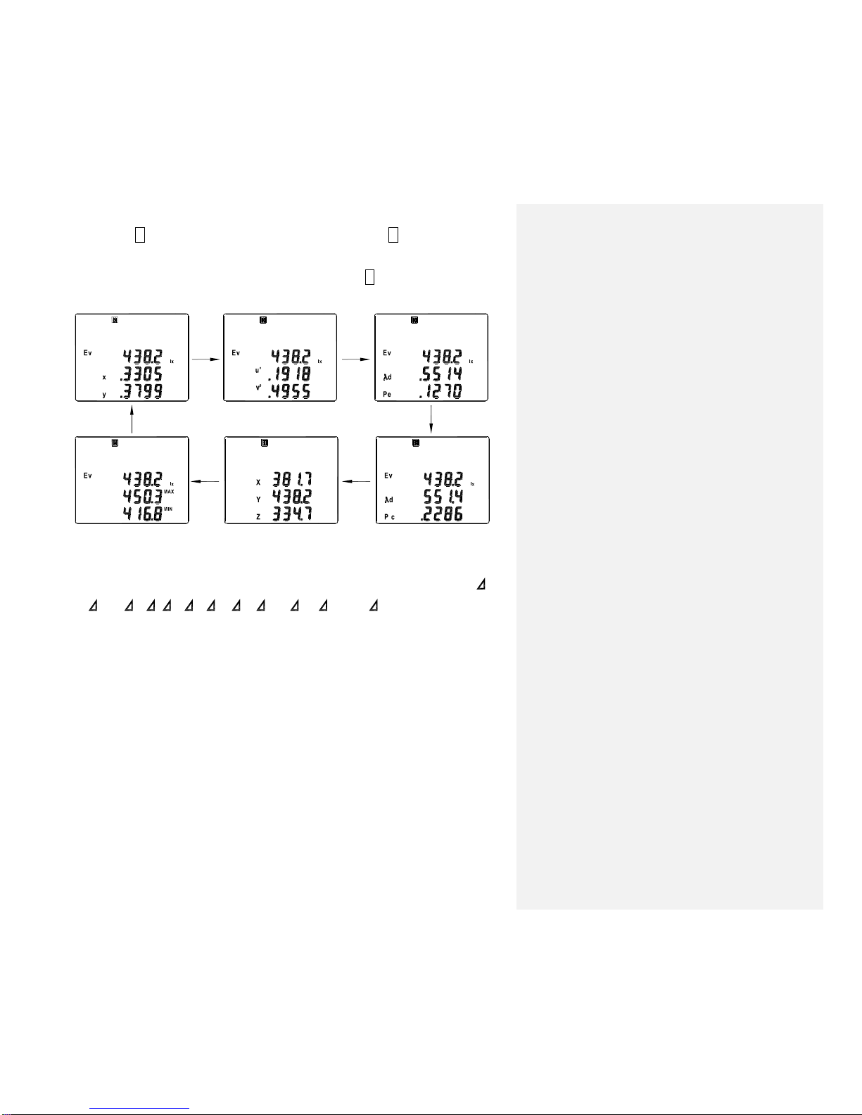
Chromaticity: (Ev, x, y); (Ev, u’, v’); (Ev, λd, Pe); (Ev, λd, Pc); (Ev, MAX, MIN).
Correlated color temperature: (Ev, Tcp, uv); ( Ev, Tcp, uv )
Color difference: ( X, Y, Z); ( Ev, x, y); ( Ev, u’, v’); ( Ev, u’v’);
( Ev, λd, Pe); ( Ev, λd, Pc)
Measuring range:0.1 to 99990 lx, 0.01 to 9999 fc (Chromaticity: 5 lx, 0.5 fcd or
above)
Accuracy:
Ev (Linearity): ±3%rdg±2dgts
xy: ±0.02 (800 lx, Standard Illuminant A measured)
Repeatability:
Ev: ±0.5%rdg±1dgt
xy: ±0.003 (800 lx, Standard Illuminant A measured)
Temperature drift:Ev: ±5%rdg±2dgts, xy: ±0.008
Humidity drift: Ev: ±3%rdg±2dgts, xy: ±0.005
CIE photopic f ’1:≦8%
Cosine response f2: ≦3%
Measuring Rate:1 sec
Photosensor:Silicon photocell
Data Memory Capacity: 80 sets. (Direct reading from LCD display)
Data Logger Capacity: microSD CARD 4GB (Maximum 200 blocks)
Operating / Storage Conditions: 0℃to 50℃<80% RH/-10℃to 60℃<70% RH
Power Source:6 pcs AAA size Battery
Battery Life (typical): 50 hours
Photosensor Lead Length: 150 cm (approx.)
Photosensor Dimensions: 92(L) ×60(W) ×29(H)mm
Dimension: 150(L) ×72(W) ×35(H)mm
Weight: Meter: 235g, Photosensor: 210g
Accessories: Carrying case, Instruction manual, Battery, CD software, USBcable.
Option Accessories: AC adaptor 9VDC 100mA.

3
4. PARTS & CONTROLS
4-1 Description of Parts & Control keys
1. LCD Display: Triple 4 digit display with a maximum of 99990 readings and the
indicating signs of measured values, unit function symbols and
decimal points etc. are displayed.
2. Power Control key: Press this key to turn on or off the meter.
3. MODE key:
Sets the meter into the color measurement mode, and switches the color
coordinates.
Press this key to circulate the reading of (Ev, x, y), (Ev, u’, v’), (Ev, λd, Pe),
(Ev, λd, Pc), (X, Y, Z) and (Ev, MAX, MIN).
4. Hkey: Press this key momentarilly to freeze or unfreeze the displayed reading.
5. key:
Sets the meter into color difference measurement mode, and switches the
color difference display.
Press this key to circulate the reading of ( Ev, x, y), ( Ev, u’, v’), (
Ev, λd, Pe), ( Ev, λd, Pc), and ( X, Y, Z).
6. SET key: Press this key to enter the setting mode.
Press key to exit this mode.

4
SET01 : Measurement illuminance unit lxor fc setting mode.
SET02 : Real time setting mode.
SET03 : Auto datalogging interval time setting mode.
SET04 : Auto-cycle timer datalogging setting mode.
SET05 : No-cycle timer datalogging setting mode.
SET06 : Auto power off time setting mode.
7. Tcp key:
Sets the meter into color temperature measurement mode.
Press this key to circulate the reading of (Ev, Tcp, uv) and ( Ev, Tcp,
uv ).
8. Time key: Press this key to switch the display of minute : second, day/hour and
year./.month. The real time will be displayed if the real time setting
function was performed, otherwise the elapsed time will be displayed.
9. key:
Store the displayed setting value or exit a setting mode.
Recall the reference value or other for use in measurement.
10. CF key: Use this key to switch use of correction factor ON or OFF, and to set
the CF.
11. MEM key:
key: In the setting mode, press this key move flashing cursor to left.
MEM key: a). Memory function: Press this key one time to store a measuring
value.
b). Press this key for 3 seconds to enter or exit the datalogging
mode.
12. ▲▼key:In the setting mode, press this key to increase, decrease the
displayed setting.
In the READ mode, press this key to increase/decrease the memory
location.
13. READ key:
key: In the setting mode, press this key move flashing cursor to right.
READ key:
Read function: Press this key to enter the READ mode, then press ▲
or ▼key to select the desired stored number of data to
read. Press key to exit.

5
14. AC adaptor socket (9V, 100mA).
15. Micro-USB
16. Photo Detector Receptor Window: The spherical summit of the detector
window is used as the illuminance
reference plane.
17. Tripod mounting: 1/4”-20 unc female thread.
18. Photo Detector Cap.
19. microSD CARD 4GB.
4-2 Description of Display
A: Datalogging mode indication.
M: Disappeared one time store one sets data into the memory.
: Manual memory address number indication.
: Manual memory full indication.
R: Read mode indication.
: Recall manual memory address number indication.
H: Data hold mode indication.
SET : Setting mode indication.
INTV : Datalogging interval time indication.
SD : microSD CARD satus indication.
CF : Correction Factors mode indication.
./. : Indicates the elapsed date or the real date (year./.month).
/: Indicates the elapsed date or the real date (day/hour).
:: Indicates the elapsed time or the real time (minute/second).
: Battery capacity indication.

6
: Low battery indication.
: Auto power off indication.
Ev : Illuminance value indication.
X, Y, Z : Tristimulus values indication.
x, y : Chromaticity coordinates values indication.
u', v’: Uniform chromaticity coordinates values indication.
Tcp : Correlated color temperature value indication.
λd: Dominant wavelength value indication.
λc: Complementary wavelength value indication.
uv : Duv, closest distance from the planckian locus value indication.
Pc : Colorimetric purity value indication.
Pe : Excitation purity value indication.
X, Y, Z : Tristimulus values color difference indication.
Ev : Illuminance value difference indication.
x, y : Chromaticity coordinates values color difference indication.
u’, v’: Uniform chromaticity coordinates values color difference indication.
u’v’: u’v’=
22 )v'()u'(
, Color difference distance value indication.
λd: Dominant wavelength value difference indication.
Pe : Excitation purity value difference indication.
Pc : Colorimetric purity value difference indication.
Tcp : Correlated color temperature value difference indication.
uv : Duv, closest distance from the planckian locus value difference
indication.
REF : Reference color values indication.
lx, fc : Illuminance units.
MAX : Illuminance maximum value indication.
MIN : Illuminance minimum value indication.
K: Correlated color temperature unit.
nm : Wavelength unit.
: When power on, the letters to indicate that zero calibration
is in progress. This calibration need to attach the photo
detector cap.
: If no attach the photo detector cap then power on, the
letters to indicate that zero calibration can not progress.

7
5. OPERATING INSTRUCTIONS
Zero Adjustment
The meter performs zero adjustment automatically when the power
comes on. This adjustment need to attach the photo detector cap.
5-1 Selecting Illuminance Unit lx or fc
1. Press the key to turn on the meter.
2. Press SET key, the annunciator “SET 01”and “UnIt”are displayed.
3. Press or key to select “lx”or “fc”unit.
4. Press key to store the desired measure unit.
5-2 Taking Color Measurements
When taking measurements, be careful to hold the photo detector so that the
receptor window is clear of shadows (such as your own shadow) and reflected
light.
1. Press the key to turn on the meter.
2.2. Remove the photo detector cap and aim the receptor at the light source
you want to measure.
3. Press MODE key to enter the color measurement mode.
4. Press MODE key again to cycle switch displaying the (Ev, x, y) (Ev, u’, v’)
(Ev, λd, Pe) (Ev, λd, Pc) (X, Y, Z) (Ev, MAX, MIN) reading.
In the (Ev, MAX, MIN) display mode, press keyto restart the illuminance
maximum and minimum reading function, the maximum and minimum values
are thenreset to the present reading.
Formateret: Punktopstilling

8
5. Press Hkey, if the displayed value need to be hold. In Hmode, press
MODE key to cycle switch display the other measured values and press
Time key to display the held date and time. Press Hkey again to exit the
data hold mode.
Low –Light Alert
If the measured illuminance is less thanabout 5 lx (0.5 fc), the following values on
the display will blink to alert you of this condition: x, y, u’, v’, λd, Pe, Pc, Tcp, uv,
Tcp, uv , x, y, u’, v’, u’v’, λd, Pe and Pc. The blinking display
lets you know that the illuminance is low.
Over Alert
If any of the measured values, X, Y or Z exceeds 99,990, the display will show
a blinking “OL”.
5-3 Taking Color Difference Measurement
The meter display calculated values that are based on to measure the
difference between the sample color and a target color.
5-3-1 Using a measurement result as the target
1. Measure the color of a source as described under step 5-2.

9
2. When the display shows measurement result that you feel are satisfactory for
use as your target values, press Hkey to hold these results.
3. Press keyto enter the color difference measurement mode. If you have
previouslyset a target, the display shows the difference between the new
measurement and this previouslyset target.
4. Press SET key to enter the SET mode, the annunciator “SET REF”and the
measurement result that you held at step 2 above now blink on the display.
If you wish to cancel without store the blinking values as your new target,
press SET key again.
5. Press keyto store the measured value into the target memory, so that they
become the current target values. The displayed values accordinglychange
“+0.0”(Where the number of digits on each line varies according the display
mode), since the measured values and target values are now identical.
6. Press Hkey again to exit Hold mode and back to the color difference
measurement mode. In this mode, you can review the target values at any
time by holding down the key. The values remain on the screen until you
release the key.
5-3-2 Manually keying in the target values
Note that the dominant wavelength, the excitation purity and the
colorimetric purity cannot be used to set the target value.
1. Press MODE key to select the desired (Ev, x, y), (Ev, u’, v’) or (X, Y, Z)
display mode.
2. Press key to enter the color difference measurements mode.

10
3. Press SET key to enter the setting target values mode, the annunciator “SET
REF”and the previously set target values are displayed. If no target is
currently set, the display shows o’s for all parameters.
The first line one or more decimal points blinking.
4. Press and key to select the desired decimal point location. If the set
target value does not have a set decimal point, all four of the line’s decimal
points blink.
5. Using and key, position the cursor on the all parameters element to
adjust.
6. Using and key to change the selected parameter element value.
7. You can cancel the entry procedure by pressing the SET key.
8. Recheck you entries to be sure that they are correct, and then press key to
store them, so that they become the target value.
You can view the currently set target by press key.
If any of the values you have entered are
outside of permissible range of the
corresponding parameter, the display shows
“ErrA”, and then returns to the beginning of
the SET mode. Reenter the values.
5-3-3 Taking the color difference measurement
1. Aim the receptor at the light source you want to measure. The display shows
the color difference measurement results.
2. Press key to cycle switch displaying the ( Ev, x, y) ( Ev, u’, v’)
( Ev, λd, Pe) ( Ev, λd, Pc) ( X, Y, Z) readings.
3. Press Hkey, if the displayed value need to be hold. In Hmode, press
MODE key and key to cycle switch display the other measured values,
press Time key to display the held date and time and holding down the

11
key to review the target values. Press Hkey again to exit the data hold
mode.
5-4 Measuring the Correlated Color Temperature
5-4-1 Taking correlated color temperature measurements
1. Press the key to turn on the meter.
2. Remove the photo detector cap and aim the receptor at the light source you
want to measure.
3. Press Tcp key to enter the correlate color temperature measurement mode.
The display shows the measurement results.
The meter can display color temperature values from 2300 to 20000K.
The meter can display uv values up to (but no including) 0.1.
If either the temperature reading or the uv value is outside the display range,
the meter will blinking for both values.
5-4-2 Taking correlated color temperature difference measurements
The meter display calculated values that are based on to measure the
difference between the sample and a target correlated color temperature.
5-4-2-1 Using a measurement result as the target
1. Measure the correlated color temperature of a source as descibed under

12
step 5-4-1.
2. When the displayshows measurement result that you feel are satisfactory for
use as your target values, press Hkeyto hold these results.
3. Press Tcp keyto enter the correlated color temperature difference
measurement mode. If you have previously set a target, the display shows
the difference between the new measurement and this previously set target.
4. Press SET key to enter the SET mode, the annunciator “SET REF”and
the measurement result that you held at step 2 above now blink on the
display. If you wish to cancel without store the blinking values as your new
target, press SET key again.
5. Press key to store the measured value into the target memory, so that they
become the current target values. The displayed values accordinglychange
“+0.0”(Where the number of digits on each line varies according the display
mode), since the measured values and target values are now identical.
6. Press Hkey again to exit Hold mode and back to the correlated color
temperature difference measurement mode. In this mode, you can review
the target values at any time by holding down the key. The values
remain on the screen until you release the key.
5-4-2-2 Manually keying in the target values
1. Press Tcp key to enter the correlate color temperature measurement
mode. The display shows the measurement results.
2. Press Tcp key again to enter the correlate color temperature difference
measurement mode.
3. Press SET key to enter the setting target values mode, the annunciators
“SET REF”and the previously set target values are displayed. If no target
is currently set, the display shows o’s for all parameters.

13
The first line one or more decimal points blinking.
4. Press and key to select the desired decimal point, location. If the set
target value does not have a set decimal point, all four of the line’s decimal
points blink.
5. Using and key, position the cursor on the all parameters element to
adjust.
6. Using and key to change the selected parameter element value.
7. You can cancel the entry procedure by pressing the SET key.
8. Recheck you entries to be sure that they are correct, and then press key
to store them, so that they become the target value.
You can view the currently set target by press key.
If any of the values you have entered are outside of permissible range of
the corresponding parameter, the display shows “ErrA”, and then returns
to the beginning of the SET mode. Reenter the values.
5-4-2-3 Taking the correlated color temperature difference measurements
1. Aim the receptor at the light source you want to measure. The display
shows the correlate color temperature difference measurement results.
2. Press Tcp key to cycle switch displaying the ( Ev, Tcp, uv ) and (Ev,
Tcp, ∆uv) reading.
3. Press Hkey, if the displayed value need to be hold. In H mode, press
Tcp key to cycle display the other measured values, press Time key to
display the held date and time and holding down the key to review the

14
target values.
Press H key again to exit the the data hold mode.
5-5 Using the Correction Factors (CF)
5-5-1 Using CF correction
The CF allows the user to calibrate the meter to any subject desired. It can be
used to calibrate the meter to another standard subject for which the values is
known, to precisely standardize meters to the same subject.
After setting the CF, you can use the CF key to switch use of CF correction
ON or OFF.
5-5-2 Setting the CF values
You set the CF in two stages: First you measure a light source whose
output values are known, and then you key in the known values. The meter
calculates the CF based on the difference between the measured values and
the keyed-in values.
1. Measure the light source
Press MODE key to move to the (Ev,
x, y) display mode. The CF can only
be set while the display is showing
the (Ev, x, y) color coordinates.
Aim the receptor at the light source
you want to measure.

15
When the display shows measurement result are stable, press Hkey to
hold these results.
2. Enter the know values
Press CF key to enter the CF mode.
Press SET key, the display shows the measurement results obtained at
step 1 –above. If CF values are already set, the display shows the
corrected results.
The first line one or more decimal points blinking.
The meter is now ready for you to manually enter the known values.
Press and key to select the desired decimal point location. If the set
known value does not have a set decimal point all four of the line’s decimal
points bling.
Using and key, position the cursor on the all parameters element to
adjust.
Using and key to change the selected parameter element value.
You can cancel the entry procedure by pressing the SET key.
Recheck you entries to be sure that theyare right, and then press key to
store them.
The meter computes the CF values by comparing your entered values with the
held measurement values.
If any of the computed CF values is lower than 0.0001 or higher than 10.0000,
the meter display shows “ErrA”, and then returns to the beginning of the SET
mode.
You can view CF values by pressing CF key to enter CF mode and hold down
the key. The values remain on the screen until you release the key.
If any of the values you have entered are outside of permissible range of the
corresponding parameter, the display shows “ErrA”, and then returns to the
beginning of the SET mode. Reenter the values.

16
If you attempt to set y such that y < 1 –6.98x, the meter display shows “ErrA”,
and returns to the beginning of the SET mode. Reenter the values.
5-5-3 Applying CF correction to measurements
1. Press CF key, the display now shows the CF-corrected results, the
annunciator “CF”is displayed.
2. Press CF key again to exit the CF mode and uncorrected measurements are
displayed.
If you wish to clear the stored CF values, return to the procedure described
under step 5-5-2 and manually input o’s into all columns.
5-6 Manual Data Memory and Read Operations
5-6-1 To memorize the reading
1. Press MEM key each time will store one set of the measured value to the
memory. At this moment, LCD will show the “M”mark and the memory
address number. Total memory size is 80 sets.
2. When the memory is full, LCD will show “MFU”mark.

17
5-6-2 To recall the memorize data
1. Press READ key to enter the READ mode, the LCD will show “R”mark and
the memory address number.
2. Press ▲or ▼key to select the desired memory address number data for
display.
3. Press MODE key, keyor Tcp key to cycle switch displaythe other measured
values.
4. Press Time key to display the stored date and time.
5. Press keyto exit.

18
5-6-3 To clear the manual memorized data
1. Press the key to turn off the meter.
2. Press and hold down MEM key then press the
key to turn on the meter, LCD will show “M
CLr no”mark.
3. Press ▲key to select “YES”or press ▼key to
select “no”, then press key to exit.
If you select “YES”the memorized data will be
cleared.
5-7 Setting the Auto Power Off Time
1. Press SET key six times to change the setting mode to “SET 06”, the
annunciator “APO”is displayed and to enter the auto power off time
setting mode, the previouslu auto power off time and two flicking digits
(minute) are displayed.
2. Press ▲and ▼key to set the desired minute from 00 to 50 minutes, if set
to 0 minutes will disable the auto power off function.
3. Press key to store the auto power off time and exit.
Table of contents
Other Elma Measuring Instrument manuals