manuals.online logo
Brands
  1. Home
  2. •
  3. Brands
  4. •
  5. Beninca
  6. •
  7. Control Unit
  8. •
  9. Beninca KTE User manual

Beninca KTE User manual

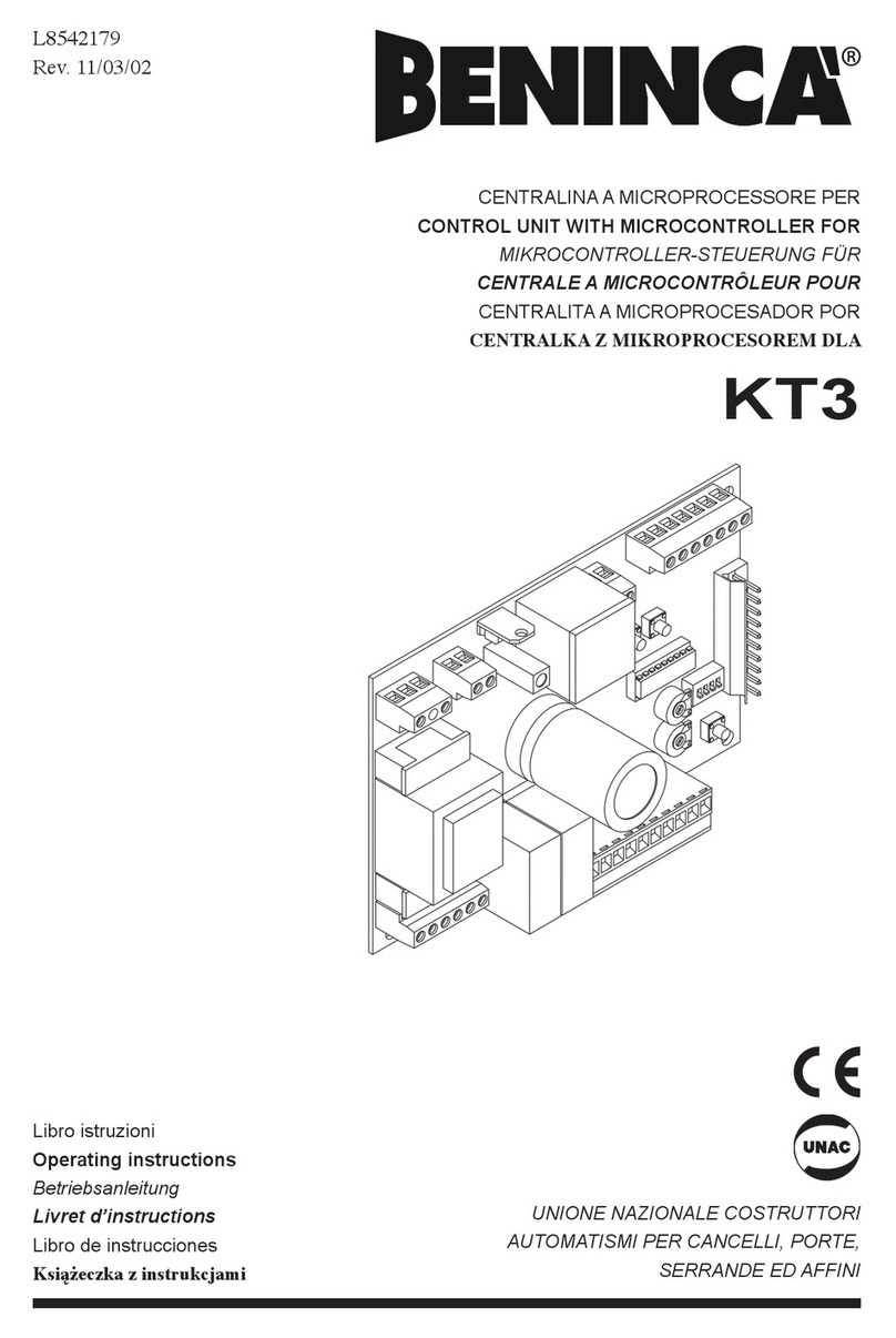
L8542181
Rev. 10/03/00
KTE
CENTRALINA A MICROPROCESSORE PER
CONTROL UNIT WITH MICROCONTROLLER FOR
MIKROCONTROLLER-STEUERUNG FÜR
CENTRALE A MICROCONTRÔLEUR POUR
CENTRALITA A MICROPROCESADOR POR
CENTRALKA Z MIKROPROCESOREM DLA
Libro istruzioni
Operating instructions
Betriebsanleitung
Livret d’instructions
Libro de instrucciones
Książeczka z instrukcjami
UNIONE NAZIONALE COSTRUTTORI
AUTOMATISMI PER CANCELLI, PORTE,
SERRANDE ED AFFINI
2
Dichiarazione CE di conformità Déclaration CE de conformité
EC declaration of confirmity Declaracion CE de conformidad
EG-Konformitatserklarung Deklaracja UE o zgodności
Con la presente dichiariamo che il nostro prodotto
We hereby declare that our product
Hiermit erklaren wir, dass unser Produkt
Nous déclarons par la présente que notre produit
Por la presente declaramos que nuestro producto
Niniejszym oświadczamy że nasz produkt
KTE
è conforme alle seguenti disposizioni pertinenti:
complies with the following relevant provisions:
folgenden einschlagigen Bestimmungen entspricht:
correspond aux dispositions pertinentes suivantes:
satisface las disposiciones pertinentes siguientes:
zgodny jest z poniżej wyszczególnionymi rozporządzeniami:
Direttiva sulla compatibilità elettromagnetica (89/336/
CCE, 93/68/CEE)
EMC guidelines (89/336/EEC, 93/68/EEC)
EMV-Richtlinie (89/336/EWG, 93/68/EWG)
Directive EMV (89/336/CCE, 93/68/CEE) (Compatibilité
électromagnétique)
Reglamento de compatibilidad electromagnética (89/336/
MCE, 93/68/MCE)
Norme armonizzate applicate in particolare:
Applied harmonized standards, in particular:
Angewendete harmonisierte Normen, insbesondere:
Normes harmonisée utilisées, notamment:
Normas armonizadas utilzadas particularmente:
EN 55022, EN 61000-3-2, EN 61000-3-3, EN 50082-1
Data/Firma
Direttiva sulla bassa tensione (73/23/CEE, 93/68/CEE)
Low voltage guidelines (73/23/EEC, 93/68/EEC)
Tiefe Spannung Richtlinie (73/23/EWG, 93/68/EWG)
Directive bas voltage (73/23/CEE, 93/68/CEE)
Reglamento de bajo Voltaje (73/23/MCE, 93/68/MCE)
Norme armonizzate applicate in particolare:
Applied harmonized standards, in particular:
Angewendete harmonisierte Normen, insbesondere:
Normes harmonisée utilisées, notamment:
Normas armonizadas utilzadas particularmente:
EN 60204-1, EN 60335-1
Data/Firma
Automatismi Benincà Srl
Via Capitello, 45
36066 Sandrigo (VI)
ITALIA
3
PGM P.P.
12345678910
13 14 15
1617181920
R4
Z2
C11
R9
R5
Q1
D4
D2
C1 D3
C3
Z6
R23
C2
R18 R16
U4
C19
D7
C18
C4
C5
C7 R26
R17 U1 B.E.
KTE
V1.1
C6
K4
D6
F1
F1 1A
C10
Z3
R8
R3
C8
Z5
C14
C13
RX1
J3
Z4
R2
R1
R7
C9
R6
R15
Q2
R21
U3
C16
D5
R22
C15
R14
R13
R12
R11
R20
R19
R32
R28
R30
R29
R31
C17
D1 DV1
R27
DV3
K2 K1
K3
R24
C12
Z1
R10
FUSE
6
KTE Control unit with microcontroller
Installation instructions.
a) The electrical installation and the operating logic must comply with the regulations in force.
b) It is advisable to keep the power cables (motor, power supply) separate from the command cables
(buttons, photocells, radio). To avoid interference it is preferable to provide and use two separate
sheaths.
c) Check all the connections again before supplying voltage.
d) A jumper must be fitted on any normally closed contacts that are not used.
e) If the direction of rotation of the motor is inverted, it is sufficient to invert the motor power supply
leads.
Input/Output functions
(1) Antenna input
(2) Antenna earth
(3) P.P. input= Step-by-Step input. Connected in parallel to the radio control output. Contact N.O.
(4) FTC input= Contact N.C. The opening of this contact during the closing manoeuvre causes inver-
sion of the stroke.
(5) STOP input= Contact N.C.
(6) +V output= Common output for all inputs.
(7,8) Blinking light= Blinking light supply output 24Vac (3W).
(9,10) Out 24Vac= Auxiliary supply output 24Vac (500mA max.).
(13) Transformer= 0V.
(14) Transformer= Voltage of the Soft-Start and of slowing Closing.
(15) Transformer= Motor speed.
(16,17) Motor output= To motor.
(18) Common Limit stop.
(19) FCC input= Contact N.C.
(20) FCA input= Contact N.C.
If a mechanical edge is fitted, connect the contact in SERIES to the contact of the photocell to have inver-
sion or in SERIES to the STOP button to have the STOP function.
The control unit is provided with a built-in radio module to receive remote controls both with a fixed code
and with a variable code at the frequency of 433.92MHz.
In order to use a remote control it must first be learnt; the memorising procedure is illustrated below. The
device is able to store up to 14 different codes.
The maximum work time of the control unit is 90 seconds. After having performed 4 complete manoeu-
vres (the term complete manoeuvre means starting from FC and arriving at the other FC), the control unit
memorises the mean work time and slows down the movement during closing. The time of the courtesy
light is 120 seconds.
On the supply transformer there is a faston connector which allows the motor power to be regulated at 3
different levels. Position the faston on the desired power.
It is possible to carry out a test on the control unit to check operation of the photocells; if you want to
use this function you have to supply power to at least the transmitters of the photocells (if you like, for
convenience’s sake, you can also supply power to the receivers) from the terminals of the blinking light
(terminals 7 and 8) and set the function as explained below in the paragraph SETTING THE PHOTOCELL
TEST. Once the test has been set up, before each closure the control unit checks the operation of the FTCs;
if they are faulty or occupied, after having given a signal for 3 seconds with the blinking light, the automatic
mechanism does not perform the manoeuvre. If the FTC is occupied after the TCA (Automatic closing time)
has elapsed, the automatic mechanism waits again for the whole set TCA.
Programming of the control unit
After having carried out any of the following programming operations, 4 complete manoeuvres must be
performed before you can again see slowing down during closure (starting from one limit stop and arriv-
ing at the other limit stop).
Cancelling the remote controls from the memory
To cancel the remote controls from the memory, supply power to the control unit holding down the pro-
gramming button PGM; the led will light up for about 5 seconds. When it goes out, the memory has been
cancelled.
7
Memorising a new remote control
Press the programming button PGM, the led will light up with a fixed light. Within 10 seconds, press the
button of the new remote control that you want to memorise. If the led does not remain lit with a fixed light
but starts blinking for 5s after you have pressed the PGM button, this means that the memory is full and
cannot store any more codes.
Setting the automatic closing time (TCA)
Press the programming button PGM twice, the blinking led will start to blink rapidly. The courtesy light will
blink every second until the PGM button is pressed again; if the number of blinks is less than 5, automatic
closure is disabled, whereas if it is larger than 5 the TCA is set at a number of seconds corresponding to
the number of blinks made by the courtesy light (up to a maximum of 255).
After 255 blinks, if the PGM button is not pressed the control unit automatically leaves the programming
procedure, disabling automatic closure.
Setting the threshold of intervention of the current limiter
The current limiter has 6 thresholds of sensitivity. To set the desired sensitivity, press the programming
button PGM a first time, then press the PP button; holding down the PP button, press the PGM button again
and the blinking led will go out. The courtesy light will blink every second until the PGM button is pressed
again. The set threshold of sensitivity decreases with the number of blinks made by the courtesy light:
after 1 blink there is the greatest sensitivity (that is the minimum power), after 6 blinks, if the PGM button
is not pressed again the control unit automatically leaves the programming procedure, memorising the
minimum sensitivity (that is the maximum power).
If the threshold of intervention of the current sensor is exceeded in opening, the motor stops. In closing,
if the threshold of intervention of the current sensor is exceeded the motor inverts the direction of move-
ment for 2 sec., then stops.
Setting the photocell test
Whenever this procedure is tested the setting of the photocell test varies (that is if previously the test was
switched off it is switched on, if previously the test was switched on it is switched off). To vary the setting
of the photocell test, press the programming button PGM a first time, then press the PP button (press and
release); press the PGM button again. The blinking led lights up with a fixed light, then the courtesy light
indicates the new setting of the test: 1 blink if the test is activated, 2 blinks if the test is deactivated.
AUTOMATISMI BENINCÀ Srl - Via Capitello, 45 - 36066 Sandrigo (VI) - Tel. 0444 751030 r.a. - Fax 0444 759728

Other Beninca Control Unit manuals

Beninca HEAD User manual

Beninca

Beninca HEAD User manual

Beninca BRAIN 24 User manual

Beninca

Beninca BRAIN 24 User manual

Beninca HEADY 24 3B User manual

Beninca

Beninca HEADY 24 3B User manual

Beninca BRAIN User manual

Beninca

Beninca BRAIN User manual

Beninca CORE User manual

Beninca

Beninca CORE User manual

Beninca CP.K3-RE User manual

Beninca

Beninca CP.K3-RE User manual

Beninca DA.C15 User manual

Beninca

Beninca DA.C15 User manual

Beninca LOGICA User manual

Beninca

Beninca LOGICA User manual

Beninca CP.ZED230-E User manual

Beninca

Beninca CP.ZED230-E User manual

Beninca CP.BULL OMI User manual

Beninca

Beninca CP.BULL OMI User manual

Beninca CP.B24ESA User manual

Beninca

Beninca CP.B24ESA User manual

Beninca Logica 230 User manual

Beninca

Beninca Logica 230 User manual

Beninca CP.M24-RE User manual

Beninca

Beninca CP.M24-RE User manual

Beninca DA.SO4 User manual

Beninca

Beninca DA.SO4 User manual

Beninca CP.MBE24 User manual

Beninca

Beninca CP.MBE24 User manual

Beninca DA.2XS433 User manual

Beninca

Beninca DA.2XS433 User manual

Beninca CP.B24-SW User manual

Beninca

Beninca CP.B24-SW User manual

Beninca DA.SO4 User manual

Beninca

Beninca DA.SO4 User manual

Beninca KER User manual

Beninca

Beninca KER User manual

Beninca START-I User manual

Beninca

Beninca START-I User manual

Beninca CP.J4 ESA User manual

Beninca

Beninca CP.J4 ESA User manual

Beninca CELL.P User manual

Beninca

Beninca CELL.P User manual

Beninca DA.24A User manual

Beninca

Beninca DA.24A User manual

Beninca RI.624 User manual

Beninca

Beninca RI.624 User manual

Popular Control Unit manuals by other brands

GESTRA CW 44 installation instructions

GESTRA

GESTRA CW 44 installation instructions

Elko iNels RFATV-2 quick start guide

Elko

Elko iNels RFATV-2 quick start guide

Honeywell TR80UWD Installation and operating guide

Honeywell

Honeywell TR80UWD Installation and operating guide

TE Connectivity FlexWave Prism installation guide

TE Connectivity

TE Connectivity FlexWave Prism installation guide

Pentair Fleck 2510 ECONOMINDER Service manual

Pentair

Pentair Fleck 2510 ECONOMINDER Service manual

Lunos 5/UNI-FT installation manual

Lunos

Lunos 5/UNI-FT installation manual

Canford 58-321 Technical data sheet

Canford

Canford 58-321 Technical data sheet

getAir SmartFan TOUCH Installation and operating instructions

getAir

getAir SmartFan TOUCH Installation and operating instructions

ADEMCO VISTAKEY Installation and setup guide

ADEMCO

ADEMCO VISTAKEY Installation and setup guide

Sensus AMR-960 installation instructions

Sensus

Sensus AMR-960 installation instructions

Control Technology Inc. CTI 2559-TC Installation and operation guide

Control Technology Inc.

Control Technology Inc. CTI 2559-TC Installation and operation guide

Pfeiffer TC 110 operating instructions

Pfeiffer

Pfeiffer TC 110 operating instructions

ETAS ES581.4 user guide

ETAS

ETAS ES581.4 user guide

Texas Instruments SimpleLink Wi-Fi CC3 20 Series user guide

Texas Instruments

Texas Instruments SimpleLink Wi-Fi CC3 20 Series user guide

LeakSmart PRO Installation and operation manual

LeakSmart

LeakSmart PRO Installation and operation manual

Espressif PAN100 manual

Espressif

Espressif PAN100 manual

PVA FCM100 Operation manual

PVA

PVA FCM100 Operation manual

NextLight Pro Series user manual

NextLight

NextLight Pro Series user manual

manuals.online logo
manuals.online logoBrands
  • About & Mission
  • Contact us
  • Privacy Policy
  • Terms and Conditions

Copyright 2025 Manuals.Online. All Rights Reserved.