ELNA Elnita ec 30 User manual

SERVICE MANUAL
MODEL: ec 30
First Edition: 25 June 2020

Contents
WHAT TO DO WHEN........................................................................................................................ 1 - 3
CHANGING EXTERNAL PARTS
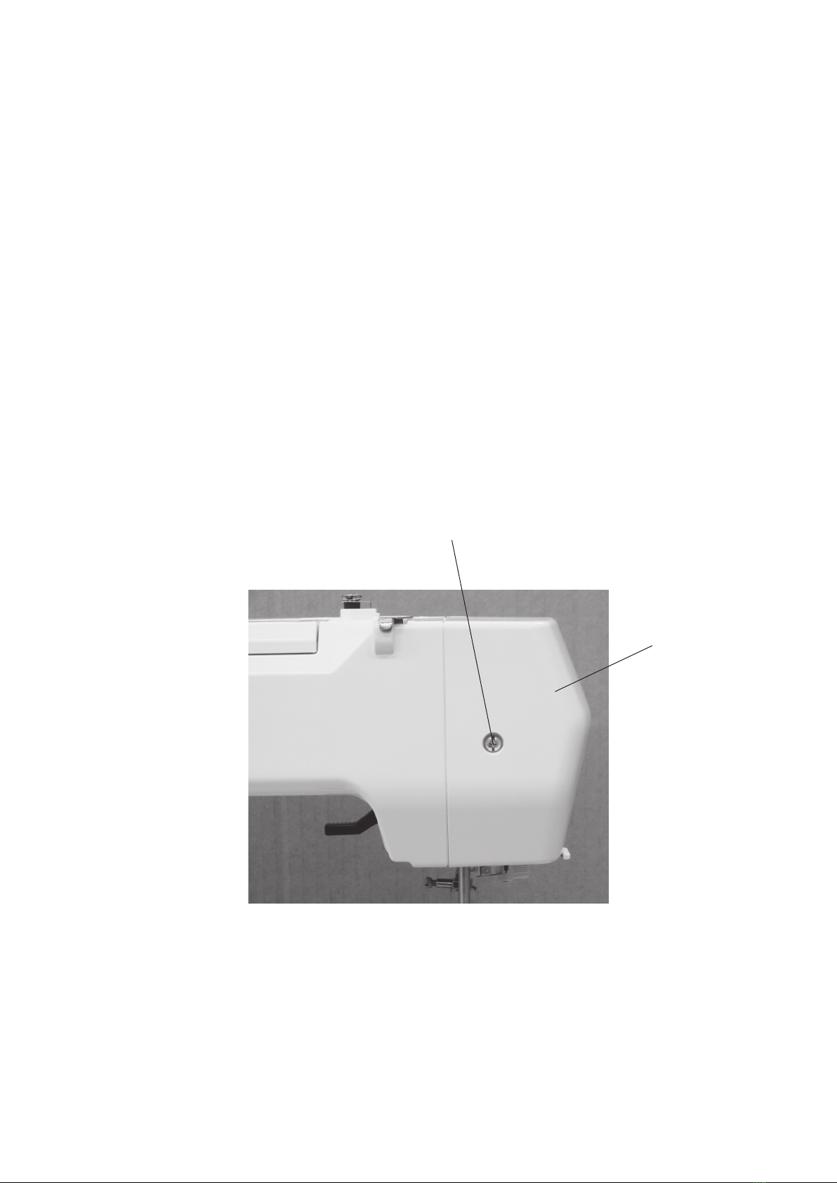
FACE COVER .........................................................................................................................................4
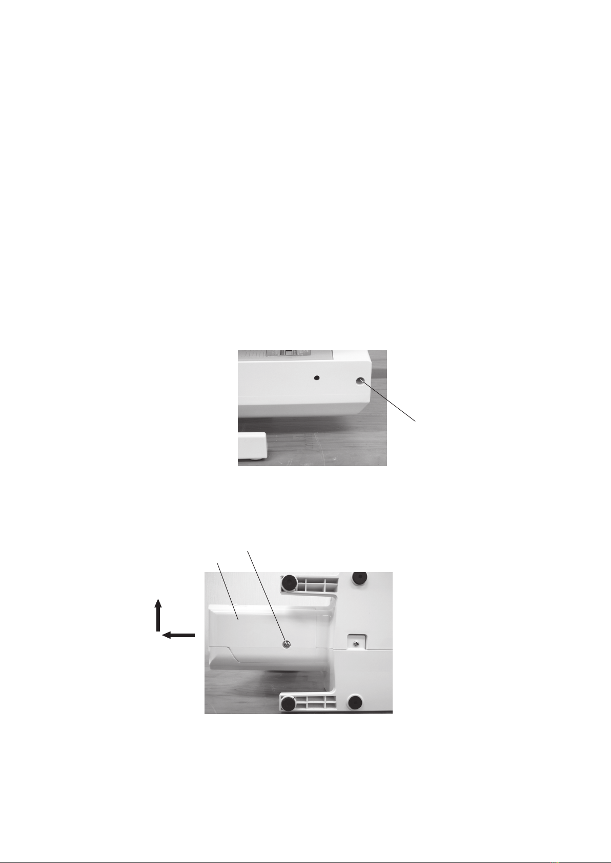
BED COVER ...........................................................................................................................................5
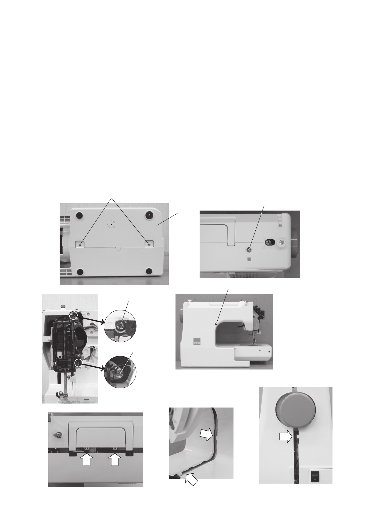
FRONT COVER ......................................................................................................................................6
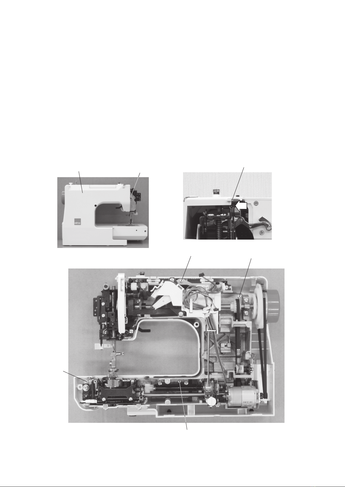
REAR COVER.........................................................................................................................................7
MECHANICAL ADJUSTMENT
PRESSER BAR HEIGHT ........................................................................................................................8
NEEDLE DROP POSITION.....................................................................................................................9
ADJUSTMENT OF HOOK TIMING .......................................................................................................10
ADJUSTMENT OF NEEDLE BAR HEIGHT..........................................................................................11
CLEARANCE BETWEEN NEEDLE AND TIP OF THE ROTARY HOOK ..............................................12
FEED DOG HEIGHT .............................................................................................................................13
BACKLASH BETWEEN HOOK GEAR AND LOWER SHAFT GEAR ...................................................14
TOP TENSION ......................................................................................................................................15
STRETCH STITCH FEED BALANCE ...................................................................................................16
REPLACEMENT AND ADJUSTMENT OF THE NEEDLE THREADER PLATE....................................17
SELF-DIAGNOSTIC TEST
SELF-DIAGNOSTIC TEST.............................................................................................................. 18-22
TO DISPLAY THE VERSION OF THE PROGRAM...............................................................................22
REPLACING THE ELECTRONIC COMPONENTS
PRINTED CIRCUIT BOARD A CONNECTION .....................................................................................23
PRINTED CIRCUIT BOARD A ..............................................................................................................24
PRINTED CIRCUIT BOARD L...............................................................................................................25
DRIVING MOTOR (DC MOTOR) ..........................................................................................................36
SWITCHING REGULATOR UNIT..........................................................................................................27
PARTS LIST.................................................................................................................................... 28-41

1
Condition Cause Howtox Reference
1. Skipping
Stitches
1. Needleisnotinsertedproperly.
2. Needleisbentorworn.
3. Incorrectlythreaded.
4. Needleorthreadare
inappropriateforthefabric
being sewn.
5. Sewingonstretchfabric.
6. Inappropriateneedlebar
height.
7. Inappropriateneedletohook
timing.
8. Inappropriateneedletohook
clearance.
Inserttheneedleproperly.
Changetheneedle.
Rethread.
Usetherecommendedsewingneedle
andthethread.
UseaHAx1#11bluetipneedle.
Seemechanicaladjustment“Adjustment
ofNeedlebarheight”.
Seemechanicaladjustment“Adjustment
ofHooktiming”.
Seemechanicaladjustment“Clearance
betweenneedleandtipoftherotary
hook”.
P. 11
P. 10
P. 12
2. Fabricisnot
moving
1. Incorrectfeeddogheight.
2. Feeddogisinthedownposition.
3. Threadonthebottomsideof
thefabricisjammedup.
4.Feeddogteethareworn.
Seemechanicaladjustment“Feeddog
height”.
Raisethefeeddog.
Makesuretobringbothneedleand
bobbinthreadsunderthefootwhenstart
sewing.
Changethefeeddog.
P. 13
WHAT TO DO WHEN

2
Condition Cause How to Fix Reference
3. Breaking
upper
thread.
1. Initial sewing speed is
toofast.
2. Threadpathisincorrect.
3. Needleisbentordull.
4. Toptensionistoostrong.
5. Needlesizeisinappropriatefor
fabric.
6. Needleeyeisworn.
7. Needleholeinneedle plate is
wornorburred.
Startwithmediumspeed.
Usetheproperthreadpath.
Replacewithanewneedle.
Adjusttoptensioncorrectly.
Useappropriateneedleforfabricand
threadinuse.
Changetheneedle.
Repairtheholeorreplacetheneedle
plate.
4. Breaking
bobbin
thread.
1.Bobbinholderisincorrectly
threaded.
2.Toomuchthreadiswound
onthebobbin.
3.Lintisstuckinsidethebobbin
holder.
4.Threadqualityistoolow.
5.Threadisjammingaroundthe
bobbinholder.
Setthebobbinthreadcorrectly.
Adjustthepositionofbobbinwinder
stopper.
Cleanthebobbinholder.
Changetoahighqualitysewingthread.
Clearoutthejammingthread.
5. Needle
breaks
1.Needleishittingtheneedleplate.
2.Needleisbentorworn.
3.Needleishittingthehook.
4.Fabricisbeingpulledtoostrongly
whilesewing.
Seemechanicaladjustment“Needledrop
position”.
Changetheneedle.
Seemechanicaladjustment“Clearance
betweenneedleandtipoftherotary
hook”.
Guidethefabricgentlywhilesewing.
P. 9
P. 12
WHAT TO DO WHEN

3
Condition Cause Howtox Reference
6.Noisy
operation
1. Backlashbetweenhookgear
andlowershaftgearistoo
great.
2. Lowershaftgearisloose.
3.Inappropriatebelttension.
4. Notenoughoil.
5.Uppershaftgearisloose.
Eliminatethebacklash.
Eliminatethelooseness.
Seepartremovalandreplacement
“Drivingmotor(DCmotor)”.
Oilallmovingparts.
Eliminatethelooseness.
P. 14
P. 14
P. 26
7.Deformation
pattern
1.Inappropriatefeedbalance.
2. Toptensionistoostrong.
Adjustthefeedbalancingscrew.
Seemechanicaladjustment
“Toptension”.
P. 16
P. 15
WHAT TO DO WHEN

4
CHANGING EXTERNAL PARTS
FACE COVER
To remove:
1.Removethesetscrewq.
2.Removethefacecoverw.
To attach:
3.Followtheaboveprocedureinreverse.
w
q

5
BED COVER
To remove:
1.Removethesetscrewq.
2.Removethesetscreww.
3.Movethebedcoveretothelefttounlockthecover.
4.Slidethebedcovertotheuptoremovethecover.
To attach:
5.Followtheaboveproceduresinreverse.
CHANGING EXTERNAL PARTS
q
w
e

6
CHANGING EXTERNAL PARTS
FRONT COVER
To remove:
1.Removethefacecoverandbedcover(Refertopages4and5).
2.Removethesetscrewsq(2pcs.).
3.Loosenthesetscreww.
4.Loosenthesetscrewe.
5.Loosenthesetscrewr.
6.Removethesetscrewt.
7. Disengagethefrontcoverandrearcoverhooks.
8.Removethefrontcover y.
9.DisconnectalltheconnectorsfromthecircuitboardA.
NOTE:
Donotdisconnecttheconnectorsbypullingcords.Todisconnect,grasptheconnector,notthecord.
To attach:
9.Followtheaboveproceduresinreverse.See"PRINTEDCIRCUITBOARDACONNECTION"(Page23).
q
w
t
e
r
y

7
CHANGING EXTERNAL PARTS
REAR COVER
To remove:
1.Removethefacecover,bedcoverandfrontcover(Refertopages4to6).
2.Removethesetscrewq.
3.Removethesetscrewsw(4pcs.).
4.Removetherearcover e.
5.Disengagetherearcover eandthreadtensionhooks r.
To attach:
6.Followtheaboveproceduresinreverse.
qr
e
ww
w
w

8
6.0 mm
MECHANICAL ADJUSTMENT
PRESSER BAR HEIGHT
Thedistancebetweenthebottomofthepresserfootinuppositionandtheneedleplateshouldbe6.0mm.
1. Removethefaceplateandneedle.
2. Lowerthefeeddogbelowtheneedleplate.
Place6.0mmthickblockunderthe presserfootandlowerthepresserfootlifter.
3. Loosenthehexagonalsocketscrew.Raisethepresserfootlifterandtightenthesetscrewrmly.
Attachtheneedleandfaceplate.
NOTE:
Makesurethatthepresserfootshouldbeparalleltothefeeddogslotsintheneedleplate.
Feed dog slots
Zigzagfoot(A)
Feed dog
Block
Needle plate Presserfootshouldbeparallel
tothefeeddogslots.
Hexagonalsocketscrew Presserfootlifter

9
0.2 mm
ormore
0.2 mm
ormore
(A)
(B)
A = B
MECHANICAL ADJUSTMENT
NEEDLE DROP POSITION
Needleplatehole
Selectthezigzagstitch.
Setthestitchwidthto“5.0”.
Theclearancebetweentheneedledroppositionandtheedgeofneedleshouldbe0.2mmormoreforboth
sides.
Ifnot,maketheadjustmentasfollows:
1. Turnthepowerswitchon.
2. Removethefacecover(Refertopage4).
3. Setthestitchwidthto“5.0”.
4. Makethefollowingadjustmentsiftheclearancebetweentheneedledroppositionandtheadgeoftheneedle
areevenforbothsides.
* Turnthesetscrewclockwise(inthedirectionofA)iftheclearanceontherightsideoftheneedleplateholeis
smallerthan0.2mm.
* Turnthesetscrewcounterclockwise(inthedirectionofB)iftheclearanceontheleftsideoftheneedleplate
holeissmallerthan0.2mm.
NOTE:
Checkthehooktimingafterthisadjustment.
Setscrew

10
Selectthezigzagstitch .
Setthestitchwidthto“5.0”.
Theamountofascendingtraveloftheneedlebarfromitslowerpositiontothepositionwherethetipofthe
rotaryhookexactlymeetstherightsideoftheneedleshouldbe1.4to2.0mm.
1.Removethebedcover(Refertopage5).
2.Selectthezigzagstitch.
Setthestitchwidthto“5.0”.
Bringtheneedleatrightlowestneedleposition.
3.Removethesetscrewontheneedleplate,theneedleplateandthebobbinholder.
4.Loosenthehexagonalsocketscrewsonthelowershaftgear.
5.Turnthehandwheeltowardyoutoraisetheneedlebar1.7mmfromitsrightlowestposition.
6.Whileholdingthehandwheeltopreventtheneedlebarfrommoving,turnthelowershaftgearinthedirection
ofarrowuntilthetipoftherotaryhookexactlymeetstherightsideoftheneedle.
7. Tightenthehexagonalsocketscrewsonthelowershaftgear.
8.Attachthebobbinholder,needleplateandbedcover.
MECHANICAL ADJUSTMENT
ADJUSTMENT OF HOOK TIMING
Needle plate
Bobbinholder
Hexagonalsocketscrew
Lowershaftgear
Rightposition
Tipofhookmeetstherightsideoftheneedle
Lowest needle position
1.4 to 2.0 mm
Setscrew
Hexagonalsocketscrew

11
Thestandarddistancebetweentheupperedgeoftheneedleeyeandtheuppersurfaceofthehookrace
shouldbeintherangeof3.0to3.6mmwhenthehookpointmeetstherightsideoftheneedleinitsascending
travelfromrightlowestpositionofthemaximumwidthzigzagstitch.
1.Removethefacecoverandbedcover(Refertopages4to5).
2.Turnthepowerswitchon.
Selectthezigzagstitch,andsetthestitchwidthto“5.0”.
Bringtheneedletotherightlowestposition.
3.Removethesetscrewontheneedleplate,theneedleplateandthebobbinholder.
4.Turnthehandwheeltowardyouuntilthehookpointmeetstherightsideoftheneedle.
5.Loosenthehexagonalsocketscrewandmovetheneedlebarupordowntoadjusttheneedleheight.
6.Tightenthehexagonalsocketscrew.
7. Attachthebobbinholder,needleplateandfacecoverandbedcover.
NOTE:
Beforeperformingthisadjustment,checktheneedletohooktiming.
MECHANICAL ADJUSTMENT
ADJUSTMENT OF NEEDLE BAR HEIGHT
3.0 to 3.6 mm
Upperedgeofneedleeye
Hookrace(unit)
Uppersurfaceofhookrace
Tipofhookmeetstherightsideoftheneedle
Rightposition
Needle plate
Bobbinholder
Setscrew
Hexagonalsocketscrew

12
Adjustment procedure:
1.Removethefacecover.(Refertopage4).
2.Removetheneedleplateandbobbinholder.
Attachthemasterneedle.
Turnthepowerswitchon.
Selectthezigzagstitch,andsetthestitchwidthto“5.0”.
3.Removethesetscrewontheneedleplate,theneedleplateandthebobbinholder.
Replacetheneedlewiththemasterneedleandtightentheneedleclampscrew.
4.LoosenthesetscrewsA(2pcs.)andmovethepresserbarbaseplateinthedirectionofthearrows(BorC).
*MovethepresserbarbaseplateinthedirectionofBwhentheclearanceistoolarge.
*MovethepresserbarbaseplateinthedirectionofCwhentheclearanceittoosmall.
Adjusttheclearancebetweeentheneedleandhookbetweeen-0.10to+0.05mm.Tightenthesetscrews.
*Theedgeofpresserbarbaseplateshouldalwaystouchesthebosseswhileadjustingtheclearanceit.
5.Attachthebobbinholderandneedleplate.Attachthefacecover.
NOTE:
Besurethattheclearancebetweentheneedledroppositionandtheedgeofneedleshouldbe0.2mmmore
forbothsides(Refertopage9).
*Theclearancebetweentheneedleandthepointofhookshouldbe–0.10to+0.05mm.
CLEARANCE BETWEEN NEEDLE AND TIP OF THE ROTARY HOOK
MECHANICAL ADJUSTMENT
Boss
Needle plate
Setscrew
SetscrewA
DirectionB
DirectionC
Bobbinholder
Needleclampscrew
–0.10to+0.05mm
Tipofhook
Masterneedle

13
Thehighestpositionofthefeeddogshouldbe0.80to0.95mmfromthesurfaceoftheneedleplate.
To check:
1.Lowerthepresserfoot.
2.Turnthehandwheeltowardyoutoraisethefeeddogatitshighestposition.
Thedistancebetweenthefeeddogandtheuppersurfaceoftheneedleplateshouldbe0.80to0.95mm.
Ifitisnotintherange,adjustasfollows.
To adjust:
3.LoosenthescrewA.
4.Turnthehandwheeltobringthefeeddogtoitshighestposition.
5.Ifthefeeddogheightislowerthan0.80mm:turnadjustingscrewBinthedirectionofC.
6.Ifthefeeddogheightisheigherthan0.95mm:turntheadjustingscrewBinthedirectionofD.
7. TightenthescrewA
FEED DOG HEIGHT
MECHANICAL ADJUSTMENT
0.80 to 0.95 mm
Uppersurfaceoftheneedleplate
A
B
DC

14
Therotaryplayofthehookpointshouldbe0.8mmorlesswhenitisinbetweenthespanofthefeeddogteeth,
andthegearsshouldturnsmoothly.
1.Removetheneedleplateandbobbinholder.
2.Removethebedcover(Refertopage5).
3.LoosenthesetscrewA.
*Iftherotaryplayistoolarge,turnthelowershaftbussinginthedirectionofB.
*Iftherotaryplayistoosmall,turnthelowershaftbussinginthedirectionofC.
4.TightenthesetscrewA.
5.Attachthefrontcover.
6.Attachthebobbinholderandneedleplate.
BACKLASH BETWEEN HOOK GEAR AND LOWER SHAFT GEAR
MECHANICAL ADJUSTMENT
B
C
Needle plate
Spanoffeeddogs
Hook point
0.8mmorless
SetscrewA
Notch
Lowershaftbushing
Setscrew
Bobbinholder

15
MECHANICAL ADJUSTMENT
TOP TENSION
Thetoptensionshouldbebetween75to90gfwhenpullingthethread(polyestersewingthread#50(white))up
inthedirectionofarrow(Makesurethethefootislowered)withthetensiondialat“4”.
Ifthetensionisoutoftherange,adjustasfollows:
1.Removethefrontcover(Refertopage6).
2.Setthetensiondialat“4”.
3.Afterthreadingtheupperthread,lowerthepresserfoot.
•Ifthetoptensionistootight,turntheleadscrewinthedirectionA.
•Ifthetoptensionistooloose,turntheleadscrewinthedirectionB.
4.Checkthetoptensionandattachthefrontcover.
Polyestersewingthread#50(white)
Pullthethreadatthespeedof110mm/secinthedirectionofarrow.

16
MECHANICAL ADJUSTMENT
STRETCH STITCH FEED BALANCE
To check:
1. Turnthepowerswitchon.
Besurethefeedbalancingdialissetatstandardpositionasshownbelow.
2. Selectthetriplestitch“”(stitchpattern#05).
3. Sewthe15piecesoftriplestitchasshownbelow.
Besurethatthetotalstitchlengthfromthe3rdpieceto13thpieceiswithintherangeof25to27mm.
Ifnot,adjustasfollows;
To adjust:
4.Removethecap.
•Turnthehexagonalsocketscrewinthedirectionof(A)ifthetotallengthof10piecesofthetriplestitch
patternisshorterthan25mm.
•Turnthehexagonalsocketscrewinthedirectionof(B)ifthetotallengthof10piecesofthetriplestitch
patternislongerthan27mm.
5.Sewthetriplestitch15piecesagainaftertheadujsutment.
Besurethatthetotalstitchlengthfromthe3rdpieceto13thpieceiswithintherangeof25to27mm.
Attachthecap.
Feedbalancingdial
(Standardposition)
Hexagonalsocketscrew
Cap
(A)(B)
Turnthepowerswitchon. TheLEDdisplaywill
indicate“01”.
Pressthestitchlength
adjustingkey
4 times to
displaythe“05”.
Pressthe
start/stop
button
.
Feedlaguratorplate
Sewthetriplestitch15piecesagainafter
theadujsutment.
25 to 27 mm

17
X
Threaderplatesupporter
Setscrew
Threader
positioning
plate
FIG. 3
Pin
Adjustmentofleftorrightdirection
Threaderplate
Hexagonalsocketscrew
Nut
Viewfrom"X"
Verticaladjustment
FIG. 2
FIG. 1
REPLACEMENT AND ADJUSTMENT OF THE NEEDLE THREADER PLATE
Ifthehookofthethreaderplateisdamaged,changeandadjustthepartasfollows:
TO CHANGE THE THREADER PLATE:
1. Pushdowntheneedlethreaderknobandpullthethreaderplatesupporterdowntoremoveit(seeFIG1).
2. Toinstalltheneedlethreaderplate,linethegrooveupwiththepinandpushituptosnapt.
TO ADJUST THE THREADER PLATE POSITION:
3. If the hook on the threader positioning plate touches the top or bottom side of the needle hole, loosen
hexagonalsocketscrewandadjustthehookposition(FIG.2).
4. Ifthehookonthethreaderplatetouchestheleftorrightsideoftheneedlehole,loosensetscrewandadjust
thehookposition(FIG3).
Replacingthethreaderplatesupporter
(withthethreaderplateattached)
MECHANICAL ADJUSTMENT

18
TO ENTER SELF-DIAGNOSTIC MODE:
Preparation:
1.Turnthepowerswitchoff.
2.Movethebobbinwinderspindletotheleft.
3.Raisethefeeddog.
4.Setthespeedcontrollevertotheleft.
5.Removethepresserfootandraisethepresserfootlifter.
6.Turnthehandwheeltowardyoutoraisetheneedletoitshighestposition.
NOTE:
•Becareful:thesewingmachinemaystartrunninginitsownwhileintestmode.
•Turnoffthepowerswitchbeforereplacinganyparts.
•Repeatthediagnostictestuntiltheproblemhasbeenresolved.
To begin:
Turnontheswitch.Ifanyofthefollowingproblemsoccur,taketherecommendedactionsintheorderthey
areshown.
1.Themachinedoesnotrespondwhenthepowerswitchisturnedon:
•Checkeachconnectorconnection.
•Replacetheswitchingregulator(withthemachinesocket).
•ReplacetheprintedcircuitboardA.
2.Thesewingmachinelampdoesnotlightup:
•BesureallconnectorsareconnectedtothecircuitboardLandAproperly(Refertopage23).
•ReplacetheprintedcircuitboardL.
•ReplacetheprintedcircuitboardA.
SELF-DIAGNOSTIC TEST
1. Turnthepowerswitchonwhile
simultaneouslypressingauto-lock
buttonandneedleup/downbutton.
2. TheLEDdisplay
willindicate“ 1”.
3. Pressthe
MODEkey
to
enterthe
self-diagnosticmode.
Table of contents
Other ELNA Sewing Machine manuals

ELNA
ELNA 2100 - LEAFLET User manual

ELNA
ELNA eXperience 620 User manual

ELNA
ELNA eXperience 660 User manual

ELNA
ELNA EXPRESSIVE 820 User manual

ELNA
ELNA eXcellence 760 PRO User manual

ELNA
ELNA 945 User manual

ELNA
ELNA 9500 - LEAFLET User manual

ELNA
ELNA eXperience 660 User manual

ELNA
ELNA 6003 - LEAFLET User manual

ELNA
ELNA eXpressive920 User manual