ELTEX VP-12P User manual

Username:admin
Password:password
IP phones
VP-12, VP-12P
Operation manual
Firmware version1.5.0

VP-12, VP-12P IP phones. Operation manual
2
Table of content
1 Device description .............................................................................................................4
1.1 Intended use............................................................................................................................... 4
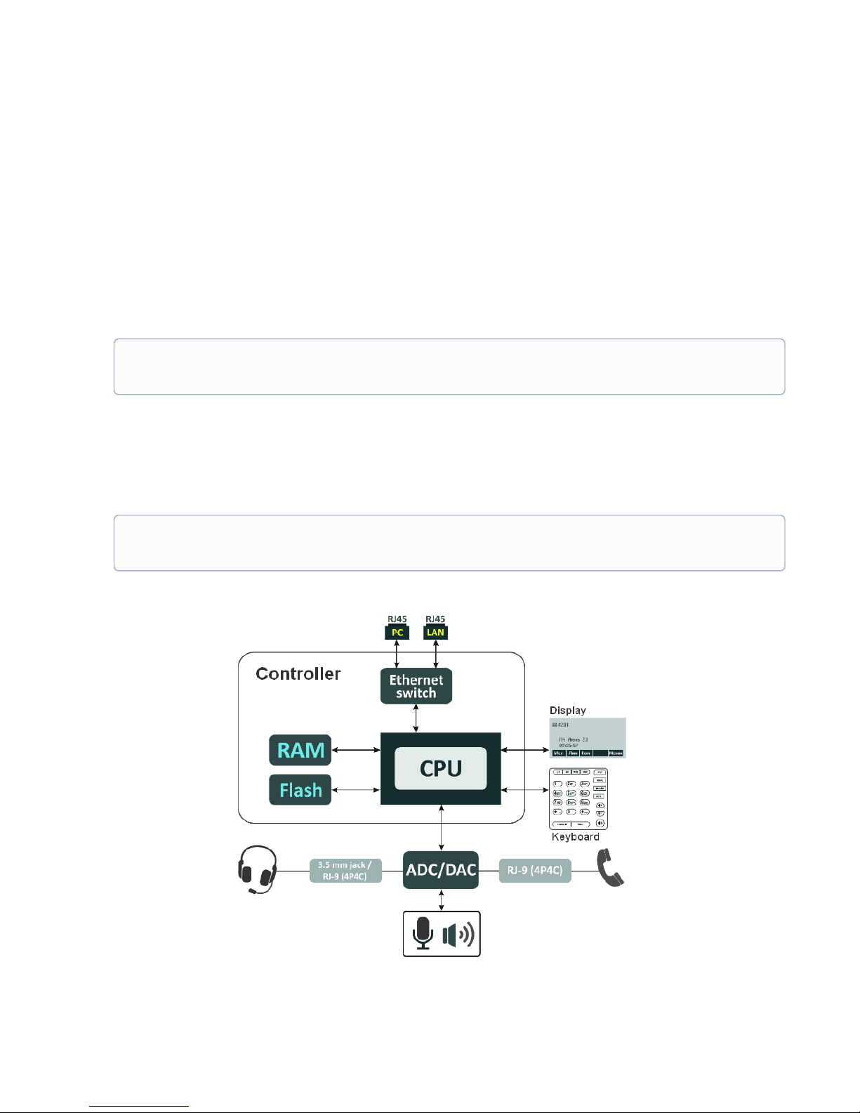
1.2 Device design and Operating principle ..................................................................................... 5
1.3 Main specifications ................................................................................................................... 6
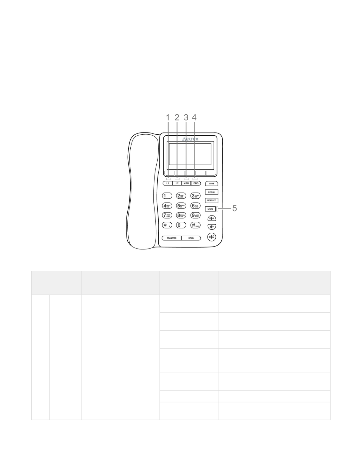
1.4 Design....................................................................................................................................... 10
1.5 Status indication on graphic display....................................................................................... 12
1.6 Delivery package...................................................................................................................... 13
2 Managing VP-12(P) via web interface ............................................................................14
2.1 Getting started ......................................................................................................................... 14
2.2 Configuring VP-12(P)............................................................................................................... 18
2.3 Monitoring VP-12(P) ................................................................................................................ 74
3 Example of device configuration ....................................................................................84
4 Appendices to VP-12(P) operation manual....................................................................89
4.1 Device automatic update algorithm based on DHCP ............................................................ 89
4.2 System recovery after firmware update failure...................................................................... 92
4.3 Running user-defined script upon system startup................................................................. 92
4.4 DHCP client configuration in multiservice mode................................................................... 94

VP-12, VP-12P IP phones. Operation manual
3
IP phones VP-12 and VP-12P(hereinafter the "device") are designed to provide VoIP services to the network
clients. The device is intended for operation in home or small office (SMB) environment.
This operation manual describes intended use, key specifications, configuration, monitoring, and firmware
update for VP-12(P) IP phones.

VP-12, VP-12P IP phones. Operation manual
4
1 Device description
•Intended use
•Device design and Operating principle
•Main specifications
•Design
•Top panel of the device. Light indication
•Rear panel of the device
•Status indication on graphic display
•Delivery package
1.1 Intended use
VP-12P – IP phone providing voice services and PC connection to IP network via only one cable. The device
supports PoE technology and has advanced functionality, high quality, and universal style.
VP-12P is designed for organizations with high requirements to transmitted voice data, stability and usability.
The figure below shows VP-12(P) connection diagram:
VP-12(P) connection diagram

VP-12, VP-12P IP phones. Operation manual
5
1.2 Device design and Operating principle
VP-12(P) IP phone includes the following subsystem:
•Controller featuring:
•Realtek RTL8972C highly-integrated System-on-a-Chip (SoC), including a CPU, 100 Mbits switch
with a built-in PHY, hardware L2/L3/L4 acceleration;
• flash-memory–16MВ;
• SDRAM –128MВ;
• codec(ADC/DAC);
•3.2 inch liquid crystal display with 128x64 px resolution;
•Realtek ALC5621 or Realtek ALC5633Q voice codec;
•Fully-featured digital keyboard with additional function keys;
•1 x LAN port: RJ-45 10/100BASE-T;
•1 x PC port: RJ-45 10/100BASE-T;
•1 x Handset port: RJ-9 (4P4C) for connecting a handset;
•1 x Headset: 3.5 mm jack or RJ-9 for connecting a headset;
Design diagram for device is depicted in the figure below.
Depending on hardware version: for versions below 2.0 — Realtek ALC5621 codec; for versions
2.0 and later — Realtek ALC5633Q codec.
Depending on hardware version: for versions below 2.0 — 3.5 mm jack; for versions 2.0 and later
—RJ-9 (4P4C).

VP-12, VP-12P IP phones. Operation manual
6
The device runs under Linux operating system. Basic control functions are performed by Realtek processor
which enables IP packet routing, VoIP operation, etc.
1.3 Main specifications
General parameters
Power supply •power adapter 5V DC, 2 А
•PoE support (IEEE 802.3af), class 2
Power consumption up to 3.5 W (max. current consumption is0.7 А)
Operating temperature range from +5 to +40°C
Relative humidity at 25°Сno more than 80%
Dimensions 223x178x89,5 mm
Weight up to 0.52 kg
Interfaces •LAN: 1 port of Ethernet RJ-45 10/100BASE-T
•PC: 1 port of Ethernet RJ-45 10/100BASE-T
•Handset: 1 RJ-45 (4P4C) port for connecting a handset
•Headset: 1 port for connecting a headset
Ethernet LAN interface specification
Number of ports 1
Electric port RJ-45
Data transmission rate •10 Mbps
•100 Mbps
•autonegotiation
Standard support BASE-T
Ethernet PC interface specification
Number of ports 1
Electric port RJ-45
Data transmission rate •10 Mbps
•100 Mbps
•autonegotiation
Standard support BASE-T

VP-12, VP-12P IP phones. Operation manual
7
Main features and capabilities
VoIP capabilities
Supported protocols •SIP
Quantity of accounts 2
Key features •2 SIP accounts configuring independently
•Support for up to 4 redundant SIP servers
•Flexible dialplan
•Operation without a SIP server
•Caller name and number displaying (CallerID)
•Mute
•Redial
•Different ring-tones for different accounts
•Call History
•Local phonebook for 200 phone numbers
•LDAP Remote Phonebook
•Speakerphone mode
•Operation behind NAT
•Short text messages transmitting and receiving (SIP MESSAGE)
Operation behind NAT •NAT keepalive
•STUN mode
•Public IP
Security •SIP over TLS
•SRTP
Voice features •Echo cancellation, G.165, G.168 (AEC) recommendations
•Voice activity detector (VAD)
•Comfort Noise Generation (CNG)
•DTMF signals detection and generation
DTMF signals detection and
generation
•Inband
•RFC2833
•SIP INFO
Codecs •G.711а
•G.711u
•G.723.1
•G.726
•G.729

VP-12, VP-12P IP phones. Operation manual
8
Value Added services •Call Hold
•Call Transfer
•Call Waiting;
•Call Forward on Busy
•Call Forward on No response
•Call Forward Unconditional
•Do not disturb (DND)
•Caller Line Identification Restriction –CLIR
•Hotline/Warmline
•3 Way-conference
•Stop dialing by pressing #
Network features
Key features •Opportunity to divide voip, managment and pc-data traffic to different
vlans
Protocols •Static IP
•DHCP
•PPPOE
Support for PPPoE •PAP, SPAP and CHAP authorization
•PPPoE compression
Support for DHCP option 1 - Subnet Mask
3 - Router
6 - Domain Name Server
12 - Host Name
15 - Domain Name
26 - Interface MTU
28 - Broadcast Address
33 - Static Route
42 - Network Time Protocol Servers
43 - Vendor-Specific Information
66 - TFTP ServerName
67 - Bootfile name
120 - SIP Servers
121 - Classless Static Route
249 - Private/Classless Static Route(Microsoft)
Support for QoS mechanisms •IP DSCP header
•802.1P
Support for DNS •Static DNS servers addresses
•Obtaining DNS servers addresses via DHCP
Support for NTP •Static NTP server address assignment
•Obtaining NTP server address via DHCP
Network access limitation •Firewall
•MAC filter

VP-12, VP-12P IP phones. Operation manual
9
Routing •Static routing
•Routing rules assignment via DHCP (Option 33, 121, 249)
Mangement and monitoring
Key features •Access limitation through network interfaces
•Flexible settings for access to display menu
•Bilingual
Interfaces •Web interface
•SSH
•Telnet
•TR-069
•Display menu
Debug information output •Syslog
•Telnet
•File
Loading/updating of software and
configuration •Autoupdate by schedule
•Periodical autoupdate
•Centralized software update through ACS server (TR-069)

VP-12, VP-12P IP phones. Operation manual
10
1.4 Design
VP-12(P) IP phone is enclosed into 223x178x89.5 mm plastic case.
1.4.1 Top panel of the device. Light indication
The figure below shows VP-12(P) top panel layout
VP-12(P) top panel is equipped with LED indicators:
Front panel
element
Description LED state Device state
1, 2 L1, L2 Status indicators of the first
and second lines
off The account is registered and is in waiting
mode of incoming/outgoing call
solid green The account is active and is in the
conversation/dial mode
flashes green
(in standby mode)
The account is in the registration process
flashes green
(during conversation)
The second incoming call, incoming call on
the second line, one or more calls are on
hold
flashes green (during
incoming call)
Incoming call
solid red Registration error
solid orange The account is in the DND (do not disturb)
mode

VP-12, VP-12P IP phones. Operation manual
11
Front panel
element
Description LED state Device state
3 MSG Voice message indicator off There are no unread messages
flashes red There are unread messages
4 DND Indicator of the DND service
status
flashes red DND mode is activated on at least one
account
off DND mode is not activated
5 MUTE Indicator of disabled mic solid red Mute mode is activated for the current
conversation
off Mute mote is not activated
1.4.2 Rear panel of the device
VP-12(P) rear panel layout depends on hardware version. Figure A shows the layout for versions below 2.0, Figure B
shows the layout for version 2.0 and later ones.
Figure А –VP-12(P) rear panel layout for hardware versions below 2.0
Figure B–VP-12(P) rear panel layout for hardware version 2.0 and later

VP-12, VP-12P IP phones. Operation manual
12
Rear panel layout Description
6 Headset Port for connecting a headset:
• for hardware versions below 2.0 – 3.5 mm port
• for version 2.0 and later – RJ-9 (4P4C) port
7 DC port for power adapter connection, 5V 2A
8 PC 10/100BASE-T Ethernet port (RJ-45 port) for connection to PC
9 LAN 10/100BASE-T Ethernet port (RJ-45 port) for connection to LAN
1.5 Status indication on graphic display
Indication status on graphic display
Number Description
1Indicator of voice interface:
– handset is off-hook;
– handset is on-hook;
– speakerphone is activated;
– headphones are activated.
2 Phone number of the current account
3 Current date and time
4 Actions taken upon pressing soft-keys

VP-12, VP-12P IP phones. Operation manual
13
1.6 Delivery package
VP-12(P) standard delivery package includes:
• Universal subscriber terminal(+handset and cable for handset connection);
•220/5V 2Аpower adapter;
•RJ-45 cable;
•Quick user manual and warranty certificate.
A headphones might be added to delivery package upon a request

VP-12, VP-12P IP phones. Operation manual
14
2 Managing VP-12(P) via web interface
2.1 Getting started
•Pre-starting procedures
•Web interface description
•Web interface operation modes
•Key elements of web interface
•Applying configuration
•Discarding changes
2.1.1 Pre-starting procedures
To start the operation, you should connect the device to PC via LAN interface. Use a web browser:
1. Open web browser, i.e Firefox,Opera,Chrome.
2. Enter the device IP address in the browser address bar.
When the device is successfully detected, username and password request page will be shown in the browser
window:
It is recommended to reset the device to factory settings when switching it on for the first time. Use
display menu and buttons to reset the device – implement the following:
Menu -> 3. Settings -> 2. System -> 5. Reset settings -> Yes
The device will automatically reload.
By default, IP phone receives an IP address and other network parameters via DHCP.
To get an obtainedIP address, implement Menu -> 1. Statususing display menu.

VP-12, VP-12P IP phones. Operation manual
15
3. Enter your username into 'Login' field and password into 'Password' field.
4. Click 'Log in' button. Monitoring panel will be shown in the browser.
2.1.2 Web interface description
2.1.2.1 Web interface operation modes
Web interface of the VP-12(P) device can operate in two modes:
•Configuration– a system mode which enables full device configuration. The mode has three tabs:
Network, VoIP and System.
•Monitoring– system monitoring mode–allows you to view various device operation information:
Internet connection activity, phone port status, amount of received/sent data via network interfaces, etc.
2.1.2.2 Key elements of web interface
User interface window is divided into 6 areas(see figure "Key elements of web interface"):
1. User name for log in, session termination button in the web interface ('Sign Out') for the current user
and dropped down menu for changing language.
2. Menu tabs allow you to select configuration and monitoring categories: Network, VoIP, System,
Monitoring.
3. Submenu tabs allow you to control settings field.
4. Device settings field based on the user selection; allows you to view device settings and enter
configuration data.
5. Configuration management buttons. For detailed description seeApplying configuration.
•Apply–apply and save the current configuration into flash memory of the the device;
•Discard– discard changes (effective only until 'Apply' button is clicked).
6. Informational field showing firmware version and web interface version.
By default, username – admin, password – password
Before you start, please, update the software. See section «Firmware upgrade» submenu.
You may download the up-to-date firmware version on the Downloads page or contact Eltex technical
support. You may find contacts on TECHNICAL SUPPORT page.

VP-12, VP-12P IP phones. Operation manual
16
Main elements of web configurator
2.1.2.3 Applying configuration
«Apply» button appears as follows: .Click it to save the configuration into the device flash memory
and apply new settings. All settings will be accepted without device restart.
See the following table for detailed information on web interface visual indication of the status of settings
application process:

VP-12, VP-12P IP phones. Operation manual
17
Visual indication of the current status of the setting application process
Appearance Status description
When you click the 'Accept' button, settings will be applied and stored into the device memory.This
is indicated by the icon in the tab name and on the 'Apply' button.
Successful settings saving and application are indicated by .
If the parameter value being specified contains an error, you will see a message with the reason
description and .
2.1.2.4 Discarding changes
Discard changes button appears as follows: .Clickit torestorevalues currently stored in the device
memory.
icon in the tab name
icon will appear in the tab name, when you click 'Apply' button
Use «Cancel» button before clicking «Apply» button. After you click «Apply», you will not be able to
restore the previous settings.

VP-12, VP-12P IP phones. Operation manual
18
2.2 Configuring VP-12(P)
To move to configuration mode, choose one of the following tab «Network», «VoIP» or «System» depending on
the configuration goals:
•«Network» menu is dedicated to implement network settings configuration.
• «VoIP» menu is dedicated to implementthe following configuration: SIP settings, accounts settings,
codecs installation, VAS and dialplan settings.
•«System» menu is dedicated to configure system time, access to the device via different protocols,
change passwords, update firmware.
Configuration mode elements:
•«Network» menu
•«Internet» submenu
•«QoS» submenu
•«MAC management» submenu
•«Local DNS» submenu
•«Firewall» submenu
•«MAC filter» submenu
•«Static Routes» submenu
•«SNMP» submenu
•«VoIP» menu
•«Network settings» submenu (VoIP)
•«SIP Accounts» submenu
•«Common SIP settings» submenu
•«QoS» submenu
•«Phone Book» submenu
•«Call history» submenu
•«System» menu
•«Time» submenu
•«Access» submenu
•«Log» submenu
•«Password» submenu
•«Configuration Management» submenu
•«Firmware upgrade» submenu
•«Reboot» submenu
•«Autoprovisioning» submenu
•«Management interface» submenu
•«Certificates» submenu
•«Advanced» submenu

VP-12, VP-12P IP phones. Operation manual
19
2.2.1 «Network» menu
«Network» menu is dedicated to implement network settings configuration.
2.2.1.1 «Internet» submenu
In the 'Internet' submenu you may configure LAN (via PPPoE, DHCP, and Static).
Common settings
•Hostname – device network name.
•Speed and Duplex–specify data rate and duplex mode for LAN Ethernet port of the device:
•Auto– automatic speed and duplex negotiation;
•100 Half –100Mbps data transfer rate with half-duplex mode is supported;
•100 Full –100Mbps data transfer rate with duplex mode is supported;
•10 Half –10Mbps data transfer rate with half-duplex mode is supported;
•10 Full–10Mbps data transfer rate with duplex mode is supported.

VP-12, VP-12P IP phones. Operation manual
20
LAN
•Protocol– select the protocol that will be used for device LAN interface connection to provider network:
•Static– operation mode where IP address and all the necessary parameters for LAN interface are
assigned statically;
•DHCP– operation mode where IP address, subnet mask, DNS address, default gateway and other
necessary settings for network operation are automatically obtained from DHCP server.;
•PPPOE– operation mode when PPP session is established on LAN interface.
Static
When 'Static' type is selected, the following parameters will be available for editing:
•IPAddress – specify the device LAN interface IP address in the provider network;
•Netmask– external subnet mask;
•Default gateway– address that the packet will be sent to, when route for it is not found in the routing
table;
•1st DNS Server,2nd DNS Server– domain name server addresses (allow identifying the IP address of the
device by its domain name).You may leave these fields empty, if they are not required.
•MTU–maximum size of the data unit transmitted on the network.
DHCP
When 'DHCP' type is selected, the following parameters will be available for editing:
•Alternative Vendor ID (Option 60)–when selected, the device transmits Vendor ID (Option 60) field value
in Option 60 DHCP messages (Vendor class ID).If the field is empty, Option 60 will not be transmitted in
DHCP messages:
[VENDOR:device vendor][DEVICE:device type][HW:hardware version] [SN:serial number][WAN:WAN
interface MAC address][LAN:LAN interface MAC address][VERSION:firmware version]
Example:[VENDOR:Eltex][DEVICE:VP-12P][HW:1.0][SN:VI23000118] [WAN:A8:F9:4B:03:2A:D0][LAN:
02:20:80:a8:f9:4b][VERSION:#1.1.0]
•VendorID(Option 60) – option 60 value (VendorclassID) which is transmitted in DHCP messages.
When the field is empty, option 60 is not transmitted in DHCP messages.
•1st DNS Server,2nd DNS Server– domain name server addresses (allow identifying the IP address of the
device by its domain name. Addresses, which are specified statically, have the higher priority than
addresses obtained via DHCP.
•MTU– maximum size of the data unit transmitted on the network.
You can manually assign the List of used DHCP options on each network interface (Internet, VoIP, and
Management). See AppendixDHCP client configuration in multiservice mode.
PPPoE
When 'PPPoE' type is selected, the following parameters will be available for editing:
•User Name– username for authorization on PPP server.
•Password– password for authorization.
•MTU– maximum size of the data unit transmitted on the network(recommended value– 1492).
•Service-Name–service-Name tag value in PADI message (this field is optional)/
•Secondary access– type of access (IPOE) to local area network resources. You may select 2 options:
• DHCP – dynamic access when IP address and other required parameters are obtained via DHCP;
This manual suits for next models
1
Table of contents
Other ELTEX IP Phone manuals