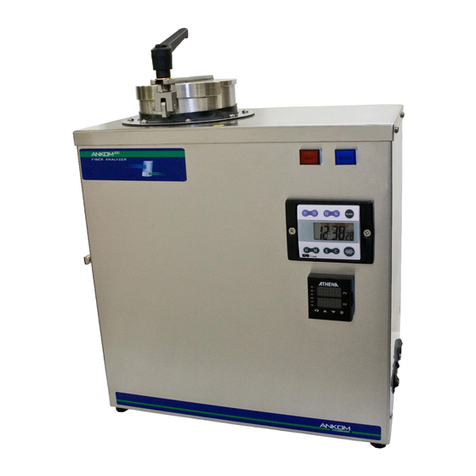
ELTRA ELEMENTRAC ONHp2 User manual

© Eltra GmbH, Germany, 42781 Haan, Retsch-Allee 1-5, Germany | 06.10.2021 Version 0005
Operating instructions
ELEMENTRAC ONHp2
Translation

Table of contents
2
Copyright
© Copyright by
Eltra GmbH
Retsch-Allee 1-5
42781 Haan
Germany

Table of contents
3

Table of contents
4
Table of contents
Table of contents............................................................................................................................................. 4
1Additional operating instructions........................................................................................................ 6
1.1 Explanations of signs and symbols ................................................................................................... 6
1.2 Disclaimer.......................................................................................................................................... 6
1.3 Copyright............................................................................................................................................ 6
2Safety...................................................................................................................................................... 7
2.1 Explanations of the safety instructions .............................................................................................. 8
2.2 General safety instructions ................................................................................................................ 9
2.3 Repairs............................................................................................................................................. 10
2.4 Intended use.................................................................................................................................... 10
2.5 Improper use.................................................................................................................................... 10
2.6 Safety symbols on the device.......................................................................................................... 11
2.7 Emergency stop............................................................................................................................... 12
2.8 Remaining safety hazards ............................................................................................................... 12
3Description........................................................................................................................................... 18
3.1 Analyser ONH-p 2............................................................................................................................ 18
3.1.1 Front side..................................................................................................................................... 18
3.1.2 Rear side of the analyser............................................................................................................. 20
3.1.3 Auto cleaner................................................................................................................................. 22
4Installation............................................................................................................................................ 23
4.1 Transport and unpacking................................................................................................................. 23
4.2 Setting up......................................................................................................................................... 25
4.3 Filling the reagent tubes .................................................................................................................. 27
4.4 Providing the gas supply.................................................................................................................. 29
4.5 The cooling water supply is provided .............................................................................................. 30
4.5.1 Connecting the supplied heat exchanger .................................................................................... 30
4.5.2 Connection of a third-party heat exchanger ................................................................................ 31
4.6 Connect the device to the PC.......................................................................................................... 33
4.7 Provide power supply ...................................................................................................................... 33
4.8 Installing the auto cleaner (optional)................................................................................................ 34
5Commissioning.................................................................................................................................... 38
5.1 Commissioning and setting up the ELEMENTRAC ONH-p 2 ......................................................... 38
5.2 Commissioning and setting up the auto cleaner (optional) ............................................................. 38
6Operation of the device ...................................................................................................................... 41
7Technical data...................................................................................................................................... 44
7.1 Technical data ELEMENTRAC ONH-p 2 ........................................................................................ 44
7.2 Name plate ELEMENTRAC ONH-p 2 ............................................................................................. 46
7.3 List of standards............................................................................................................................... 47
8Troubleshooting on the ELEMENTRAC ONH-p 2............................................................................. 48
9Cleaning ............................................................................................................................................... 48
9.1 Exterior cleaning.............................................................................................................................. 48
9.2 Cleaning the dust trap...................................................................................................................... 49
9.2.1 Cleaning the sinter filter............................................................................................................... 49
9.3 Cleaning the furnace area ............................................................................................................... 50
10 Maintenance......................................................................................................................................... 51
10.1 Overview of the maintenance work.................................................................................................. 51
10.2 Removing and installing of reagent tubes ....................................................................................... 53
10.3 Reagents.......................................................................................................................................... 57
10.4 Replacing the reagent tube of the catalyst furnace......................................................................... 58
10.5 Filling of reagent tubes .................................................................................................................... 61

Table of contents
5
10.5.1 Overview of the reagent tubes................................................................................................. 62
10.5.2 Fill the reagent tube of the catalyst.......................................................................................... 63
10.5.3 Fill the reagent tube of the gas processing (thermal conductivity cell, carrier gas)................. 64
10.5.4 Fill the dust trap of the reagent tube........................................................................................ 65
10.5.5 Filling the reagent tube of the water trap................................................................................. 66
10.5.6 Filling the reagent tube of the CO converter............................................................................ 67
10.6 Replacing the O-rings...................................................................................................................... 67
10.7 Maintenance in the furnace area..................................................................................................... 68
10.7.1 Changing the seal of the upper furnace closure...................................................................... 68
10.7.2 Changing the seal of the lower furnace lock............................................................................ 70
10.7.3 Replacing the upper electrode................................................................................................. 71
10.7.3.1 Replacing an electrode.................................................................................................... 71
10.7.3.2 complete electrode replacement, including screws......................................................... 73
10.7.4 Replace lower electrode (graphite tip)..................................................................................... 76
10.8 Replacing the brush of the auto cleaner.......................................................................................... 77
11 Spare parts........................................................................................................................................... 78
11.1 Spare parts Analyser ....................................................................................................................... 78
11.1.1 Front side of the device ........................................................................................................... 78
11.1.2 Front side (Interior view).......................................................................................................... 79
11.1.3 Lower furnace.......................................................................................................................... 81
11.1.4 Upper furnace.......................................................................................................................... 82
11.1.5 Rear side of the device............................................................................................................ 83
11.1.6 Left side of the device.............................................................................................................. 84
11.1.6.1 Left side, DevGate........................................................................................................... 85
11.1.6.2 Left side, inlet valves ....................................................................................................... 86
11.1.6.3 Valve block, compressed air control................................................................................ 87
11.1.7 Right side of the device ........................................................................................................... 88
11.1.8 Upper mounting plate .............................................................................................................. 89
11.2 Auto cleaner spare parts.................................................................................................................. 91
11.3 Fuses............................................................................................................................................... 93
11.4 Consumables................................................................................................................................... 93
11.5 Consumables for auto cleaner......................................................................................................... 93
12 Decommissioning................................................................................................................................ 94
13 Storage ................................................................................................................................................. 94
14 Disposal................................................................................................................................................ 95

Additional operating instructions
6
1 Additional operating instructions
These operating instructions are a technical manual for the safe operation of the device. Please
read these operating instructions carefully before installing, commissioning and operating the
device. Reading and understanding these operating instructions is a prerequisite for the safe and
proper use of the device.
This operating instructions do not include any repair instructions . If anything is unclear or if you
have questions about these instructions or the device as well as in case of any defects or
necessary repairs, please contact your supplier or directly the Eltra GmbH.
For more information about your device, please visit the device-specific pages at www.eltra.com.
Revisions status
The document revision 0005of the operating instructions “ELMENTRAC ONH-p 2” has been
prepared in accordance with the Machinery Directive 2006/42/EC.
1.1 Explanations of signs and symbols
The following signs and symbols are used in these operating instructions:
Signs
Meaning
Additional or further information is
available here..
Further or additional information.
1. First instruction.
2. Following instruction.
Result.
Numbered paragraphs contain sequential
instructions. An instruction may end with a result.
Tab 1: Used signs and symbols
1.2 Disclaimer
Diev orliegende Bedi enungsanleitung wurd emi tg rößter Sorgfalt erst ellt.T echnische Änd erungen sind vorbeh alten.F ür Personensc häden, die aus der Nic htbefolgung der Sicherh eits- und Warnhinweis ei n dieser Bedienungs anleitung resultier en,wi rd keine Haftung über nommen. Für Sac hschäden, die aus der Nich tbefolgung der Hinweis ei n dieser Bedienungs anleitung resultieren, wi rdk eine Haftung übernomm en.
These operating instructions have been prepared with the greatest care. Technical changes
reserved. No liability is assumed for any personal injuries resulting from non-compliance with the
safety instructions and warnings in this operation manual. No liability is assumed for any property
damages resulting from non-compliance with the instructions in this operation manual.
1.3 Copyright
These operating instructions or parts thereof may not be reproduced, distributed, edited or copied
in any form without prior written permission of Eltra GmbH. Any violation may result in claims for
damages.

Safety
7
2 Safety
Safety officer
The operator himself must ensure that the commissioned individuals working on the device
−have taken note of and understood all safety regulations,
−are aware of all the instructions and regulations of the target group relevant to them before
starting any work,
−have easy access to the operating instructions of this device at any time and without any
problems and
−have been made familiar with the safe and intended use of the device before starting any
work on the device, either through a verbal introduction by a competent person and/or
through these operating instructions.
Improper operation may cause personal injury. The operator himself is responsible for his own
safety as well as for the safety of his employees. The operator himself must ensure that no
unauthorised person has access to the device.
Target group
All persons who operate, clean, work with or on the device.
This device is a modern, high-performance product of the Eltra GmbH and was developed
according to the latest state of the art. Operational safety is ensured if this device is used in
accordance with its intended purpose and if the operating instructions provided here are followed.
Persons who are under the influence of intoxicants (medication, drugs, alcohol) or who are
overtired are not allowed to operate the device or work on it.

Safety
8
2.1 Explanations of the safety instructions
The following warnings in this operating instructions indicate potential hazards and damages:
DANGER
D1.0000
Risk of fatal injuries
Source of danger
−Possible consequences if the danger is ignored.
•Instructions and advices on how to avoid the hazard.
Failure to observe the warning “Danger” may result in fatal or serious injuries. There is a very
high risk of a life-threatening accident or permanent injury. The signal word DANGER is
additionally used in the running text or in the handling instructions.
WARNING
W1.0000
Risk of life-threatening or serious injuries
Source of danger
−Possible consequences if the danger is ignored.
•Instructions and advices on how to avoid the hazard.
Failure to observe the warning instruction “Warning” may result in life-threatening or serious
injuries. There is an increased risk of a serious accident or potentially fatal injury. The signal
word WARNING is additionally used in the running text or in the handling instructions.
CAUTION
C1.0000
Risk of injury
Source of danger
−Possible consequences if the danger is ignored.
•Instructions and advices on how to avoid the hazard.
Failure to observe the warning instruction “Caution” may result in moderate of minor injuries.
There is a medium or low risk of accident or personal injury. The signal word CAUTION is
additionally used in the running text or in the handling instructions.
NOTICE
N1.0000
Type of property damage
Source of property damage
−Possible consequences if the notices are not observed.
•Instructions and notices on how to prevent property damage.
Failure to observe the notice may result in property damages. The signal word NOTICE is
additionally used in the running text or in the handling instructions.

Safety
9
2.2 General safety instructions
CAUTION
C2.0002
Risk of injury
Ignorance of the operating instructions
−The operating instructions contain all safety-relevant information. Failure
to observe the operating instructions may therefore cause injuries.
•Please read these operating instructions carefully before operating
the device.
CAUTION
C3.0015
Risk of injury
Improper changes to the device
−Improper changes to the device may cause injuries.
•Do not make any unauthorised changes to the device.
•Use exclusively spare parts and accessories which have been
approved by the company Eltra GmbH!
NOTICE
N2.0012
Changes to the device
Improper modifications
−The conformity to the European directives declared by Eltra GmbH shall
lose its validity through improper modification. Any warranty claims shall
become void.
•Do not make any unauthorised modifications to the device.
•Use exclusively spare parts and accessories which have been
approved by Eltra GmbH.

Safety
10
2.3 Repairs
This operating instructions do not include any repair instructions. For safety reasons, repairs may
only be carried out by Eltra GmbH or an authorised representative as well as by qualified service
technicians.
In case of any repair, please contact…
…the representative of Eltra GmbH in your relevant country,
…your supplier, or
…directly the Eltra GmbH.
Service address:
Eltra GmbH
Retsch-Allee 1-5
42781 Haan
Germany
+49 2104 2333-444
www.eltra.com
2.4 Intended use
This device is used for the thermal digestion and subsequent determination of the
element content of metallic samples. The device may only be used in the laboratory by
appropriately trained and instructed personnel.
2.5 Improper use
Using the device in the private sector as well as for applications other than those mentioned in
Section „Intended use“is not permitted. Any repairs and modifications may only be carried out by
the company Eltra GmbH or an authorised representative and by qualified service technicians.

Safety
11
2.6 Safety symbols on the device
Safety symbols on the ONH-p 2 device warn of potential hazards when operating the device.
The following safety symbols can be found on the analyser:
Figure 1: Safety symbols on the analyser
2
5
4
1
3
6

Safety
12
Position
Component
Description
1,3,6
The warning symbols
1: in the rear area of the cover plate
3: in the upper, central area of the right side
wall
6: On the door at the rear side of the device
there is a warning symbol attached which
means that these covers may only be
opened by qualified personnel.
2
This warning symbol in the area of the
catalyst furnace warns of burns to fingers
and hands.
4, 5
The warning symbols on the furnace
opening warn of burns and the risk of
crushing fingers or hands.
2.7 Emergency stop
The emergency stop is controlled via the main switch of the device.
In case of an emergency, the device can be switched off as follows:
1. Turn the main switch of the analyser to switch position 0.
2.8 Remaining safety hazards
DANGER
D2.0005
Danger to life from electric shock
Exposed electrical contacts –High voltage
−An electric shock can cause severe injuries in the form of burns, cardiac
arrhythmias, respiratory arrest or cardiac arrest.
•Any work on the device may only be carried out by qualified service
personnel.
•Turn the power switch of the analyser to position 0 and pull the
mains plug out of the socket.
WARNING
W2.0015
Danger to life from electric shock
Connection to socket without protective conductor
−When connecting the device to sockets without a protective conductor, life-
threatening injuries from electric shock may occur.
•Operate the device exclusively on sockets with a protective conductor
(PE).

Safety
13
WARNING
W3.0002
Danger to life from electric shock
Damaged power cable
−Operating the device with a damaged power cable or plug can lead to life-
threatening injuries from electric shock.
•Before operating the device, check the power cable and plug for any
damage.
•Never operate the device with a damaged power cable or plug!
WARNING
W4.0017
Risk of injury
Hazardous chemicals
−When working on the device, hazardous chemicals can cause fatal
poisoning or severe skin burns.
•Please observe the safety data sheet in terms of the substances used.
•Please wear your personal protective equipment.
•Never eat or drink within the immediate vicinity of chemicals.
WARNING
W5.0021
Fire hazard / Risk of burns
Hot parts (crucibles, reagents,...) can fall down
−Ignition of tables, floors or any other surface on which the hot parts can fall.
−Ignition of clothing and other materials.
•Set up the device in a fire-proof environment. Please pay particular
attention to the table, the floor and any other surface in the immediate
vicinity of the device.
•Always wear suitable work clothing.
•Keep the work area free from any materials that could catch fire.

Safety
14
WARNING
W6.0000
Danger of poisoning
Toxic combustion gases
−The samples are exposed to high temperatures during analysis. In this
process, harmful gaseous fission products can be released or formed from
reaction processes. These gases can escape from the gas outlet or the
furnace and cause severe poisoning.
•Connect the exhaust air outlet of the device to a suitable ventilation
system.
•Please wear your personal protective equipment.
•Please observe the safety data sheets in terms of the substances
used.
•Carry out a risk analysis regarding the hazard potential of your
samples and implement relevant protective measures.
WARNING
W7.0000
Risk of life-threatening injuries
Falling loads
−The device may only be transported or lifted with suitable aids, such forklift
or crane. Loads can fall down and cause life-threatening injuries.
•Lift and transport the device exclusively by means of suitable aids,
such as forklift or crane.
•Secure the device during transport with suitable safety belts (supplied
straps).
•Please observe the centre of gravity of the device (on the right side of
the device).
•Keep a safe distance during transport.
•Never walk or stand under suspended loads.
WARNING
W8.0003
Danger to life from electric shock
Cleaning of the device
−Any cleaning work with water on the device can lead to life-threatening
injuries from electric shock, if the device is not disconnected from the power
supply.
•Only perform cleaning work with water on the device when the device
is disconnected from the power supply.

Safety
15
CAUTION
C4.0000
Risk of injury
Moving parts
−The furnace closes after user input. Hands in the area of the opening can
be crushed when the furnace closes.
•Never reach into the oven when it is closing.
•Use crucible tongs in order to place crucibles.
CAUTION
C5.0000
Risk of injury
Moving parts
−The lock moves according to user input. Hands in the area of the upper
furnace lock can be crushed when the lock closes.
•Never reach into a moving lock.
CAUTION
C6.0092
Falling device
Incorrect installation or insufficient workplace
–The weight of the device can cause personal injury if it falls down.
•Only operate the device on a sufficiently large, sustainable, slip-
resistant and stable workplace.
•Please ensure that all feet of the device have a secure footing.
CAUTION
C7.0000
Cutting injuries
Broken glass
−Sample tubes and reagent tubes are made of glass and can break. Broken
glass can cause cutting injuries.
•Please check reagent tubes and sample tubes for any damage before
use.
•Please wear protective gloves and goggles when handling with
reagent tubes and sample tubes.
•Replace damaged reagent tubes and sample tubes.
•Do not touch broken glass with unprotected hands.
CAUTION
C8.0000
Risk of injury
Moving parts
−There are fans inside the left side of the analyser. Spinning fans can cause
injuries to fingers.
•Never reach into a rotating fan.

Safety
16
CAUTION
C9.0000
Risk of burns
Hot equipment parts
−Parts of the device can become very hot and cause burns during the
performance of any maintenance work if the waiting time for cooling is not
observed.
•Please wait until the furnace temperatures cooled down to < 40 0C
before performing any maintenance work.
•Check the furnace temperatures in the ELEMENTS software.
CAUTION
C10.0076
Risk of burns
Hot equipment parts
−Some parts of the device can become very hot and cause burns if they are
touched without protective gloves.
•Please wear heat-resistant protective gloves when handling with hot
device parts.
•Never touch hot parts of the device without suitable protective gloves.
CAUTION
C11.0093a
Risk of burns
Hot crucibles
−The crucible can be very hot after the analysis, and it can cause fires and
thus personal injuries if it comes into contact with flammable surfaces.
•Please only use suitable crucible tongs to transport used crucibles.
•Please make sure that there are no flammable materials below the
furnace opening.
•Only open the furnace after a suitable waiting time has elapsed.
•If necessary, adjust the waiting time in the program in such a way that
the sample carrier can cool down sufficiently.
CAUTION
C12.0090
Risk for eye injuries
Chemicals
−When chemicals are replaced, small particles of the chemicals can float in
the air and burn the eyes.
•Please always wear protective goggles when working with chemicals.
•Please observe the safety data sheets in terms of the chemicals used.

Safety
17
CAUTION
C13.0000
Risk of injury
Pressurised system
−The device is pressurised during operation. Removing reagent tubes during
operation may lead to an explosive escape of chemicals or sample material
and can cause injuries.
•Never remove any reagent tubes during operation.
•Use the software in order to put the device into the mode “Replace
reagents” before performing any work on the device.
CAUTION
C14.0094
Risk of burns
Hot catalyst furnace
•The furnace temperature of the catalyst furnace can be up to 800°C
during operation and cause severe burns.
•Please wear heat-resistant protective gloves when handling with the
catalyst furnace.
•Before any maintenance work can be performed, please wait until
the furnace temperature is < 40 0C.
•Check the furnace temperatures in the ELEMENTS software.
•Replace the filling of the catalyst furnace only after a sufficiently
long cooling time.
Caution
C15.0107
Weight:165 kg –The centre of gravity of the device is located on the right side.
Dimensions (WxHxD):56 x 78 x 64 cm

Description
18
3 Description
The ELEMENTRAC ONH-p 2 device is an elemental analyser. By melting samples in a pulse
furnace, the device is able to determine oxygen, nitrogen and hydrogen concentration in inorganic
samples. The gaseous combustion products are measured by infrared and thermal conductivity
cells.
3.1 Analyser ONH-p 2
3.1.1 Front side
The following figure shows the front side of the device:
Figure 2: Front side of the ELEMENTRAC ONHp2
1
2
3
4
5
6
7
8

Description
19
Position
Component
Description
1
Catalyst furnace
Is used for the processing of analysis gases
2
Reagents
Are used for the processing of analysis gases
3
Sample receipt
This is where the sample to be analysed is inserted.
4
Furnace cover
The impulse furnace is located behind the cover.
5
Dust filter
This filter removes particles from the gas flow.
6
Crucible
This is where a crucible must be placed before the
analysis.
7
Crucible carrier
8
Main switch
Position 0: Turns off the device
Position 1: Preheats the device
Position 2: Puts the device ready for analysis

Description
20
3.1.2 Rear side of the analyser
The following figure shows the rear side of the analyser:
Fig. 1: side of the analyser
1
2
3
4
6
7
8
9
10
11
12
13
5
Table of contents
Other ELTRA Measuring Instrument manuals
ELTRA
ELTRA ON-900 User manual
ELTRA
ELTRA Thermostep TGA User manual
ELTRA
ELTRA CS-2000 User manual

ELTRA
ELTRA ON-900 User manual
ELTRA
ELTRA CS-580A User manual

ELTRA
ELTRA CS-2000 User manual

ELTRA
ELTRA CS-580A User manual
ELTRA
ELTRA ELEMENTRAC CS-i User manual
ELTRA
ELTRA CS-i User manual

ELTRA
ELTRA CS-800 User manual
Popular Measuring Instrument manuals by other brands

MULTISPAN
MULTISPAN AVH-14 manual

Elenco Electronics
Elenco Electronics TWT-1 instruction manual
KMC Controls
KMC Controls SSS-1000 Series installation guide
SKF
SKF LINCOLN VP Series operating instructions
Sonin
Sonin 10275 instruction manual
UWT
UWT NivoRadar NR 7100 Series Technical Information/Instruction manual
