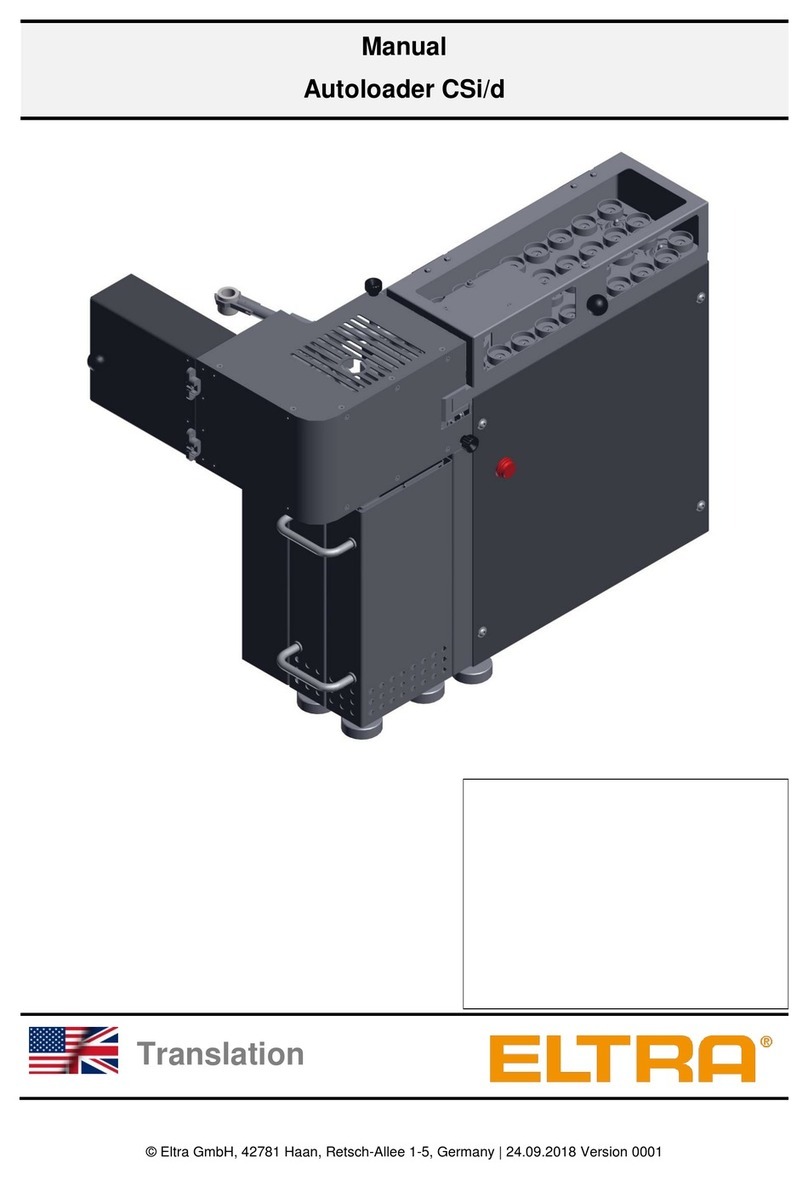
ELTRA CS-800 User manual

© Eltra GmbH, 42781 Haan, Retsch-Allee 1-5, Germany | 12.05.2017 Version 0001
Manual
Carbon and Sulfur Analyzer CS-800
Translation

2
Copyright
© Copyright by
Eltra GmbH
Retsch-Allee 1-5
42781 Haan
Germany

3
Table of Contents
1Contact information .............................................................................................................................. 6
2Notes on the Manual ............................................................................................................................. 6
2.1Explanations of the Safety Instructions ............................................................................................. 7
2.2 General Safety Instructions ............................................................................................................... 9
2.3 Explanation of signs and symbols ................................................................................................... 10
3Packaging, Transport and Installation .............................................................................................. 11
3.1 Packaging........................................................................................................................................ 11
3.2 Transport.......................................................................................................................................... 11
3.3 Intended use.................................................................................................................................... 11
3.4 Conditions for the Installation Site................................................................................................... 11
3.5 Type Plate Description..................................................................................................................... 12
4Installation............................................................................................................................................ 13
4.1 Setting check up .............................................................................................................................. 13
4.2 Front panel illustration ..................................................................................................................... 14
4.3 Mains power connections................................................................................................................ 15
4.4 Data Interface .................................................................................................................................. 16
4.5 Gas connections.............................................................................................................................. 17
4.6 Gas purification furnance connecting (optional).............................................................................. 18
4.7 Autoloader (optional) ....................................................................................................................... 19
5Analysis................................................................................................................................................ 20
5.1 Working procedure .......................................................................................................................... 20
5.2 Analysis example............................................................................................................................. 22
5.2.1 Combustion peak......................................................................................................................... 22
5.2.2 Combustion double peak............................................................................................................. 22
5.3 Work breaks..................................................................................................................................... 23
5.4 Crucibles preheating, optional......................................................................................................... 23
5.4.1 Operating the pre-heating furnace (optional)............................................................................... 24
5.5 Applications...................................................................................................................................... 24
6Maintenance......................................................................................................................................... 29
6.1 General information ......................................................................................................................... 29
6.1.1 Maintenance every 100 analyses:............................................................................................... 29
6.1.2 Maintenance every 500 analyses:............................................................................................... 29
6.1.3 Maintenance every 1000 analyses:............................................................................................. 29
6.1.4 Maintenance every 2000 analyses:............................................................................................. 29
6.2 Reagent tubes –removing and installing ........................................................................................ 30
6.3 Reagent tubes filling ........................................................................................................................ 32
6.3.1 Chemicals.................................................................................................................................... 32
6.3.2 Reagent tube filling...................................................................................................................... 34
6.3.3 Oxygen purification furnace quartz tube filling (optional) ............................................................ 37
6.3.4 Halogen trap filling (optional)....................................................................................................... 38
6.3.5 Paper filter changing.................................................................................................................... 40
6.4 O-rings replacement........................................................................................................................ 41
6.4.1 Replacing the o-rings 11 and 12 for combustion tube:................................................................ 42
6.4.2 Replacing the o-ring 13 for lower furnace lock ............................................................................ 42
6.4.3 Replacing the o-rings for furnace seal......................................................................................... 43
6.5 Furnace cleaning brush - replacing ................................................................................................. 44
6.6 Dust trap cleaning............................................................................................................................ 45
6.6.1 Fast filter cleaning........................................................................................................................ 46
6.6.2 Thorough cleaning....................................................................................................................... 47
6.7 Oxygen purification furnace refilling ................................................................................................ 48
6.8 Combustion tube replacement......................................................................................................... 49
6.9 Generator tube replacing................................................................................................................. 51

4
6.10 Combustion coil replacing................................................................................................................ 51
6.11 Pedestal removing........................................................................................................................... 51
6.12 Gas leaks checking.......................................................................................................................... 52
6.12.1 Leaks in the furnace inlet system ............................................................................................ 53
6.12.2 Leaks in the furnace ................................................................................................................ 53
6.12.3 Leaks in the furnace outlet system.......................................................................................... 54
7Function description........................................................................................................................... 55
7.1 System overview.............................................................................................................................. 55
7.2 Measuring principle.......................................................................................................................... 55
7.3 Gas flow system .............................................................................................................................. 56
7.4 Infrared cell...................................................................................................................................... 58
7.5 Furnace............................................................................................................................................ 59
8Miscellaneous...................................................................................................................................... 60
8.1Ordering numbers............................................................................................................................ 60
8.1.1 Chopper motor............................................................................................................................. 60
8.1.2 Infrared cells ................................................................................................................................ 61
8.1.3 Front side..................................................................................................................................... 62
8.1.4 Right side:.................................................................................................................................... 64
8.1.5 Pneumatics.................................................................................................................................. 66
8.1.6 Oscillating circuit.......................................................................................................................... 68
8.1.7 Furnace........................................................................................................................................ 70
8.1.8 Furnace cleaning mechanism...................................................................................................... 72
8.1.9 Gas purification furnace, optional ................................................................................................ 74
8.2 Packing............................................................................................................................................ 75
8.3 Pre-installation guide ....................................................................................................................... 77
9Approved methodologies to which Eltra instruments conform..................................................... 79
9.1 Inorganic materials (Metals) ............................................................................................................ 79
9.2 Organic materials (Oil, Coal, foodstuffs).......................................................................................... 80
10 Disposal................................................................................................................................................ 81
11 Index ..................................................................................................................................................... 82

Contact information
5

Contact information
6
1 Contact information
Please contact your local representative in the event of problems. You can find the complete
list of dealers at www.eltra.com.
Of course you can also contact ELTRA-Germany directly:
ELTRA GmbH
Retsch Allee 1-5
42781 Haan
Germany
Web: www.eltra.com
Email: service@eltra.com
2 Notes on the Manual
This Operating Manual provides technical instructions for the safe operation of the device and
contains all necessary information about the topics given in the table of contents. This technical
documentation is meant to be a tutorial and a reference. The individual chapters are self-
contained.
Knowledge of the relevant chapters (for the respective target groups defined according to
areas) is a prerequisite for the safe and correct use of the device.
This Operating Manual contains no repair instructions. In the event of any faults or necessary
repair work, please contact your supplier or Eltra GmbH directly.
Amendments
Subject to technical changes.
Copyright
The forwarding or duplication of this documentation and the recycling and passing on of its
content are only permitted with the explicit consent of Eltra GmbH.
Any infringements of this constitute an obligation to pay damages.

Notes on the Manual
7
2.1 Explanations of the Safety Instructions
In this Operating Manual we give you the following safety warnings
Mortal injury may result from not following these safety warnings. We give you the following
warnings and corresponding content.
DANGER
Type of danger / personal injury
Source of danger
–Possible consequences if the dangers are not observed.
•Instructions on how the dangers are to be avoided.
We also use the following signal word box in the text or in the instructions on action to be taken:
DANGER
Serious injury may result from not following these safety warnings. We give you the following
warnings and corresponding content.
WARNING
Type of danger / personal injury
Source of danger
–Possible consequences if the dangers are not observed.
•Instructions on how the dangers are to be avoided.
We also use the following signal word box in the text or in the instructions on action to be taken:
WARNING
Moderate or mild injury may result from not following these safety warnings. We give you the
following warnings and corresponding content.
CAUTION
Type of danger / personal injury
Source of danger
–Possible consequences if the dangers are not observed.
•Instructions on how the dangers are to be avoided.
We also use the following signal word box in the text or in the instructions on action to be taken:
CAUTION
In the event of possible property damage we inform you with the word “Instructions” and the
corresponding content.
NOTICE
Nature of the property damage
Source of property damage
–Possible consequences if the instructions are not observed.
•Instructions on how the dangers are to be avoided.

Notes on the Manual
8
We also use the following signal word in the text or in the instructions on action to be taken:
NOTICE

Notes on the Manual
9
2.2 General Safety Instructions
CAUTION
C1.0002
Read the manual
Non-observance of the operating instructions
The non-observance of this manual can result in personal injuries.
•Read the manual before using the device.
•The adjacent symbol indicates the necessity of knowing the
contents of this manual.
Target group:
All activities required for correct use are described in this Operating Manual. Any activities that
go beyond this may only be performed by authorised electricians who have received in-depth
training for this analyzer.
As the operating company, you must ensure that the following applies to the persons working
on the analyzer;
•Operating personnel have been made aware of and have understood all safety
regulations;
•Operating personnel are familiar when starting work with all handling instructions and
regulations that apply to the relevant target group for them;
•Operating personnel have access at all times to the technical documentation of this
analyzer;
•New personnel are familiarised with the safe and intended use of the analyzer before
starting work on it by means of a verbal introduction by a competent person and using
this technical documentation.
Incorrect operation can result in injury and damage to property. You are responsible for your
own safety and for that of your employees.
Ensure that no unauthorised persons have access to the analyzer.
CAUTION
C2.0089
Changes to the machine
Changes to the machine may lead to personal injury.
•Do not make any change to the analyzer and use spare parts and
accessories that have been approved by Eltra exclusively.
NOTICE
N1.0074
Changes to the machine
Improper modifications
The conformity declared by EltraEltra GmbH with the European Directives
will lose its validity.
Any warranty claims will be terminated.
•Do not make any modification to the machine.
•Use spare parts and accessories that have been approved by EltraEltra
GmbH exclusively.

Notes on the Manual
10
2.3 Explanation of signs and symbols
Number
Symbol
Reference
Meaning
12
Danger, high voltage, electric shock
13
IEC 60417-5041
Caution, hot surface
14
ISO 7000-0434B
General hazards –see documentation
-
BGV A8 W27
Risk of crushing

Packaging, Transport and Installation
11
3 Packaging, Transport and Installation
3.1 Packaging
The packaging has been adapted to the mode of transport. It complies with the generally
applicable packaging guidelines.
3.2 Transport
NOTICE
N2.0075
Transport
Mechanical or electronic components may be damaged.
•The device must not be bumped, shaken or thrown during transport.
•The device must be transported upright
3.3 Intended use
This analyzer was designed for the analysis of mainly steel and other metals. However, a wide
variety of materials such as cement, ceramics and soil can also be analyzed.
With restrictions concerning sample weight and accuracy, also coal, rubber, plastics etc. can be
analyzed.
Depending on the application, the sample weights, accelerator(s) and settings on the analyzer
can significantly influence the accuracy and precision of the measured values.
Use is only permitted in the laboratory by appropriately trained and briefed personnel.
All other applications are prohibited, in particular use in non-industrial areas.
3.4 Conditions for the Installation Site
Requirements regarding the operating conditions:
–For indoor use only.
–Operation up to max. 2,000 m above sea level.
–Ambient temperature of between 5°C and 40°C.
–Maximum relative air humidity < 80 % (at ambient temperatures ≤31°C), with linear
decrease up to 50% relative air humidity at 40°C, non-condensing.
–A residual current operated device (RCD), and a corresponding fuse (30 mA).
WARNING Provide an external fuse when connecting the mains lead to the mains in
accordance with the regulations at the installation site.
–Information about the required voltage and frequency of the device can be found on the
type plate .
–The data listed must be consistent with the existing power supply system.
–The device may only be connected to the power supply system using the connecting lead
supplied.
NOTICE
N3.0022
Electrical connection
Failure to heed the data on the type plate
Electronic and mechanical components may be damaged.
•Only connect the device to a power supply system that is consistent
with the data on the type plate.

Packaging, Transport and Installation
12
–Fluctuations of the mains supply voltage up to ± 10 %.
–The device must be operated in accordance with overvoltage category II and pollution
category 2, DIN EN 61010-1.
–Industrial environment in accordance with DIN EN 61010-1
3.5 Type Plate Description
NOTICE
N4.0022
Electrical connection
Failure to observe the values on the type plate
Electronic and mechanical components may be damaged.
•Connect the device only to mains supply matching the values on the
type plate.
Fig. 1: Type plate
1
Device designation
2
Serial number
3
Year of manufacture
4
Voltage definition
5
Amps
6
Power
7
Manufacturer’s address
8
Item number
9
Mains frequency
10
Protection type
11
Disposal label
12
CE mark
Please quote the device designation (1), the serial number (2) of the device and the item
number (7) if you have any queries.

Installation
13
4 Installation
4.1 Setting check up
CAUTION
V0092
Device falling down
Incorrect erection or inadequate working space
–Due to its weight, the device can cause injuries if it falls down.
•Only operate the device on a sufficiently large, strong, non-slip and
stable working area.
•Ensure that all feet of the device are standing securely.
WARNING
W1.0021
Fire hazard / Risk of burns
Hot parts (crucibles, reagents,...) can fall down
Ignition of tables, floors, or any other surface the hot part falls on
Ignition of clothes and any other material
•Set up the analyser in a flame retardant environment. Pay special
attention to the table, the floor and any other surface being in the near
of the analyzer
•Always wear suitable clothing
•Keep the work environment clear of all materials that could catch fire
NOTICE
Installation of the machine
–It must be possible to disconnet the machine from the mains at any time.
•Install the machine such that the connection for the mains cable is
easily accessible.
Since the analyzer weighs about 85 kg it should be placed on a suitably stable surface. The
balance should also be placed on a surface which is free of vibrations. The balance can be
placed in any location, although positioning the balance to the right of the analyzer is proven to
be best suitable. The balance can of course also be placed on a weighing table next to the
analyzer. There are no special requirements for setting up the printer and computer; they can
be placed on a normal desk.

Installation
14
Fig.
2
: Example of installation
Although the analyzer’s operating environment does not necessarily need to be air conditioned,
it is advisable to keep the room temperature between 18°C and 30°C.
Under no conditions should the device be exposed to direct sunshine!
Avoid places exposed to the wind of air conditioners or to the wind blowing through open
windows or doors.
4.2 Front panel illustration
Fig.
3
: Front view
2
4
5
6
7
13
12
15
9
10
11
1
8
14
3

Installation
15
1
Catalyst furnace
2
Oxygen pressure gauge (norm. 1,5 bar)
3
Infrared cell purge 10 l/h
4
Regulator for infrared cell purge (3)
5
Carrier gas flow
6
CO2/ H2O –trap
7
Button for leakage test
8
Mains power switch
9
Dust filter
10
Cover attachment knobs
11
Furnace cover
12
H2O –trap
13
Compressed air gauge (norm. 5 bar)
14
Dust filter cartridge
15
SO3- trap
4.3 Mains power connections
Since the infrared cell requires about 1 hour to reach a stable operation temperature, it is
advisable to connect the analyzer to the mains power first immediately switch it on before
further installation work is carried out.
This waiting time is only necessary when switching on the analyzer from cold condition. It is
then normally not switched completely off, in order to always be at constant operation
temperature. During long work breaks, the analyzer is on stand-by, which is on position 1 of the
mains power switch.
Fig.
4
: Mains power connection - rear view
1
2
3
4
5
6
7

Installation
16
1
Balance
2
Analyzer
3
Analyzer mains plug
4
Quad power socket
5
Computer
6
Monitor
7
Printer
First connect the analyzer to the mains power and switch it on to position 1 in order to win time.
The power switch is located on the front panel in the low left hand corner. Set to position 1. The
reason why to first switch on the analyzer is for the infrared detectors to have time to stabilize
their temperature while cable connections and software start are made.
4.4 Data Interface
Fig.
5
: Data interfaces
1
Spare serial interface
2
PC connection (serial interface (COM-port))
3
Analog input/output signals
4
Digital input/output signals
5
Autoloader connection
When all devices are connected to the mains power, then data connections can be made. The
plugs are all different to each other, so that they cannot be interchanged. The required data
cables are included in the boxes of additional peripheral devices supplied with the analyzer.
These are adapted to the interfaces when the analyzers are put into operation in our company.
The serial interface of the balance is programmed in order to match the required configuration
for weight transfer to the PC.
The computer is already provided with an operating system and software for controlling the
analyzer.
1
2
3
4
5

Installation
17
NOTICE
For information about using the PC for operating the analyzer, refer to the UNI-software help
manual.
4.5 Gas connections
Fig.
6
: Gas connections
1
Compressed air (4-6 bar, 60-90psi)
2
Gas outlet
3
Oxygen inlet (2-4 bar, 30-60psi)
Two gas connections are necessary to operate the analyzer. The required tubes are included in
the delivery. See above diagram.
Tube (3) for the oxygen supply is 5m long with 6mm outer diameter having a fitting with G1/4”
inner thread to be connected to the oxygen supply.
Tube (1) for the compressed air is 5m long with 4mm outer diameter having a fitting with G1/4”
inner thread to be connected to the compressed air supply.
Tube fitting (3) connects the analyzer with an oxygen bottle via a pressure regulator. This
connection must be very secure, since the operating pressure in the tube is between 2 and 4
bar (30 to 60psi). Gas connection (1) is for the compressed air supply to the pneumatic cylinder
(piston) and the internal cooling for the induction coil.
Gas connection (2) is for connecting the analyzer’s exhaust to ventilation. It is mostly not used,
due to low quantities of CO2and even lower quantities of SO2resulting from the sample
combustion.
When the analyzer’s mains switch is set to position 2, a valve opens and the oxygen can flow
through the gas flow system. The flow rate is stabilized within a few seconds to 180 l/h and is
monitored on the lower flow meter.
1
3
2

Installation
18
4.6 Gas purification furnance connecting (optional)
Fig.
7
: Connecting the gas purification furnace
The tube from the pressure regulator is connected to the lower fitting of the gas purification
furnace (optional), and the tube (1) is connected on its place. See above diagram.
1

Installation
19
4.7 Autoloader (optional)
Fig.
8
: Auto loader
The CS-800 can be supplied with an automatic sample loading system. This loading system
may also be retrofitted at a later date. Unlike many other auto loaders the ELTRA system can
accommodate up to 130 samples enabling hours of unattended operation. On request, the
loader can be delivered for more or less crucibles. The auto loader, which does not occupy any
additional bench space, is mounted above the area where the balance, PC, monitor and
consumables are normally placed. The crucibles positions on the loader are easily accessible to
the operator even from sitting position. The operation of the CS-800 with an auto loader
requires a PC for easy manipulation of sample weight storage and out of sequence samples.
For instructions on installing and operating the auto loader read the Loader manual which is
delivered with the loader.

Analysis
20
5 Analysis
5.1 Working procedure
DANGER
D1.0006
Danger caused by scalding by samples
Sample material
–Damage to the respiratory tracts, skin and/or mucous membranes.
–Radiation damage.
•The user must himself assess the risk emanating from a sample during
the analysis.
WARNING
W2.0021
Fire hazard / Risk of burns
Hot parts (crucibles, reagents,...) can fall down
Ignition of tables, floors, or any other surface the hot part falls on
Ignition of clothes and any other material
•Set up the analyser in a flame retardant environment. Pay special
attention to the table, the floor and any other surface being in the near
of the analyzer
•Always wear suitable clothing
•Keep the work environment clear of all materials that could catch fire
CAUTION
C3.0093
Hot crucibles
A hot crucible can cause injuries or damage to property on contact or if it falls
down.
•Adapt the “Post waiting time” so that the crucible can cool down
sufficiently.
•Take care that no flammable materials are situated below the furnace
opening
The CS-800 was designed for the analysis of mainly steel and other metals. However, a wide
variety of materials such as cement, ceramics and soil can also be analyzed. With restrictions
concerning sample weight and accuracy, also coal, rubber, plastics etc. can be analyzed. The
sample weight, the accelerator(s) and the sensitivity of the analyzer are different, depending on
the respective sample material properties during combustion.
NOTICE
For optimum CS analysis of coal, rubber, plastics and generally organic samples, we offer CS
analyzers employing resistance furnaces. We also offer the CS-2000 which is an analyzer
having both, induction and resistance furnace for optimum analysis of both, organic and
inorganic samples.
The analysis of steel is described in the following section, as an analysis example.
Ensure that the compressed air and oxygen supplies are turned on. They should normally not
be turned off, at least during working hours when only short breaks between analyses take
place. By turning the mains power switch to position 2 the heating for the generator tube
filament and the cooling blower are switched on, as well as a valve which allows the oxygen to
enter the gas flow system. It is advisable to let the oxygen flow through the analyzer for several
minutes before beginning of analysis, so that air is purged out of the IR cells and their
Other manuals for CS-800
2
Table of contents
Other ELTRA Measuring Instrument manuals
ELTRA
ELTRA CS-i User manual
ELTRA
ELTRA CS-2000 User manual
ELTRA
ELTRA CS-580A User manual

ELTRA
ELTRA CS-800 User manual
ELTRA
ELTRA ON-900 User manual

ELTRA
ELTRA CS-2000 User manual

ELTRA
ELTRA ON-900 User manual

ELTRA
ELTRA ELEMENTRAC ONHp2 User manual
ELTRA
ELTRA ELEMENTRAC CS-i User manual
ELTRA
ELTRA Thermostep TGA User manual

