ELTRA ON-900 User manual

0
0.1
2002 by ELTRA GmbH Germany – January 2002 – Service Manual OH 900 / ON 900 / ONH 2000
0.1-2
The analysers ON - 900, OH - 900 and ONH – 2000 are of equal design.
The service manual is therefore common for all three types.
The only difference between them is the tubing and the chemicals. See 4.3
NOTE :
Servicing should only be done by a person with profession, who has mastered the
servicing and maintenance of this device, as well as having further qualifications,
especially in the field of electronics and physics.
We ask the users of this Service Manual to inform us about any possible mistakes.
We would also appreciate any suggestions for supplements and improvements to this
Service Manual.
CAUTION !
Before opening this device, always unplug the main power !

2002 by ELTRA GmbH Germany – January 2002 – Service Manual OH 900 / ON 900 / ONH 2000
0.1-3
SERVICE MANUAL ON / OH-900 and ONH-2000
0.1 Overview of the ON/OH-900; ONH-2000 modifications………………………..…0.1-5
1 FAULTS
1.1 IR cell test displays ++++ see 2. 3 .............................................................................1.1-1
1.2 No gas flow.....................................................................................................................1.2-1
1.3 The flowrate is not stable .............................................................................................1.3-1
1.4 The base line of the TC cellcannot be adjusted to zero............................................1.4-1
1.5 Analysis time too long....................................................................................................1.5-1
1.6 High blank value.............................................................................................................1.6-1
1.7 Erratic results..................................................................................................................1.7-1
1.8 The LED for the temperature regulation of the infrared cell or the thermoconductivity
cell does not flash...........................................................................................................1.8-1
1.9 No analysis start.............................................................................................................1.9-1
1.10 The message "No Water Flow" appears on the display..........................................1.10-1
1.11 Furnace temperature too high.....................................................................................1.11-1
1.12 The base line of the TC cellis negative, see 2.12 ...................................................1.12-1
1.13 No furnace power during the analysis........................................................................1.13-1
1.14 The sample drop motor does not rotate.....................................................................1.14-1
1.15 Faulty electronic drivers...............................................................................................1.15-1
1.16 Noise or drift of the infrared baseline .........................................................................1.16-1
1.17 Furnace cut-off during analysis...................................................................................1.17-1
1.18 Beeper responding.......................................................................................................1.18-1
1.19 Saved data is lost.........................................................................................................1.19-1
1.20 The upper electrode becomes dark............................................................................1.20-1
1.21 The chopper motor doesn`t rotate..............................................................................1.21-1
1.22 The samples make bubbles........................................................................................1.22-1
1.23 Spare parts kits ............................................................................................................1.23-1
1.24 Unstable current...........................................................................................................1.24-1
2 ADJUSTMENTS, TEST AND FUNCTION EXPLANATION
2.1 Gas flowcontroller adjustment and jumper settings ...................................................2.1-1
2.2 Pressure switch..............................................................................................................2.2-1
2.3 Infrared zero-baseline, control and adjustment...........................................................2.3-1
2.4 IR-source voltage setting...............................................................................................2.4-1
2.5 Temperature regulation of the IR-cell...........................................................................2.5-1
2.6 Pneumatics for furnace lift............................................................................................2.6-1
2.7 Flow rates .......................................................................................................................2.7-1
2.8 Furnace lift adjustment..................................................................................................2.8-1
2.9 Linearization ...................................................................................................................2.9-1
2.10 Balance programming:.................................................................................................2.10-1
2.11 .......................................................................................................................................2.11-1
2.12 TC zero baseline adjustment......................................................................................2.12-1
2.13 Diagnostic printout .......................................................................................................2.13-1
2.14 Temperature regulation of the TC Cell.......................................................................2.14-1
2.15 Water flowand furnace temperature sensing board ON21......................................2.15-1
2.16 The furnace control board PW13...............................................................................2.16-1
2.17
2.18 Sample drop motor and the motor switch adjustment..............................................2.18-1
2.19 Hot extraction upgrade ................................................................................................2.18-1

2002 by ELTRA GmbH Germany – January 2002 – Service Manual OH 900 / ON 900 / ONH 2000
0.1-4
3 SERVICE
3.1 IR-paths, cleaning and replacing....................................................................3.1-1
3.2 IR-source......................................................................................................3.2-1
3.3 Infrared electronics........................................................................................ 3.3-1
3.4 Infrared power supply.................................................................................... 3.4-1
3.5 Chopper ++++ see 3. 2................................................................................ 3.5-1
3.6 Infrared temperature regulation..................................................................... 3.6-1
3.7 Leak checking...............................................................................................3.7-1
3.8 Replacing the EPROMS................................................................................ 3.8-1
3.9 Clearing memory........................................................................................... 3.9-1
3.10 Electronic reset........................................................................................... 3.10-1
3.11 Coding of the IR-ranges.............................................................................. 3.11-1
3.12 Adding new IR-ranges................................................................................. 3.12-1
3.13 Cleaning the solenoid valves....................................................................... 3.13-1
3.14 Replacing the flow sensor ........................................................................... 3.14-1
3.15 Installing an AC power stabilizer.................................................................. 3.15-1
3.16 Replacing the gas pump.............................................................................. 3.16-1
3.17 Additional safety features for furnace pneumatics (optional)......................... 3.17-1
3.18 230V / 400 V operation................................................................................ 3.18-1
3.19 Upgrading of analysers with electronic rack for using the
new Windows software................................................................................ 3.18-1
4 MISCELLANEOUS
4.1 Ordering numbers.........................................................................................4.1-1
4.2 Wiring diagrams............................................................................................ 4.2-1
4.3 Water and gas flow diagrams, analysis sequence.......................................... 4.3-1
4.4 Purging of the chopper..................................................................................4.4-1
4.5 Maintenance OH- 900, ON- 900....................................................................4.5-1
2002 by ELTRA GmbH Germany – January 2002 – Service Manual OH 900 / ON 900 / ONH 2000
0.1-5
0.1 Overview of the ON/OH-900; ONH-2000
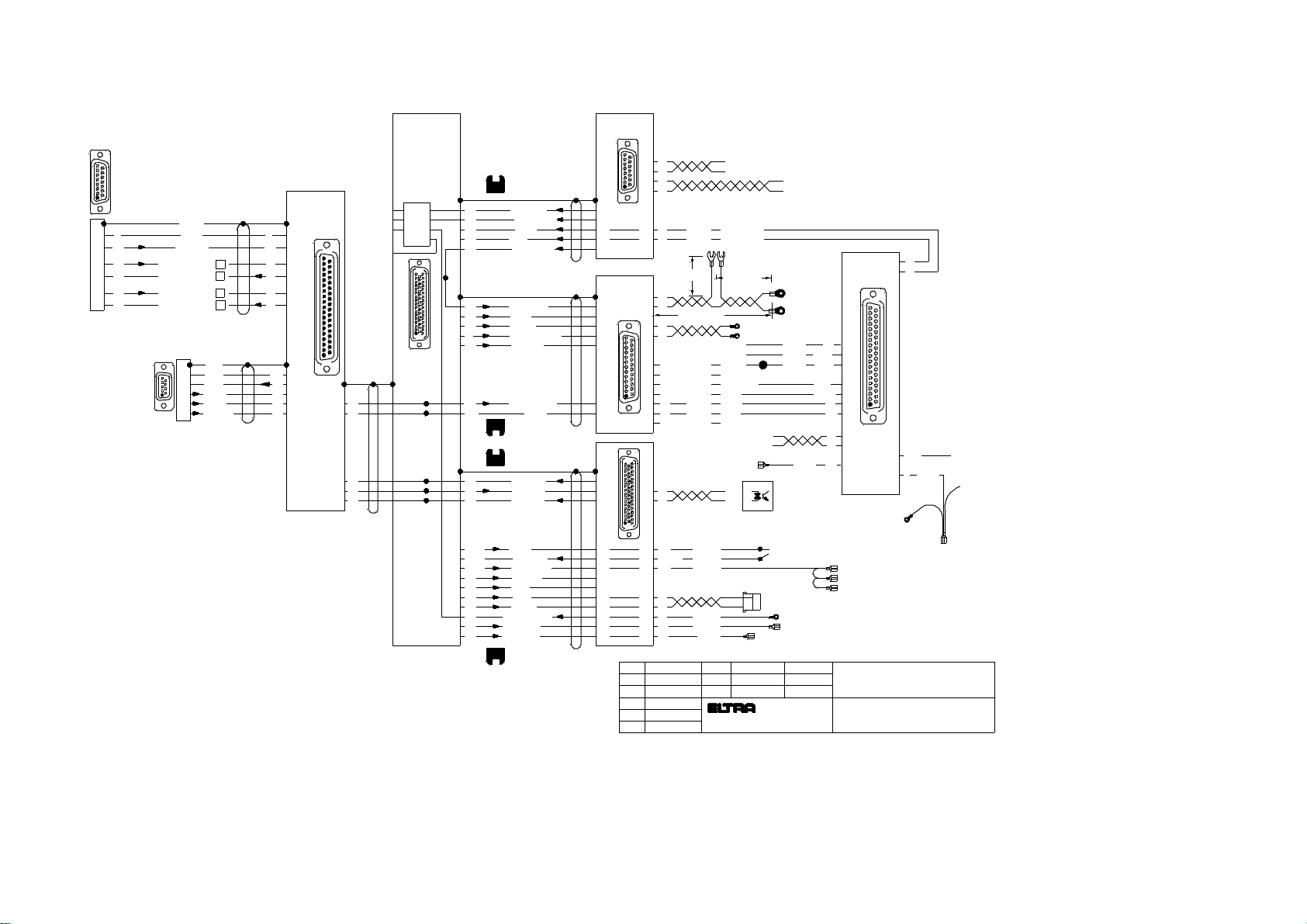
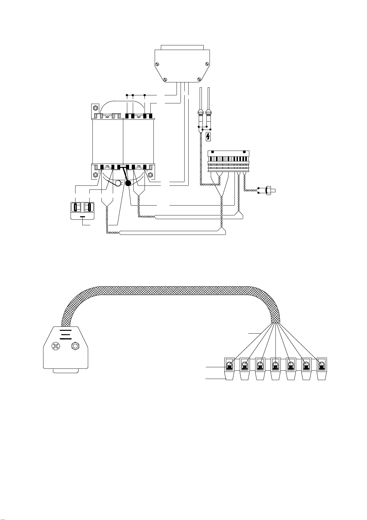
modifications:
Up to S/N 1500xxxxxx
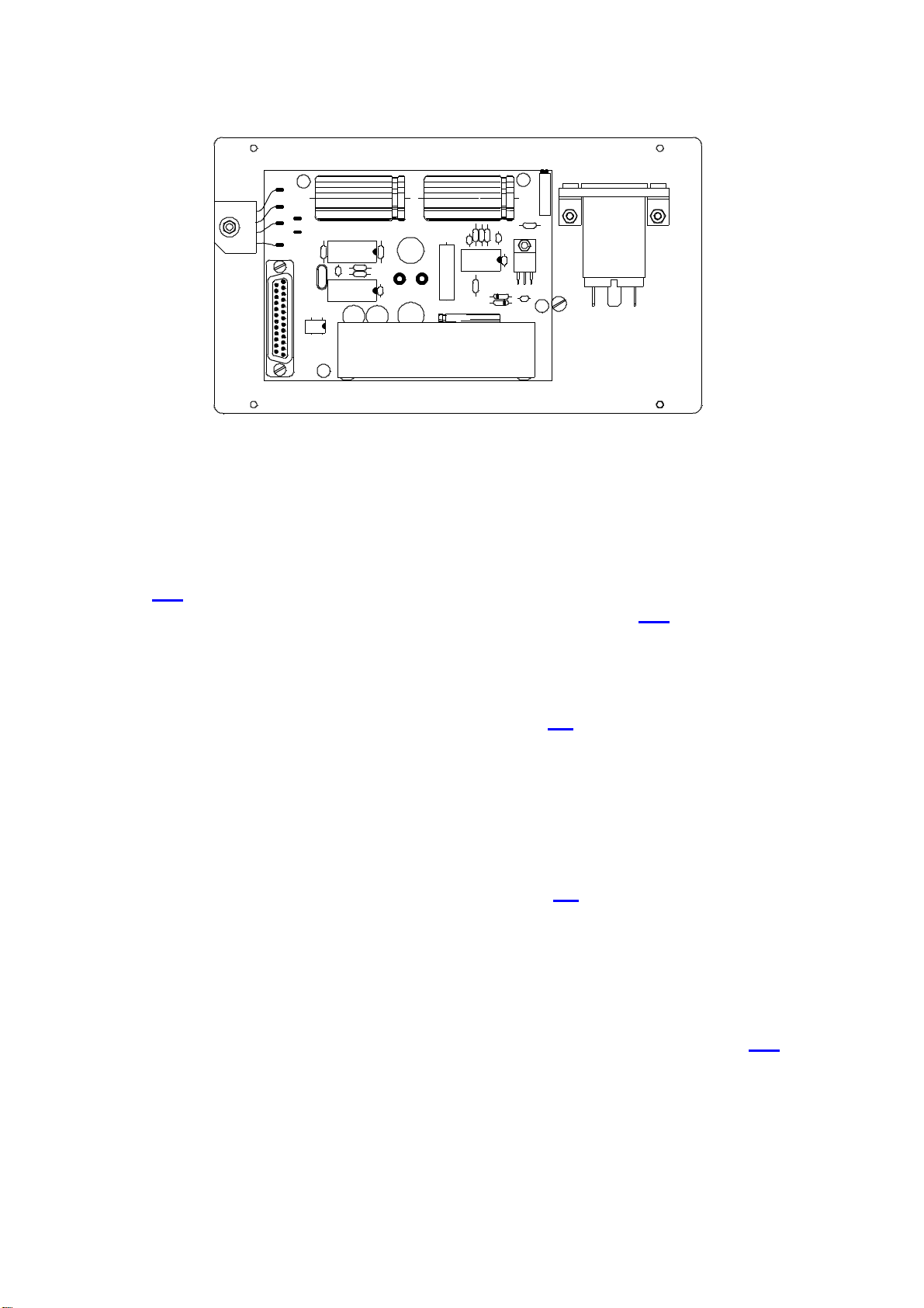
The electronic unit is replaced by the board UNI 1.3 and the electronic rack is removed.
The corresponding wiring diagram is 32007.
The modification took place in the second half of 2004.
12
1
13
9
6
5
4
3
ws
br
15
gr
23
9
17
18
48
45
2
49
12
47
sw
rs
ws
rt
br
50
46
ws
br
9
10
14
gn
ge
gr
10
19
35 20br 19
ws
2
1
6
5
gn
bl
ge
rt
18 33
34 50
17
1
8rs
7
ge
+15V
-15V
GND
GND
24+25
12+13
21
8
1 13
14 25
vi 43
8bl
+24V 22ac
GND 24ac
ge
gn
br
ws
br
gn
gr
ge
100 cm
100 cm
42 cm
Overheat
Water flow
+24V
GND
Water flow
Trigger
Power ON/OFF
Motor
+24V
Power (1V/kW)
Gas pump
Flow rate
Gas flow
GND
+24V
TC cell
Purge valve
Pneumatic
7
15
Pump control
3
2
ws/gn
bl
sw
rs/gr
13x 0.14²x105 cm abgeschirmt
GND
Flow rate
gr
br
br
gr
gn
ge
rt
gn
gn
bl
bl
49 cm
49 cm
10 GND 24acgn/rt
15
31
27
18
11 br/gr
3 ws/br
Motor
Phase
ws/gn
gn/rt
bl
sw
vi
vi
1
21
rt
bl/ws
33
7rt
Pneumatic valve 11380
Purge valve 01160
Pressure switchrs
13
11
28gr
ws/br
ws/br50 cm
50 cm
50 cm
Phase
115cm
115cm
105cm
Pressure switch
10cm
160cm Motor
20
19
1
37
Furnace current
9x 0.25²
60 cm
10x 0.25²
NR32
15038
65 cm Water temp.
ON21-32210
81
159
PW13-32066
6x 0.25²
sw
6
30 cm
140 cm
40 cm
40 cm
40 cm
40 cm
30 cm
FC21
15098
50 cm Furnace voltage
2x 0.75²
15c m
2x 0.75²
50c m
NK31- 16100
130 cm Furnace temp.
30 sw
5rt
gr
abgeschirmt
D50-Buchse-Lötseite D25-Buchse-Lötseite D15-Buchse-Lötseite
D37-Buchse -Lötseite -
8
2
4
5
1
110cm
N (Hi)
N (Lo)
GND
GND
3
33
zero
TC temp.
6 9
5
1
D9-Buchse Lötseite
Auto zero signal
2
PIN
1 TC Temp.
Low N output signal
High N output signal
4
5
2
2
GND8 GND9
TC CELL
sample drop
24V AC
GND
current sense
85cm Motor
blue
bro wn
yellow
gre y
gre en
ora nge
pink
red
blac k
vio lett
wh ite
bl
br
ge
gr
gn
or
rs
rt
sw
vi
ws
36
38
40
35
37
39
or
gn/ws
bl 100 cm
100 cm
100 cm
gr/rs
bl/rt
ws/gn
GND
H/N code
Gas saveing
C1
C3
Purge valve
H/N code switch
25500
01160
11430
11435
Gas save valves
50 cm
50 cm
5x 0.14²x25 cm
abgeschirmt
grgr
br
1
O(Lo) auto zero
2
ge
O(Lo) IR-signal
gn
ge
2
2
1br
5
1
O(Hi) IR-signal
O(Hi) auto zero
gn
6
ws ws
GND
IR temp.
14
9
81
159
IR-Cell D15-Socket solder side
GND14
PIN
9IR Temp.
High O output signal
4High O auto zero signal3
2
Low O output signal2
2
Low O auto zero signal1
2
ws
2
44
3 vi
rt 60 cm
rt
vi
5
11
4
1
20
19
37
15
14
17
34
16
13
Shield
D37-plug solderside
rs rs
18 33
34 50
17
1
FD50-Socket solder side
11
gr Water flow
6x 0.14²x130 cm
abgeschirmt
34
27
18
14
16 1
5
3
ULN
7x 0.14²x120 cm
42
36
18
39
28
37
26
20
50
41
38
40
geändert am:
D-41469 Neuss
Mainstr. 85 Block 20
Zeichnungs-Nr.:
Datum
gez.:
gepr.:
Sanda
Polemitis
Name
19.07.2004
19.07.2004
Bez.:
32007
a 21.07.2004
ON900/OH900 + ONH 2000
-UNI 1.3+1.4 Version
Signal and control cable
Benennung:
6x 0.14²x65cm
Abschirmung
5x 0,14²x55cm
b 02.12.2004
c 03.12.2004
9
15
17
16
29
13
UNI 1.3+1.4
UNI 1.3+1.4
Pressure switch
d 07.12.2004
NC
2
e 08.12.2004

2002 by ELTRA GmbH Germany – January 2002 – Service Manual OH 900 / ON 900 / ONH 2000
0.1-6
Pump 15266
Pump plate-15262
Pump control board PC1-15268
T1
BF418
100µ/350V
1765432
T5
4007
ZY200
ZY200
D8 D9 D10
D12D11
7824
T4
T3
1 2k /9 W
R5
R1
33/5W
4
3
2
5
6
7
8
TP1 TP2
TP3
TP4
50k
1 00 k
4148
56k
18k
68k
10k
220k 100k
R3
R4
R7
R8 R9
10k
1k8
1k8
T2
4007
D1
D2
C1
R2
4148
ZD33
IC1
R10
R11
R12
1k
10k
150k
150k
120k
39k
12k
15k
10k
33k
33k
47k47k
39k
R26
R16
TP7
R17
D5
D3
C7
10n 0,1
47 µ
6 3V
10n
C6
C4
TP6
4148
D6 R18
IC2
4 N 3 5
3k3
C2 R 6
ZD15
4007
P2P1
G
IRF820
TP8
TP9
NR 32
IRF820
J2
A B
1
R13
R14
R15
R19
R20
R21
R22
R23
R24
R25
R27
4007
S
C5
OP270
1k
10n/500V
+
TP5
1µ
C 3
D7
D
+
IRF820
G
S
D
- pol ige S tiftle is te a b gew in ke lt5 0
50
17
33 1
18
34
D 9 -B u c hs e
+
+ + + +
1 0µ 47µ
1 0µ 47 µ 4 7µ 1 0 0 µ
O P 4 7 0
P1 P2 P3 P4
1 2 k / 5 W
TR 1
TP3
J 1
5
9 6
1
K1
7 812782 0
TR 2
F B R 2 2 1
+
47µ
47 µ
+
F C 2 1
MD-50
To pum control board
To pum control board
Adapter 32910
ON-900 from S/N 1738xxxxxx
OH-900 from S/N 1811xxxxxx
ONH-2000 from S/N 1771xxxxxx
The pump has changed along with a pump control board and a adapter as shown below.
The boards FC21 and NR32 are replaced by the board 15268.

2002 by ELTRA GmbH Germany – January 2002 – Service Manual OH 900 / ON 900 / ONH 2000
0.1-7
ON-900
OH-900
ONH-2000
09270 old pump
Oldpumpout
-po l i ge S t iftl e i st e ab ge w i nk el t5 0
5 0
1 7
33 1
18
3 4
D 9 -Bu c h se
+
+ + + +
10µ 47µ
10µ 47 µ 47 µ 100 µ
O P 4 7 0
P1 P2 P3 P4
12 k/ 5 W
T R 1
TP3
J1
5
9 6
1
K1
78127820
T R2
F BR 2 2 1
+
47µ
47 µ
+
F C 2 1
T1
BF418
100µ/ 350V
1765432
T5
4007
ZY 200
Z Y200
D8 D9 D1 0
D1 2D11
7824
T4
T3
12 k/9W
R5
R1
33/5W
4
3
2
5
6
7
8
TP 1TP 2
TP3
TP4
5 0k
1 00k
4148
5 6k
18k
68k
10k
220k 100k
R3
R4
R 7
R8 R9
10k
1 k8
1k8
T2
40 07
D1
D2
C1
R2
4148
ZD33
IC1
R10
R11
R12
1k
10k
1 50k
150k
120k
39k
12k
1 5k
10k
33k
33k
47k47k
39k
R26
R1 6
TP7
R17
D5
D3
C7
10n 0,1
4 7µ
63V
10n
C6
C4
TP6
4148
D6 R18
IC 2
4 N3 5
3k3
C2 R 6
ZD15
4007
P2P1
G
IR F820
TP8
TP9
NR 32
IRF82 0
J 2
A B
1
R13
R14
R15
R19
R2 0
R2 1
R22
R23
R24
R25
R27
4007
S
C5
OP270
1k
10n/500V
+
TP5
1 µ
C 3
D7
D
+
IRF820
G
S
D
Two
boards
out
NR-32
FC-21
15266 pump
15268 electronic
board
15264 supporting
panel
Newpumpin
withboard+panel
Adapterin
32910 adapter
The old pump is change with the new pump as shown below.
Ordering numbers:
15264-Pump plate
15266-Pump
15268-Pump control board PC1
32910-Pump adapter

2002 by ELTRA GmbH Germany – January 2002 – Service Manual OH 900 / ON 900 / ONH 2000
0.1-8
60250
60525
60552 60552
upwards
downwards
60500 silver
60500 nature
60234
60525
60513
60522
60236
60566
60500 blue
72010
2,5bar
60566
60500
green
60500 blue(L=3cm)
60531
60566
From end of the year 2007 the ON/OH-900 and ONH-2000 are equipped
with the new pneumatics.

2002 by ELTRA GmbH Germany – January 2002 – Service Manual OH 900 / ON 900 / ONH 2000
1.1-1
1
1
FAULTS
1.1
1.1
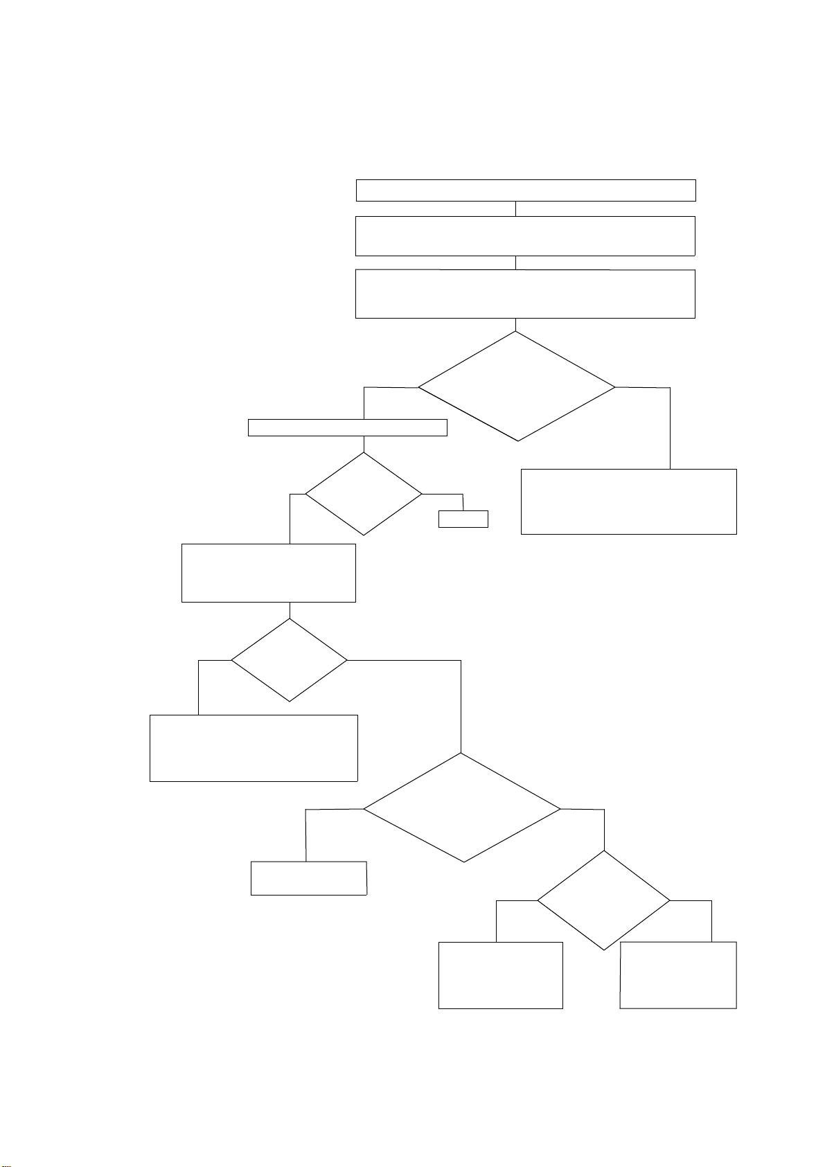
IR-cell test displays: ++++ see 2. 3
also after five minutes of oxygen flow:
If the range is higher than
10 V ++++
then the problems are as follows:
1) Too much contamination:
There are one or more
indication ranges and they
are too high.
2). The IR–sources:
The sources are bent or
de-adjusted through
transport. See Remark:
3).Chopper:
The chopper is not running
although the path is not
contaminated and the IR-source´s
is ok.
Remark:
In most cases the problem is
in the IR-sources or in the
power supply. During a rough
transportation the IR-sources
may be bent causing the
problem. See 3.2. We
experienced that this is very
popular for the new IR-detector
and preamplifiers.
We can only help if you send
us a copy of the flow diagram of this chapter, after drawing a line along the path you
followed according to the condition you found.
Asking for detectors, preamplifiers and boards without following this diagram, is useless.
P1
06421 IR13
I R1 3 0 64 2 0
1
1 - 1- 2
Check the IR
source voltage
see
Check the chopper.
For this,
remove the
IR Path. see
Ceck the position
of the IR-sources
see
< Menu > < Cal > displays ++++
Replace the
power supply.
see
IR Source
is defective.
see
Is the
rectifier
warm
yes
no yes
Feel the rectifier (1)
no
Adjust the
IR Source
voltage see
Adjust the zero
see Check if there
is 1-1,5 VAC
on TP1,board IR21
see
Still
faulty
Does the
chopper
run
no
Replace the
spring see
Replace the
chopper motor
see
no yes
yes
no yes
Replace the
IR21 board
see
Voltage
correct
1-1 S
Too
low or
zero
Zero
Replace path
see
Check for
contaminated
IR - path
Too low
Replace the
IR preamplifier
see and
Check for proper
Cable connection
to IR21 board
Replace the
IR detector, see
Attention!
Consider the detector
only as a last resort!
If after replacing the
detector the fault still
exists, then reinstall
the old detectors
Is there
any
voltage
?
3.1
3.2
2.4
?
3.4 3.2 ?
3.5 2.4
3.5
?
2.3
2.3
?
?
3.1
3.3
2.3 3.1
3.1
2002 by ELTRA GmbH Germany – January 2002 – Service Manual OH 900 / ON 900 / ONH 2000
1.1-2
Touch the rectifier ( 1 ) of the IR-cell, it should feel warm ( about 45°C ).
( The analyser does not need to be turned off, nor must the infrared rack be removed ).
If the rectifier is cold ( room temperature ), you should check the IR-source voltage,
see 2. 4 .
If there is no IR source voltage, replace the power supply, see 3. 4
If there is IR source voltage, but the rectifier ( 1 ) is cold, then the IR source is
defective.
Since the IR sources are connected in series, the rectifier is cold, even when just one
of the IR sources is defective.
Open the infrared rack, remove the IR source ( see 3.2 ), and identify the defective
part by resistive measurement.
Non defective IR sources have a resistance of only 1 Ohm, while defective ones have
a much higher or unmeasurable resistance.
CAUTION!
When setting new IR sources, CO2can be produced during the first warming up.
Therefore, all points of the adjustment instructions ( see 2.3 ) should be carefully followed
through.
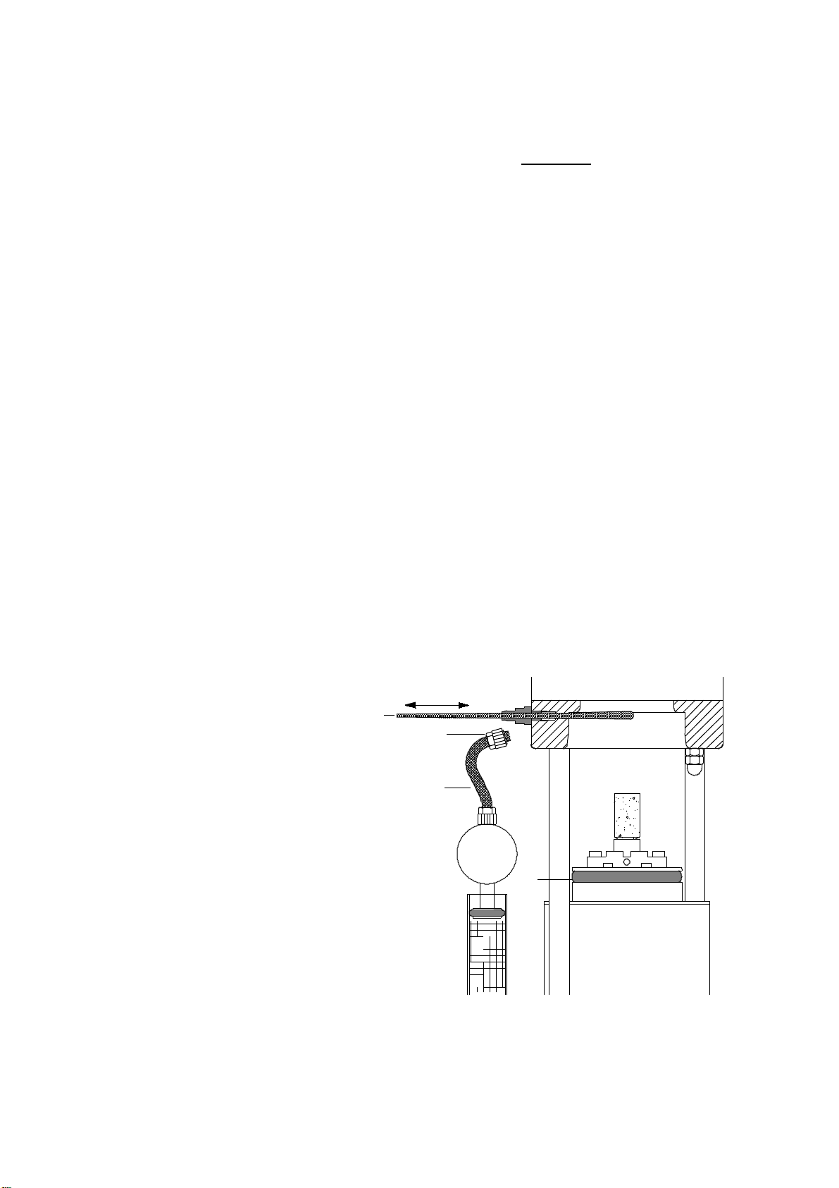
If the rectifier ( 1 ) is warm, then check if the chopper motor is at a standstill. To do
this, an IR path must be unscrewed.
Through the bore holes in the chopper motor housing, the chopper blades should be
be visibly rotating.
The cause for a chopper motor that doesn't run are usually the springs ( see 3. 5 ) that
were built in before September 1993 .
Exchange the spring-type for a newer type. The motor itself should turn anyway, even
when the chopper blade is not mounted. If not, the motor is defective.
Theoretically, the circuit board IR21 may also be at issue. This is, however, very
unlikely if more than one channel is not functioning in a multi-channel device.
P1
06421 IR13
I R 13 0 6 4 20
1
1- 1 - 2
2002 by ELTRA GmbH Germany – January 2002 – Service Manual OH 900 / ON 900 / ONH 2000
1.1-3
TC-cell check displays ++++ or -9.99 ( see 2 .12 )
If the test of the TC-cell still shows ++++ or - 9.99 after 5 minutes of carrier gas flow,
check the flow rates first ( see 2 .12) .
If they are OK, watch the zero baseline of the nitrogen channels and adjust them if
necessary.
If it is not possible to get a straight baseline by using the jumper and trimmer ( see 2 .12 ),
check the resistance of the thermistors.
Unplug the connector of the TC-cell and open the metal block of the TC-cell.
Connect an ohmmeter across each thermistor ( don't open any connection ).
The expected reading should be approximately 5-6 KOhm.
In case you should measure more than 14 KOhm across one specific thermistor, then that
thermistor is faulty and must be replaced.
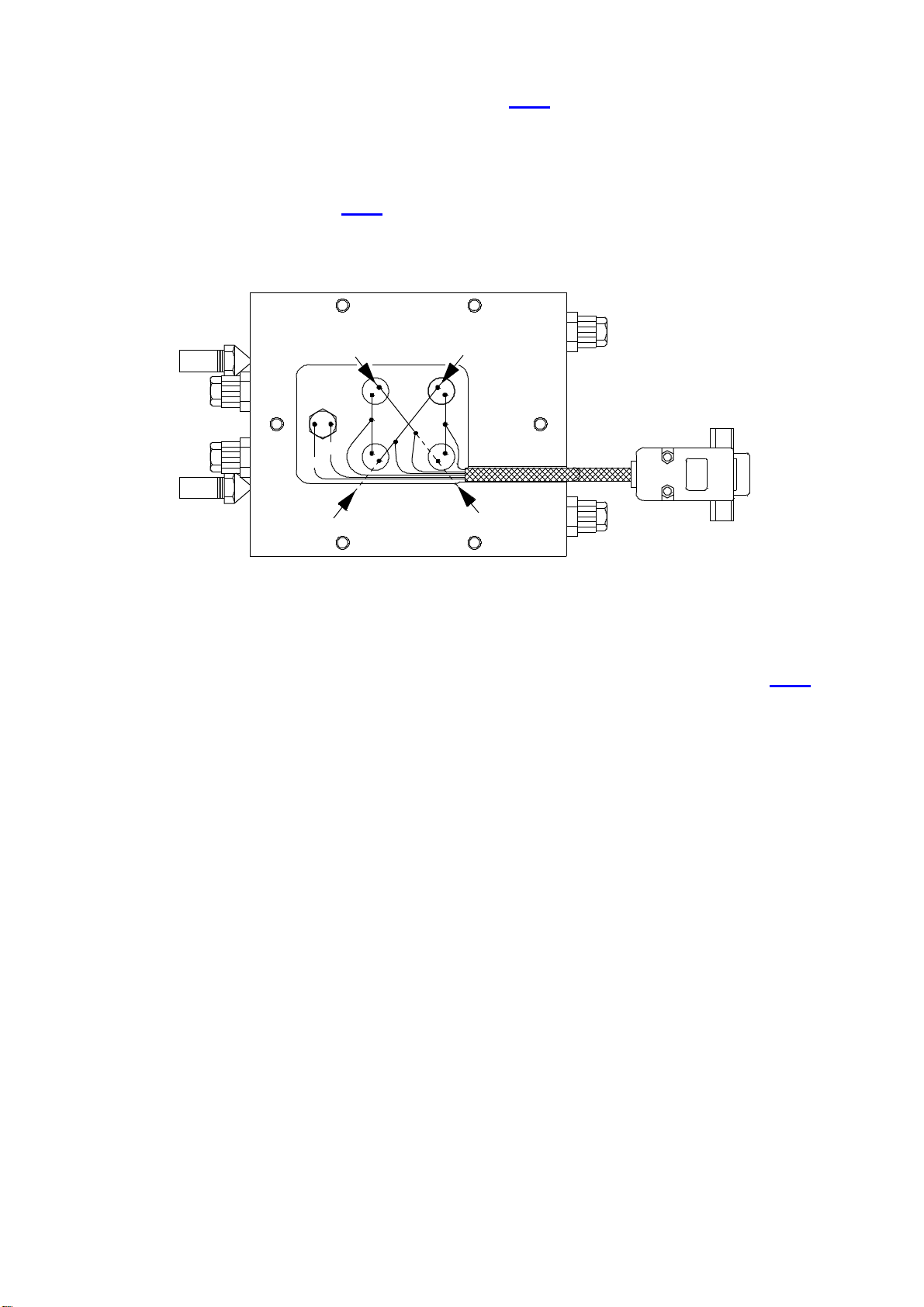
CAUTION :
The thermistor is a small part inside of the glass ball, in the middle of the wire.
br
bl
Pair1
Pair2
Pair1
Pair2
rs
ws ge gn
1-1-3
2002 by ELTRA GmbH Germany – January 2002 – Service Manual OH 900 / ON 900 / ONH 2000
1.2-1
1.2
1.2
No gas flow
C h e ck th e p re s s u re
S e e 4 .2
s
w
itc h . S e e 2 .2
C h e c k th e m a in s p o
w
e r.
h ig he r o r lo
w
e r
?
of the p um p vo lta g e
the re a d in g
Is
O n th e b o ard F C 2 1 .
z e ro
o k o r
?
Is th e
v o lta g e
1 2 V D C
?
th e v o lta g e
Is
R e p la ce th e
flo
w
s e n s o r
R e p la c e th e
b o a rd F C 2 1
A d
j
u s t F C 2 1
S e e 2 .1
R e p la c e th e
b o a rd N R 3 2
A d
j
u s t N R 3 2
S e e 2 .1
Zero
L o
w
e r H ig h e r
Higher
o .k .
Y e s
o .k .
ab ou t 1 2 V D C on T P 4
M e a s u r e a t le a s t
2 0 V D C o n T P 5 ,
?
w
h e n n o flo
w
th a n 0 .6 V D C
on TP1 much higher
o n T P 2 z e ro
o r
Zero
A d
j
u s t th e flo
w
s e e 2 .1
N o
?
ad
j
ustab le
flo
w
Is th e
12VDC
th an 1 0 0
Voltages
C h a n g e th e c h e m ic a ls .
T h e g a s flo
w
is b lo cke d .
S e e 1 .2
T h e p u m p is
w
o rn o u t.
0.6 VDC
1 -6 -E
M e a s u re th e pu m p v o lta g e b e t
w
e e n
T P 1 a n d T P 2 (G N D ) o f th e b o a rd N R 3 2 ,
s e e 2 .1
C h e c k th e o xy g e n p r e s s u re o n th e
fro n t p a n e l g a n g e to b e 1 ,5 ba r (2 2 ps i)
N o g a s fl o
w
o n th e u p p e r flo
w
m e te r
2002 by ELTRA GmbH Germany – January 2002 – Service Manual OH 900 / ON 900 / ONH 2000
1.3-1
1.3
1.3
The flow rate is not stable
Please note: The gas flow in consideration is read on the right-side flow meter.
Vibrations of the ball inside of the flow meter is not a sign of an unstable flow rate. This is
an effect of the weight of the ball and the compressibility of the carrier gas in a small tube.
The flow rate is only unstable, if the average position of the ball becomes higher or lower.
First check the vacuum at the inlet of the electronic flow controller. It should be higher than
50 mbar. If it is not, check the tubes from furnace to flow controller.
If the vacuum is higher than 50 mbar, check the tubes following the flow controller.
Check the complete tubing from the furnace outlet up to the analyser outlet.
Otherwise change the flow controller.
Caution:
It has happened several times already, that the outlet of the furnace was blocked by
silicon grease. Due to an excessive greasing of the surface of the O-ring ( 4 ) of the lower
furnace closure, some of the grease can land onto the furnace outlet hole ( 1 ), causing its
blockage.
In this case open the furnace,
remove the tube ( 2 ) from the furnace outlet ( 1 )
and pass a pipe cleaner ( 3 ) through the
fitting ( 1 ) into the furnace area to
make sure that the hole is
completely free.
3
2
1
1-3
1
4

2002 by ELTRA GmbH Germany – January 2002 – Service Manual OH 900 / ON 900 / ONH 2000
1.4-1
1.4
1.4
The base line of the TC cell cannot be adjusted to zero
The baseline control of the TC-cell is different from the one for the IR-cell.
The values for the "low" and the "high" nitrogen ( or hydrogen, depending on the
instrument ) channels are produced by two different gain stages within one amplifier
connected to the TC detection cell.
The automatic base line control regulates the zero signal of the "high nitrogen" gain stage.
Only the high channel zero value appears on the display .
If the zero value of the "low nitrogen ( hydrogen )" channel is out of range, the electronic
board cannot control this signal to zero. In this case check the "high nitrogen (hydrogen)"
signal with
If the signal of the high channel is higher than ±0.4V, the low channel is out of range.
CAUTION :
Look for the reason of this drift! Adjust the flow rates or the thermostabilization, if
necessary.
If there is no fault, adjust the signal of the "high nitrogen ( hydrogen )" channel to zero
manually, see 2 .12
2002 by ELTRA GmbH Germany – January 2002 – Service Manual OH 900 / ON 900 / ONH 2000
1.5-1
1.5
1.5
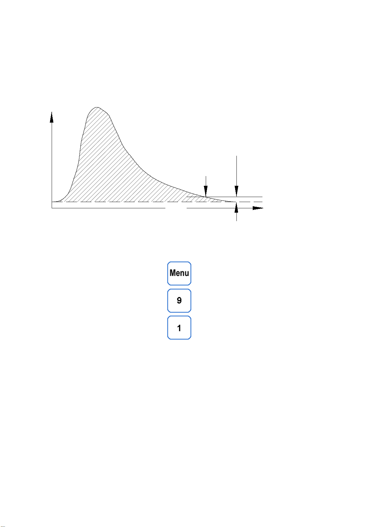
Analysis time too long
The instrument stops the analysis automatically, once the peaks of all activated ranges
have descended to the comparator level, ( see drawing below ).
The comparator level is an artificial zero level which can be adjusted and it is normally just
above the baseline.
If after a preset time, the signal stays higher than the comparator level, the analyser stops
and calculates the result. But this result may be inaccurate, because the peak wasn't
completely recorded.
With
you enter the menu for setting the comparator level.
The standard values for sensitive channels are 250 to 300 for the "low channel",
and 50 to 100 for the "high channel".
Before increasing the values check the following:
Thermostabilisation
Flow rates
Blank value ( a large blank value is a sign for a physical or chemical fault )
Check for gas leakage.
If above functions are OK, it is possible to increase the comparator level by 100 units.
time
Comparator level
Stop
IR output

2002 by ELTRA GmbH Germany – January 2002 – Service Manual OH 900 / ON 900 / ONH 2000
1.6-1
1.6
1.6
High blank value
It is impossible to avoid blank values, because oxygen and nitrogen are contents of the
air. But this blank value should not be higher than 5 to 10ppm.
Otherwise try the following :
Increase the flow rates to 40 / 70 l/h
Fasten the electrodes
Clean the furnace
Use a gas precleaning furnace, filled with copper
Connect a computer to watch the blank value peak and start an analysis without any
sample.
In some cases a small air volume remains in the threads under the lower electrode.
Screw the lower electrode out and fill a small amount graphite powder in. Screw the
electrode in. Repeat this procedure until it needs some force to screw the electrode
complete in.
If the base line of the detectors is unstable due to insufficient mains voltage
( less than 200V AC ), connect a voltage stabilizer ( see 3.14 ).

2002 by ELTRA GmbH Germany – January 2002 – Service Manual OH 900 / ON 900 / ONH 2000
1.7-1
1.7
1.7
Erratic results
The only way to check the repeatability, is to analyse standards. Watch the standard
deviation attested in the certificate of the standards.
Self-made standards are a cheap option to check the calibration in the user’s range.
The following faults cause erratic results :
Insufficient flow rates
Wrong or highly inconsistent blank value of the carrier gas
Damaged electrodes
Bad contact – see 1. 24
Check the electrodes and the flow rates first.
Delete the blank value as follows
Enter the channel number as required
Start analysis
To abort the blank value analysis press
Run five analyses cycles without sample, by entering 1000 mg manually.
The blank value should be 5 to 10 ppm. Otherwise see 1. 6.
Analyse a standard sample 5 times.
The standard deviation should be better than 1% or ± 3 ppm, whichever is higher.
2002 by ELTRA GmbH Germany – January 2002 – Service Manual OH 900 / ON 900 / ONH 2000
1.8-1
1.8
1.8
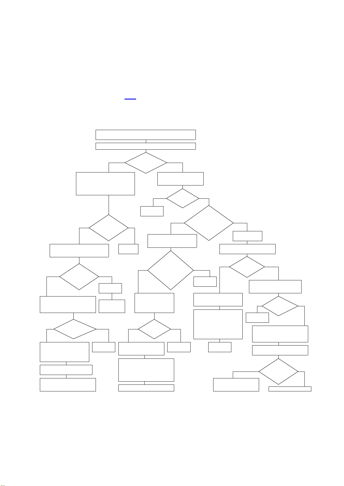
The LED for the temperature regulation of the infrared cell or the
thermoconductivity cell does not flash :
A ) IR - Cell
For detailed explanation, see 2. 5
Is it
higher or
lower than
5.25VDC? Replease
the TH61
Check the DC voltage
between Pin4 and Pin5
of the NR32 see 2.5 Check the
cable
see 1.8
Check the voltage
on the TP1 of NR32
See 2.5
Replace
the NR32
Adjust
see 2.5
Replace the
temperature sensor
200VDC
between Pin
4 and 5
of the NR32?
See 2.5
Replace
the TH61
Check the cable
connecting NR32 to
TH 61. See 1.8
220 VACZERO
Is it
220VAC
or zero?
Measure the AC
supply voltage to
of the NR32 (6-7)
see 2.5
Is it
around 200VDC
or zero?
20 0 VDC
Replace
the NR32
Replace the sensor when
the resistance is lower
than 6 kOhm
Is it
still always
on or off?
The LED of the IR Cell thermostatization
does not flash
YES
ZERO
NO YES
Check the DC voltage
between TP2 and TP1
on the TH 61 see 2.5
NO
Check the DC voltage
between TP2 and TP3
of the TH 61. See 2.5
Adjust around 5.25VDC
See 2.5
Check the cable
connecting NR32 to
TH 61. See 1.8
Check the 13 Pin plug
of the TH61. See 1.8
Remove the plastic cover
and check the cable
connections
Check the wiring see 4.2
Check the 13 Pin plug
of the TH61.
See 1.8
Remove the plastic
cover and check
the cable connections
Is the
voltage on
the capacitor
over 250VDC
or is it almost
zero?
NO
Measure the DC voltage
between TP2 and TP1
of the TH 61. See 2.5
Is
the LED
still always
off ?
200VDC
on the
heaters?
NO YES
Check the voltage of the
heaters see 2.5
The board
NR32 is ok
Is it
higher than
5.25V?
Is the
resistance
much lower than
6 kOhm?
Replace the TH61
NO
Replace
the TH61
Replace
the NR32
Measure the resistance
of the sensor
Check the connection
of the temperature
sensor in the 13 Pin
plug. See 1.8
>2 5 0VDCZERO
LO WER HIGHER
YES
YES
Measure the resistance
of the sensor
Check the connection
of the temperature
sensor in the 13 Pin plug.
See 1.8
Measure the voltage
on the capacitor 100µF
on the NR32 see 2.5
Adjust P1 on the TH61 board see 2.5
z e ro 20 0 VDC
About
200VDC or
zero?
O FF ON
Replace
the NR32
1-14
2002 by ELTRA GmbH Germany – January 2002 – Service Manual OH 900 / ON 900 / ONH 2000
1.8-2
Check that the cable is well connected to the plug, and that there are no short circuits
between the contacts in the 13 pin plug.
Inspect the spring contact ( 2 ) on the connector ( 1 ).
One of the contact threads ( 2 ) could have failed, or one of the connections ( 3 )
could be disconnected.
A look inside the plug ( 4 ) is recommended.
2
3
4
1-14-2
1
rt
sw
sw
123
6
4
3 4 8
ge/gn
ge/gn
swsw
2+15
3+16
25
22
bl
bl
1 5
1
3
5
7
9
10
11
12
1 3
gn
br
Temperature
sensor
200 VDC as long
as the LED is on.
No voltage as long
as the LED is OFF.
Heaters
13 Pin plug.
Remove the
plastic cover
and check the
cable connections.
PRI SEC
vi
sw
sw
rt
rt
vi
*
1-8-3
2 7
blue
brown
yellow
grey
green
orange
pink
red
black
violett
white
bl
br
ge
gr
gn
or
rs
rt
sw
vi
ws

2002 by ELTRA GmbH Germany – January 2002 – Service Manual OH 900 / ON 900 / ONH 2000
1.8-3
B ) TC - Cell
The set point is adjusted with trimmer No.1, turn clockwise to increase the temperature.
If the LED is not flashing 2 minutes after increasing the set point, exchange the cable to
the board TH 61 with the cable to the IR cell.
Check the board TH61 as described for the IR cell.
CAUTION :
The temperature's influence on the baseline of the TC cell is very high. Wait until the
baseline is stable before analysing. Use a computer to check the baseline.
TC CELL
312
2-12
04000
Other manuals for ON-900
1
This manual suits for next models
2
Table of contents
Other ELTRA Measuring Instrument manuals

ELTRA
ELTRA CS-2000 User manual

ELTRA
ELTRA CS-i User manual

ELTRA
ELTRA CS-800 User manual

ELTRA
ELTRA Thermostep TGA User manual

ELTRA
ELTRA ELEMENTRAC CS-i User manual

ELTRA
ELTRA ELEMENTRAC ONHp2 User manual

ELTRA
ELTRA CS-580A User manual

ELTRA
ELTRA CSi/d User manual

ELTRA
ELTRA CS-580A User manual

ELTRA
ELTRA CS-2000 User manual


