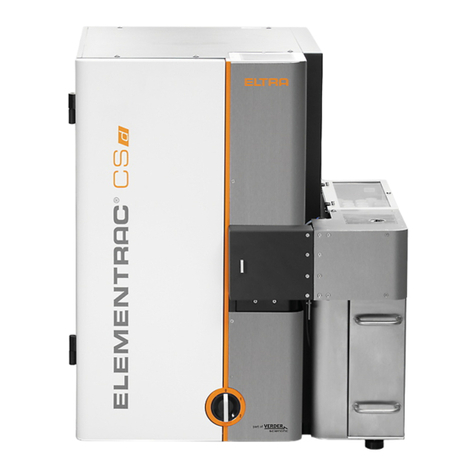
ELTRA CSi/d User manual

© Eltra GmbH, 42781 Haan, Retsch-Allee 1-5, Germany | 24.09.2018 Version 0001
Manual
Autoloader CSi/d
Translation

2
Copyright
© Copyright by
Eltra GmbH
Retsch-Allee 1-5
42781 Haan
Germany

3
Table of Contents
1Contact information .............................................................................................................................. 5
2Notes on the Manual ............................................................................................................................. 5
2.1 Intended use...................................................................................................................................... 5
2.2 Improper use...................................................................................................................................... 5
2.3 Explanations of the Safety Instructions ............................................................................................. 6
2.4 Explanation of the warning symbols.................................................................................................. 7
2.5 General Safety Instructions ............................................................................................................... 7
3General information .............................................................................................................................. 9
3.1 About the device................................................................................................................................ 9
3.2 Transport............................................................................................................................................ 9
4Installation............................................................................................................................................ 10
4.1 Setting up the CSi/d Autoloader ...................................................................................................... 10
4.2 CSi/d Autoloader connections ......................................................................................................... 11
4.3 Dismantling the side cover............................................................................................................... 12
4.4 Switching to manual mode............................................................................................................... 13
4.5 Affixing to the analyzer .................................................................................................................... 14
4.6 Individual step cycles....................................................................................................................... 15
5Operation.............................................................................................................................................. 16
5.1 Operating the CSi/d Autoloader....................................................................................................... 16
5.2 Loading the analyzer ....................................................................................................................... 17
5.3 Moving crucibles.............................................................................................................................. 18
5.4 Disposal of the crucibles.................................................................................................................. 18
6Servicing .............................................................................................................................................. 19
6.1 Dismantling the top and bottom cover............................................................................................. 19
6.2 Adjusting the chain motor belt ......................................................................................................... 21
6.3 Adjusting the chain tension.............................................................................................................. 22
6.4 Adjusting the height of the gripper arm............................................................................................ 24
6.5 Adjusting the gripper arm position................................................................................................... 25
6.6 Adjusting the gripper fingers............................................................................................................ 26
6.7 Speed of Movement......................................................................................................................... 28
7Technical information ......................................................................................................................... 30
7.1 Technical information....................................................................................................................... 30
7.2 Safety circuit .................................................................................................................................... 31
7.3 Non-Stop cycles............................................................................................................................... 32
7.4 Gripper arm positions ...................................................................................................................... 32
7.5 Attaching and removing the plastic pipes........................................................................................ 33
7.6 Error messages ............................................................................................................................... 34
8Disposal................................................................................................................................................ 35
9Index ..................................................................................................................................................... 36

Contact information
4

Contact information
5
1 Contact information
Please contact your local representative in the event of problems. You can find the complete
list of dealers at www.eltra.com.
Of course you can also contact ELTRA-Germany directly:
ELTRA GmbH
Retsch Allee 1-5
42781 Haan
Germany
Web: www.eltra.com
Email: service@eltra.com
2 Notes on the Manual
This Operating Manual provides technical instructions for the safe operation of the device and
contains all necessary information about the topics given in the table of contents. This technical
documentation is meant to be a tutorial and a reference. The individual chapters are self-
contained.
Knowledge of the relevant chapters (for the respective target groups defined according to
areas) is a prerequisite for the safe and correct use of the device.
This Operating Manual contains no repair instructions. In the event of any faults or necessary
repair work, please contact your supplier or Eltra GmbH directly.
Amendments
Subject to technical changes.
Copyright
The forwarding or duplication of this documentation and the recycling and passing on of its
content are only permitted with the explicit consent of Eltra GmbH.
Any infringements of this constitute an obligation to pay damages.
2.1 Intended use
This device is used for the automatic supply of crucibles for the CSi/d analyzer. It may only be
used in the laboratory by appropriately qualified and trained personnel.
2.2 Improper use
Private use and use in conjunction with other equipment than the CSi/d analyzer is not
permitted.
Repairs and modifications may only be carried out by Eltra GmbH, or an authorised
representative, or by qualified service technicians.

Notes on the Manual
6
2.3 Explanations of the Safety Instructions
In this Operating Manual, we give you the following safety warnings
Mortal injury may result from not following these safety warnings. We give you the following
warnings and corresponding content.
DANGER
D1.0000
Type of danger / personal injury
Source of danger
Possible consequences if the dangers are not observed.
Instructions and information on how the dangers are to be avoided.
We also use the following signal word box in the text or in the instructions on action to be taken:
DANGER
Serious injury may result from not following these safety warnings. We give you the following
warnings and corresponding content.
WARNING
W1.0000
Type of danger / personal injury
Source of danger
Possible consequences if the dangers are not observed.
Instructions and information on how the dangers are to be avoided.
We also use the following signal word box in the text or in the instructions on action to be taken:
WARNING
Moderate or mild injury may result from not following these safety warnings. We give you the
following warnings and corresponding content.
CAUTION
C1.0000
Type of danger / personal injury
Source of danger
Possible consequences if the dangers are not observed.
Instructions and information on how the dangers are to be avoided.
We also use the following signal word box in the text or in the instructions on action to be taken:
CAUTION
C2.0000

Notes on the Manual
7
In the event of possible property damage we inform you with the word “Instructions” and the
corresponding content.
NOTICE
N1.0000
Type of property damage
Source of property damage
Possible consequences if the notices are not observed.
Instructions and information on how the property damages are to be
avoided.
We also use the following signal word in the text or in the instructions on action to be taken:
NOTICE
2.4 Explanation of the warning symbols
The warning symbols used are explained below.
Warning of hot surfaces
Warns of hot surfaces. Parts of the device
get hot. Never touch hot components.
Warning of hand injuries
Warns of hand injuries. The device has
moving parts. Never touch moving parts.
For further information, please observe the safety instructions at the relevant places.
2.5 General Safety Instructions
DANGER
D2.0006
Danger caused by burning samples
–Damage to the respiratory tract, skin and/or mucous membranes.
–Radiation damage.
Users themselves must assess the risk emanating from a sample
during analysis.
DANGER
D3.0006
Risk of explosion or fire
Potentially explosive atmosphere
–Due to its design, the device is not suitable for use in a potentially
explosive atmosphere.
The device may not be operated in a potentially explosive
atmosphere.

Notes on the Manual
8
CAUTION
C3.0002
Risk of injury
Lack of knowledge of the Manual
The Manual contains all safety-related information. Disregarding the
Manual can therefore lead to injuries.
Read the Manual carefully before operating the device.
Target group:
All activities required for correct use are described in this Operating Manual. Any activities that
go beyond this may only be performed by authorised electricians who have received in-depth
training for this analyzer.
As the operating company, you must ensure the following with respect to the personnel
instructed to work on the analyzer:
•That all regulations in the area of safety have been noted and understood;
•That, before starting work, they know about all instructions and regulations pertaining to
the target group relevant to them;
•That they have access at all times to technical documentation about this Autoloader;
•That new personnel have been familiarised with the safe, correct use of the Autoloader
before starting work on it, either through verbal instruction by a competent person or with
the help of the technical documentation available.
Incorrect operation can result in personal injury and damage to property. You are responsible
for your own safety and that of your employees.
Ensure that no unauthorised persons have access to the analyzer.
CAUTION
C4.0092
Risk of injury due to modifications
–Modifications to the Autoloader can result in personal injuries.
- Eltra GmbH’s declared conformity with European directives shall then
cease to be valid.
- All warranty claims shall expire.
•Do not perform any modification to the Autoloader and only use
accessories approved by Eltra.
genile
CAUTION
C5.0092
Risk of injury caused by incorrect repairs
–This Manual does not contain any repair instruction.
•For safety reasons, repairs may only be carried out by Eltra GmbH,
an authorised representative or by qualified service technicians.
genile

General information
9
3 General information
3.1 About the device
The CSi/d Autoloader is delivered in an assembled state. Only the connectors need to be
connected on the back and the CSi/d Autoloader screwed to the analyzer. For this reason, no
adjustment is usually required after installation. The various possible settings are, however,
described in detail in the “Servicing” chapter.
3.2 Transport
The CSi/d Autoloader weights 18 kg. It should therefore only be lifted by two people.
When doing so, ensure you grip it securely.
CAUTION
C6.0092
Risk of cuts
–Sheet metal parts can have sharp edges.
•During transport, ensure you grip them securely and do not grip the
underneath of sheet metal parts.
Genn entha

Installation
10
4 Installation
4.1 Setting up the CSi/d Autoloader
Proceed as follows to set up the CSi/d Autoloader:
1.Place the CSi/d Autoloader to the right of the analyzer.
2.When setting up ensure there is a stable, non-slip and fireproof base, and
comply with the following safety instructions in this respect.
The CSi/d Autoloader has now been set up and can be installed.
DANGER
D4.0006
Danger caused by burning samples
–Damage to the respiratory tract, skin and/or mucous membranes.
–Radiation damage.
Users themselves must assess the risk emanating from a sample
during analysis.
WARNING
W2.0021
Fire hazard / risk of burns caused by hot components
Hot components (crucibles, reagents etc.) can fall down
Surfaces onto which the hot component can fall catching fire.
Clothing and other materials catching fire.
Set the Autoloader up in a fireproof environment. Pay special
attention to the desk, floor and other surfaces near the Autoloader.
Always wear suitable work clothes.
Keep the work area free from all materials that could catch fire.
Do not set the Autoloader up in any explosive atmosphere.
CAUTION
C7.0092
Risk of injury caused by the Autoloader falling down
Incorrectly set up or insufficient workspace
–Due to its weight, the Autoloader can cause personal injuries if it falls
down.
•Only operate the Autoloader on a sufficiently large, strong, non-slip
and stable workspace.
•Ensure that the feet of the device are positioned securely.

Installation
11
4.2 CSi/d Autoloader connections
The three connections on the back of the CSi/d Autoloader must be connected to put it into
operation.
Fig. 1: Connections on the back of the CSi/d Autoloader
Number
Component
Description
1
Pneumatic connection
Connection for the pneumatic connection to the
analyzer
2
Electrical connection
Connection for the power supply
3
Analyzer connection
Connection for communication between the
analyzer and CSi/d Autoloader
Proceed as follows to connect the CSi/d Autoloader:
1.With the help of the supplied pneumatic hoses and the tee, connect the
pneumatic connection on the CSi and the CSi/d Autoloader (1) (see Fig. 1:
Connections on the back of the CSi/d Autoloader).
2. Connect the tee to your compressed air supply.
3.Connect the connection inside the analyzer to the analyzer connection (3)
(see Fig. 1: Connections on the back of the CSi/d Autoloader).
4.Connect the power supply unit provided to the electrical connection (2) (see
Fig. 1: Connections on the back of the CSi/d Autoloader).
The CSi/d Autoloader has now been connected.
1
2
3

Installation
12
NOTICE
Damage to the device
The electronics of the device may be damaged.
Only use the power supply unit provided.
4.3 Dismantling the side cover
The side cover must be dismantled to install and adjust the CSi/d Autoloader.
Fig. 2: Side cover
Number
Component
Description
1
Side cover screws
Used to secure the side cover
Proceed as follows to dismantle the side cover:
1.Remove the screws (1) (see Fig. 2: Side cover).
2.Place the side cover to one side.
The side cover has now been removed.
1

Installation
13
4.4 Switching to manual mode
Manual mode can be used to switch through the individual steps of the CSi/d Autoloader.
Fig. 3: Manual mode
Number
Component
Description
1
Button for manual control
Used to switch through the individual steps in
manual mode
2
Electrical connection safety
circuit
If the power supply unit of the CSi/d Autoloader
is plugged in there, the safety circuit is bridged
To switch to manual mode the CSi analyzer must be turned off and connected to the CSi/d
Autoloader. Proceed as follows:
1.Pull the power supply unit from the back of the CSi/d Autoloader.
2.Keep the manual control button (1) pressed and plug the power supply unit
into the designated electrical connection (2) in the safety circuit (see Fig. 3:
Manual mode).
3. Keep the manual control button (1) pressed for a few seconds (see Fig. 3:
Manual mode).
Manual mode has now been activated and the individual steps can be activated using the
manual control button (1).
Switching to manual mode bridges the safety circuit.
Remove the power supply unit to exit manual mode.
1
2

Installation
14
CAUTION
C8.0092
Risk of injury in manual mode
–The safety circuit is deactivated.
•Manual mode should only be used when adjusting the settings on
the CSi/d Autoloader. Important safety devices are deactivated. Exit
manual mode before analysing samples.
Genilellen
4.5 Affixing to the analyzer
Two brackets are used to screw the CSi/d Autoloader to the analyzer.
Fig. 4: Aligning the CSi/d Autoloader
Number
Component
Description
1
Screws for alignment
Used to align the CSi/d Autoloader to the
analyzer
2
Locking screw
Used to lock the alignment
1
2

Installation
15
Proceed as follows to screw the CSi/d Autoloader to the analyzer:
1.Place the CSi/d Autoloader tightly onto the analyzer.
2.Switch to manual mode.
3.Using the manual control button, switch through the individual steps of the
program until the gripper arm has reached the crucible position on the
analyzer (see Chapter 7.4: Gripper arm positions).
4.Align the CSi/d Autoloader so that the gripper arm can place the crucible
midway on the crucible tray of the analyzer.
5.Now align the height of the CSi/d Autoloader by screwing the three
pedestals in and out so that there is a small gap between the crucible and
the crucible tray of the analyzer. With the help of the supplied spirit level,
ensure that the CSi/d Autoloader is horizontal.
6.Using the brackets, screw the CSi/d Autoloader to the analyzer. The CSi/d
Autoloader can be adjusted in a horizontal direction using the slotted holes
on the brackets (1) (see Fig. 4: Aligning the CSi/d Autoloader).
7. Press the locking screw (2) against the brackets and screw it tight. This
prevents the position shifting if you need to disconnect the CSi/d Autoloader
from the analyzer (see Fig. 4: Aligning the CSi/d Autoloader).
The Autoloader has now been connected to the analyzer.
4.6 Individual step cycles
If the CSi/d Autoloader is in manual mode, it is possible to switch through the individual steps of
the device using the manual control button; the CSi/d Autoloader then follows the step
sequence for the analysis mode.
The step sequence follows the pattern below:
1. The crucible chain conveys the first crucible to the chain crucible position (see Chapter 7.4:
gripper arm positions).
2. The gripper fingers move to the analyzer crucible position (see Chapter 7.4: gripper arm
positions).
3. The gripper fingers move to the disposal crucible position (see Chapter 7.4: gripper arm
positions).
Pressing the manual control button again starts the next cycle. We recommend performing
several cycles in manual mode to ensure that the mechanical settings are correct. If not, they
must be adjusted again.

Operation
16
5 Operation
5.1 Operating the CSi/d Autoloader
To start the CSi/d Autoloader in normal operating mode, the device must be connected to the
activated analyzer. The CSi/d Autoloader is switched on at the main switch. It is operated
using the analyzer software, and only the loading of samples to the CSi/d Autoloader takes
place on the device. You can find further information in the software manual for the analyzer.
Fig. 5: CSi/d main switch
Number
Component
Description
1
CSi/d main switch
Switches the device on /off.
Operation of the CSi/d Autoloader
1.Make sure that the CSi/d Autoloader is connected to the activated analyzer.
2.Press the main switch (1) on the CSi/d Autoloader (see Fig. 5: CSi/d main
switch)
The status LED on the main switch of the CSi/d Autoloader lights up and the device has been
switched on.
1

Operation
17
5.2 Loading the analyzer
The CSi/d Autoloader can be loaded with up to 36 samples at the same time.
Fig. 6: Loading the CSi/d Autoloader
Number
Component
Description
1-5
Examples of positions
Order in which the crucibles must be positioned
Proceed as follows to load the CSi/d Autoloader with samples:
1.Place the first crucible onto the crucible tray (1) (see Fig. 6: Loading the
CSi/d Autoloader).
2.Place all further crucibles onto the crucible trays (2-5) etc. (see Fig. 6:
Loading the CSi/d Autoloader).
The CSi/d Autoloader has now been loaded.
5
4
3
2
1

Operation
18
5.3 Moving crucibles
For contamination reasons, crucibles may only be moved before the analysis using crucible
tongs.
DANGER
D5.0006
Danger caused by burning samples
–Damage to the respiratory tract, skin and/or mucous membranes.
–Radiation damage.
Users themselves must assess the risk emanating from a sample
during analysis.
Crucibles are very hot after analysis, and there is a risk of burns. After analysis, crucibles may
only be moved using the crucible tongs.
5.4 Disposal of the crucibles
The crucibles from the analysed samples are collected in a crucible bin to permit their
subsequent disposal.
Fig. 7: Crucible disposal
Number
Component
Description
1
Crucible bin
Bin to collect crucibles after analysis
2
Space for the crucible bin
Space for the crucible bin
The crucibles are automatically collected in the crucible bin (1). Before each analysis process,
make sure there is still enough space in the crucible bin to accommodate the analysed
crucibles. If necessary, empty the crucible bin before starting an analysis process. An analysis
can only be performed if the crucible bin has been put in its designated space (2) (see Fig. 7:
Crucible disposal).
1
2

Servicing
19
6 Servicing
NOTICE
N2.0077
Damage to the housing
Use of organic solvents
Organic solvents can damage coatings.
Organic solvents may not be used to clean the housing.
Only use a slightly moist cloth for cleaning.
6.1 Dismantling the top and bottom cover
Under some circumstances the top cover needs to be removed when servicing the CSi/d
Autoloader.
Fig. 8: Top/bottom cover
1
2

Servicing
20
Fig. 9: Mini XLR connector
Number
Component
Description
1
Top cover screws
Used to secure the top cover
2
Bottom cover screws
Used to secure the bottom cover
3
Mini XLR connector
Connector between the bottom cover and the
analyzer
Proceed as follows to dismantle the top cover:
1.Remove the two screws (1) (see Fig. 8: Top/bottom cover).
2.Pull the top cover forwards and remove it.
The top cover has now been removed.
Under some circumstances the bottom cover needs to be removed when servicing the CSi/d
Autoloader.
Proceed as follows to dismantle the bottom cover:
1.Remove the two screws (2) (see Fig. 8: Top/bottom cover).
2.Release the mini XLR connector (3) (see Fig. 9: Mini XLR connector).
3. Place the bottom cover to one side.
The bottom cover has now been removed.
3
Table of contents
Other ELTRA Measuring Instrument manuals
ELTRA
ELTRA CS-2000 User manual

ELTRA
ELTRA ELEMENTRAC ONHp2 User manual
ELTRA
ELTRA ON-900 User manual
ELTRA
ELTRA CS-580A User manual

ELTRA
ELTRA CS-580A User manual

ELTRA
ELTRA CS-2000 User manual

ELTRA
ELTRA ON-900 User manual
ELTRA
ELTRA ELEMENTRAC CS-i User manual

ELTRA
ELTRA CS-800 User manual
ELTRA
ELTRA Thermostep TGA User manual
