ELTRA CS-800 User manual

© Eltra GmbH, 42781 Haan, Retsch-Allee 1-5, Germany 17.12.2013 0001
Operating Manual
Autoloader CS800/CS2000
Original

2
Copyright
© Copyright by
Eltra GmbH
Haan, Retsch-Allee 1-5
D-42781 Haan
Federal Republic of Germany

3

4
1Operating the machine ..........................................................................................................................5
1.1 General information ........................................................................................................................... 5
1.1.1 Loader models ............................................................................................................................... 5
1.1.2 Space requirements....................................................................................................................... 5
1.1.3 Connecting and disconnecting plastic tubes ................................................................................. 6
1.2 Mechanical connection to the analyzer ............................................................................................. 7
1.3 Chain motor belt adjustment.............................................................................................................. 8
1.4 Chain adjustment............................................................................................................................... 8
1.5 Finger adjustment ............................................................................................................................ 10
1.6 Arm installation ................................................................................................................................ 11
1.7 Electrical and pneumatic connections ............................................................................................. 12
1.8 Up/Down adjustment of the arm ...................................................................................................... 15
1.9 Single step operation for mechanical adjustments .......................................................................... 15
1.10 Vertical laser .................................................................................................................................... 15
1.11 Horizontal laser ................................................................................................................................ 16
1.12 Single step cycles ............................................................................................................................ 18
1.13 Finger position over the pedestal .................................................................................................... 18
1.14 Finger Up/Down speed .................................................................................................................... 18
1.15 Crucible position on the platform ..................................................................................................... 19
1.16 Height of the platform ...................................................................................................................... 19
1.17 Repeating the single step cycle ....................................................................................................... 20
1.18 Non stop cycles ............................................................................................................................... 20
1.19 Error messages ............................................................................................................................... 20
1.20 Final installation after adjusting ....................................................................................................... 21
1.21 Maintenance .................................................................................................................................... 21
1.22 Analysis mode ................................................................................................................................. 21
1.23 Crucibles disposal............................................................................................................................ 22
2Index ......................................................................................................................................................23
Appendix .................................................................................................................................. following page

Operating the machine
5
1 Operating the machine
1.1 General information
The loader is supplied after testing without being completely dismantled. It is only
detached from the analyser and the arm (3) with the fingers (6) (See figure arm
installation) are removed for safety reasons. Therefore, an adjustment after
installation may not be needed however the adjustments are described below.
They may be necessary for accurate readjustment.
1.1.1 Loader models
There are 3 standard loader models available:
130-crucibles version, 104-crucibles version and 36-crucibles version.
The difference between these models is the form of the loader’s platform, i.e. the
size of the loader. There is no difference with regard to loader arm, arm support
and drive, lasers/sensors, chain drive, pneumatics and electronics. Therefore the
adjustments, described in this manual are valid for all models.
1.1.2 Space requirements
Fig. 1: Loader positioning
Keep sufficient space to the right of the analyzer (minimum 86 cm) to place the
loader.
It is suggested to place the analyser in a position where the front end of the
furnace cover (1) aligns with the front end of the desk (2).
NOTICE
Under no conditions should the analyser and loader be placed in direct sunlight or
be exposed to the wind of air conditioners or to the wind blowing through open
windows and doors.
1
2
A

Operating the machine
6
1.1.3 Connecting and disconnecting plastic tubes
To connect the tube, simply push it into the fitting as far as it would go.
Fig. 2: Plastic tube connecting
To disconnect the tube, first press the plastic ring of the fitting up to the metal ring,
keep it properly pressed and pull the tube.
Fig. 3: Plastic tube disconnecting
To reinstall the loader do this:
•The analyzer is switched off (Mains power switch on position 0).
There is no compressed air supply to the analyser.

Operating the machine
7
1.2 Mechanical connection to the analyzer
Fig. 4: Autoloader reinstallation (Top view)
•Before starting reinstallation take a look at the plastic tubes and bear in mind
the way they are supported with the screw (7). Make sure to lay them the
same way during reinstallation.
•Place the loader to the right of the analyzer. The part (1) is the vertical bar
(profile) of the front right corner of the analyzer’s cabinet (top view of cross
section). For further orientation: The round part (2) is the left front foot of the
loader.
•The loader is positioned in a way that the vertical rod (3) is pushed towards
the cabinet so that the cabinet’s corner rod (1) is inside the vertical rod (3).
•The blade (4) is inserted between the rod (3) and the cabinet rod (1).
•The angle rod (5) is installed and fixed with the screws (6).
•Then the screws (7) are fixed so that a solid, stable mechanical connection
between analyzer and loader is made.
1
2
3
5
4
6
7
Front pane l
B

Operating the machine
8
1.3 Chain motor belt adjustment
Fig. 5: Belt tension check
The toothed belt of the chain motor is located underneath the left-hand section of
the loader’s platform. The mechanical tension of the toothed belt (1) can be
checked by applying the force to the belt, as shown on the picture by the red arrow.
If an adjustment is necessary, loose the two screws (2) push the plate (3) to the
back in order to create an appropriate tension of the belt (1) and drive the screws.
After fixing the screws, check the tension of the belt (1) again.
In case of replacing the belt, the adjustment is made the same way.
1.4 Chain adjustment
Fig. 6: Chain tension adjustment
1467-Horizontal laser
3
4
11111
222
D
5
7
6
14647

Operating the machine
9
Fig. 7: Chain tension adjustment (Bottom view)
The loader is supplied with the adjusted chain tension. If necessary, check the
tension of the chain as follows:
•Press and hold several crucible trays (1) of the rear row on the platform so
that they cannot move.
•Move a few trays (2) of the front row to the left and to the right.
They should move for about 1 mm. If not, loose the screw underneath the
toothed wheel (3) and adjust by moving it back and for.
•Fix the screw (3) and check again.
NOTICE
A too strong tension can lead to a blockage when the crucibles are moved by the
motor. If the chain plays too much, bent elements of the chain can block at the
indicated point (4). Therefore keep about 1 mm play as described above.
•Pull the front part (5) for about one or two millimetres.
The turning point is (6). When you release it, it should return back pressing
the crucible tray, which is at pick up position, to the wheel (7) behind the
tray. This is to make sure that each crucible when at pick up position is
always at the same place.
Fig. 8: Autoloader bottom view
14609-Gear motor
14550-Gear wheel
14559-Gear wheel
70500-Belt for drive
2
1
4
3
C
70500
14609
14550
14559
Operating the machine
10
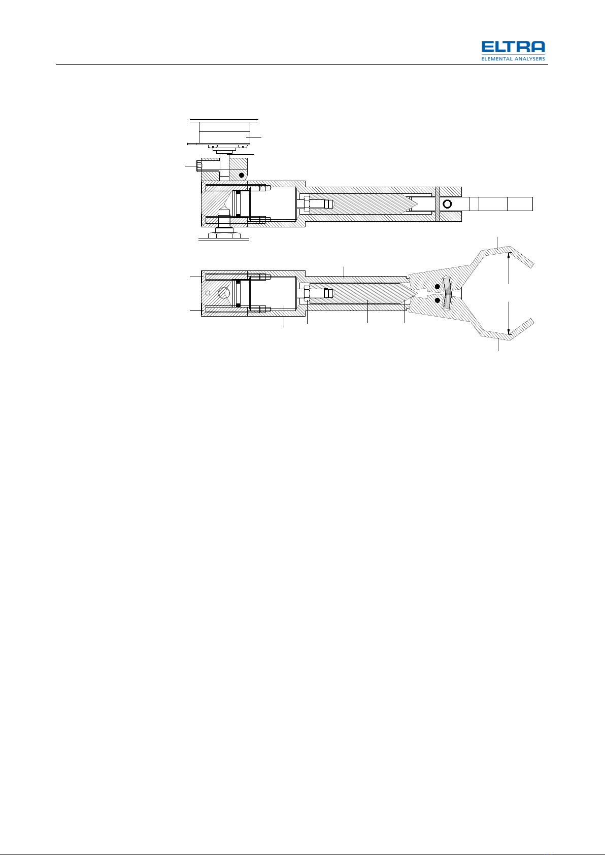
1.5 Finger adjustment
Fig. 9: Finger adjustment
The maximum distance inside the fingers (1) should be about 36 mm.
For adjusting:
•Loose the screw (2).
•Move the assembly (E) down to take it off the shaft (9) of the motor resp. off
the gear box (10).
•Unscrew the four screws (3).
•Remove the piston (4) with the plunger (5).
•Loose the nut (6).
•Screw the plunger (5) to the piston (4) clockwise for making the finger (1)
distance bigger.
•Fix the nut (6) again.
•Unscrew the plunger (5) from the piston (4) (counter clockwise) for reducing
the distance between the fingers (1).
•Fix the nut (6) again.
•Make sure that the plunger (5) is clean.
•Make sure that also the inside surface of the arm (8) is clean from dust,
grease etc.
3
3
57
4
8
29
10
1
1
E
36
6

Operating the machine
11
1.6 Arm installation
Fig. 10: Arm installation
14648-Vertical laser
14795-Finger assembly for Loader CS800/2000
14796 Finger assembly for Loader Helios
14819-Finger motor
•Pass the low end of the spring (8) (see figure pneumatic connections),
through the hole of the cubic support (13) of the arm (3). The upper end of
the spring is already fixed during manufacturing.
•Install the assembly of the arm (3) and the fingers (6) by driving the screw
(17) to fix this assembly on the shaft of the gear motor (14). Handle with care
considering the thin shaft of the gear and the small screw (17) for fixing.
Make sure that the screw will press the flat side of the gear’s shaft.
•Push upwards the plastic tube (15) into the fitting (16).
6
8
1
1
2
2
11
7
5
3
4
F
18
13
16
15
17
10
12
11
10
14648
14795
14796
148 19
9
14

Operating the machine
12
1.7 Electrical and pneumatic connections
Fig. 11: Electrical connection: Motor arm
•Install the 9-pin socket (1)
•Fix with the screws (2).
•Plug in the 9-pin connector (1) of the finger’s motor into the 9-pin socket; see
figure electrical circuit (1).
Fig. 12: Electrical connection: the 25-pin plug
•Locate the electrical cable with a 25-pin plug, coming out of the analyzer.
Plug it in the 25-pin socket, as on the picture above.
1
59
6
Fro nt pane l
1
2
G

Operating the machine
13
Fig. 13: Electrical circuit (14621-6001)
3
4
1
5
6
2

Operating the machine
14
Fig. 14: Pneumatic connections
14016-Sensor holder
14618-Loader board
14795-Finger assembly for Loader CS800/2000
14796-Finger assembly for Loader HELIOS
14819-Finger motor
14820-Finger pneumatic cylinder
60234-Pneumatic valve
60352-Sensor
•Install the magnetic switch (6) at the low end of the pneumatic cylinder as
shown in figure pneumatic connections.
•Connect the 50-pin plug (2) of the loader see figure electrical circuit, to the
50-pin plug (1) on the Loader board.
•Connect the 15-pin plug (5) of the loader; see figure electrical circuit, to the
15-pin plug on the UNI board.
•Connect the compressed air plastic tubes as shown in figure pneumatic
connections.
1
2
4
3
15
Front panel
6
Finger
closing
speed
Arm
up speed
Arm
down speed
8
7
6
14795
14796
60234
14819
14820
14618
60352
14016
I

Operating the machine
15
1.8 Up/Down adjustment of the arm
Fig. 15: Arm installation
•Apply compressed air to the analyzer. The fingers (6) resp. the arm (3) will
go to the UP position.
•Turn the arm (3) manually and position it underneath the wing nut (4).
•Adjust with the screws (9) the height of the arm (3) to be a maximum of only
1 mm underneath the winged nut (4). But even if the arm may touch this nut,
the adjustment is still O.K. The arm will not turn up to the nut (4) when in
operation.
NOTICE
Make sure that the wing nut (4) is properly fixed.
•Check whether the arm (3) is still in proper horizontal position.
•Check and if necessary adjust the position of the fingers (6) to hold the
crucible (7) in coaxial position to the pedestal (8) by readjusting the screws
(9) resp. by moving the arm (3) to the left and to the right and the screws (1)
by moving back and for.
1.9 Single step operation for mechanical adjustments
•Press the adjust button (5) see figure pneumatic connections, and keep it
pressed.
•Turn the mains power switch of the analyzer from position 0 to position 1.
•Release the adjust button immediately after the first beep of the beeper on
the loader’s electronic board.
1.10 Vertical laser
CAUTION
V0075
Eye injury
Laser beam
–Laser beam has high energy and can injure your eyes.
•Don’t look directly into the laser beam.
6
8
1
1
2
2
11
7
5
3
4
F
18
13
16
15
17
10
12
11
10
14648
14795
14796
148 19
9
14

Operating the machine
16
Now the vertical laser (10) for sensing the home position of the arm (3) is
continuously ON. This can be seen by looking at the sensor (11) underneath the
laser (10), see figure arm installation.
If the laser (10) is ON and there is no beeping to hear, it means that the sensor
(11) is sensing the laser beam.
Interrupt the beam between the laser (10) and the sensor (11) to verify the correct
functioning of sensor (11) and beeper.
If the laser (10) is ON and the beeper is beeping, although the beam is not
interrupted, this means that the beam doesn’t hit the sensor (11).The beeper
signalizes this condition. In this case the laser (10) should be mechanically
adjusted so that the beam will be in the middle of the sensor (11). The beeper will
stop beeping.
It is not enough if simply the beeping stops. Make sure that the beam is in the
middle of the sensor.
1.11 Horizontal laser
CAUTION
V0075
Eye injury
Laser beam
–Laser beam has high energy and can injure your eyes.
•Don’t look directly into the laser beam.

Operating the machine
17
Fig. 16: Loader steps
•Press the adjust button (5) of image pneumatic connections again for only
about one second.
Now the horizontal laser (6) for sensing the position of the crucibles (1 to 4) is
continuously ON. This can be seen by looking at the sensor (7) in front of the laser
(6).
CAUTION
Don’t look directly into the laser beam.
If the laser (6) is ON and there is no beeping to hear, it means that the sensor (7) is
sensing the laser beam. For this, make sure that there is no crucible or anything
else between the laser (6) and the sensor (7) preventing the beam from reaching
the sensor (7).
•Interrupt the beam between the laser (6) and the sensor (7) to verify the
correct functioning of detector and beeper.
If the laser (6) is ON and the beeper is beeping, although the beam is not
interrupted, this means that the beam doesn’t hit the detector (7). The beeper
signalises this condition. In this case the laser (6) should be mechanically adjusted
6
7
9
8
1
4
3
J
Home position
Pedestal
Parking
position
Disposal
position
Pickup psition
pick
up
2

Operating the machine
18
so that the beam will be in the middle of the sensor (7). In case of proper
adjustment the beeper will stop beeping.
The adjustment is made by loosing the screws (8) and by turning and moving the
laser (6) until the beeping stops. If necessary, pull up or press down the blade (9)
for vertical adjustment.
NOTICE
It is very essential to adjust the laser for the whole beam to reach the detector. If
you see a part of the beam hitting the aluminium detector housing around the
detector’s hole, readjust until you don’t see any laser radiation on the aluminium
housing.
1.12 Single step cycles
•Place about 10 crucibles into the trays of the chain starting from the left front
tray (1) continuing to the left. (Crucibles 2, 3, 4 etc), see figure loader steps.
•Press the adjust button (5) see image pneumatic connections again for only
approx. one second. This will cause the arm to move to the home position
(vertical laser) and to return back and stay at the parking position.
From now on, after each short pressing of the adjust button, the loader will make
one single step, following the sequence of the steps in analysis mode. The single
step mode gives time for mechanical adjustments.
The sequence of the steps that follow now after each short pressing of the adjust
button (5) of figure pneumatic connections is as follows:
1. The crucibles move so that the first crucible (1) stops at the crucible pick-up
position.
2. The fingers move first to the home position and then to the crucible pick-up
point.
3. The fingers move to the parking position.
4. The fingers (6) move to the position over the pedestal (8), see figure arm
installation.
1.13 Finger position over the pedestal
Now the mechanical adjustment of the position of the fingers (6) can be made.
For better orientation place a crucible (7) on to the pedestal (8). To move the
fingers (6) to the left and to the right, slightly loose the screws (9).The adjustment
of the finger (6) to the direction back and for is done with the screws (1). Take care
to keep the height of the arm (3) as advised before, i.e. about 1 mm underneath to
the wing nut (4).
Fingers down. Now you can adjust the fingers position even more accurately.
1.14 Finger Up/Down speed
The downwards speed of the fingers can be adjusted by the left hand adjustable
restrictor (7) see image pneumatic connections. The upwards speed of the fingers
can be adjusted with the restrictor (8). After adjusting, fix the knurled nuts.
1. Fingers close and take the crucible. If the adjustment of the fingers (6)
position is coaxial to the pedestal (8) resp. to the crucible (7), the crucible will
not move in horizontal direction when the fingers close.
The closing speed of the fingers can be adjusted with the adjustable restrictor (9)
see image pneumatic connections.
2. Fingers up.
3. Fingers turn to the disposal position.
4. The fingers open and the crucible is dropped.

Operating the machine
19
5. The arm goes first to the home position and then it turns back to the pick-up
position
6. Fingers down.
1.15 Crucible position on the platform
Fig. 17: Loader front view
Now the position of the crucible has to be adjusted to be coaxial to the fingers. For
moving the crucible to the left and to the right, slightly loose the screws (1) and (2)
and shift the whole platform (5) accordingly. For moving the platform back and for,
loose the screws (3) and (4).
1. Fingers close. Again, if the crucible doesn’t move when the fingers close, the
crucible is at the right place.
2. Fingers up.
3. Parking position.
1.16 Height of the platform
1. The fingers turn to the pedestal. Check the distance between the top of the
Pedestal and the bottom of the crucible to be 12.5 mm. If it is only approx.
12.5 mm, don’t try to adjust accurately, rather go to the next step.
2. Fingers down. While pressing, watch carefully the crucible. If the height of
the crucibles platform is correct, the crucible should just touch the pedestal.
If the crucible has a distance to the pedestal, the crucibles platform has to be
1
22 4
3
6
7
5
K

Operating the machine
20
lowered by the same distance. If the crucible knocks on the pedestal and the
arm turns up from the horizontal position, the crucibles platform has to be
lifted higher. For moving the platform up and down, loose the screws (1) and
(2) see image autoloader front view. Loose the nut (6) of the foot (7) and turn
the foot by inserting a thin screwdriver or a piece of wire into the hole of the
foot (7). Turn clockwise to lower the platform with the crucible, turn counter
clockwise to move the platform higher. Fix the nut (6) and the screws (1) and
(2).
3. Fingers open.
4. Fingers up.
5. First home and then pick-up position.
6. Parking position.
1.17 Repeating the single step cycle
The next pressing of the adjust button will start the next cycle i.e. the arm will go to
position 1 again. It is advisable to make a couple of cycles with single step to make
sure that the mechanical adjustments described before, are accurate, if not
readjust.
1.18 Non stop cycles
In some cases the automatic repetition of complete cycles is required. For example
in case of a continuous test of the loader by placing 130 empty crucibles for the
loader to run 130 cycles in unattended operation. Also at exhibitions the nonstop
mode without combustion is required. This is obtained by keeping the switch
pressed already before switching on the power, and by keeping it pressed as long
as the cycles have to run.
To do this:
–Place 130 empty crucibles on the loader (or any other required quantity of
crucibles) starting from the left front tray (1) continuing to the left (crucibles 2,
3, 4 etc.) See figure loader steps.
–In order to avoid the need of continuous manual pressing of the button, it
can be mechanically fixed in pressed position before switching on the
analyzer, by mechanically fixing of the button (5) using a rubber ring, see
figure pneumatic connections.
–The analyzer is switched from position 0 to position 1 of the mains power
switch.
–After the last crucible is taken from the platform, the loader will turn the chain
for a while, looking for any more crucibles. If no crucible is found, the chain will
stop turning. The loader electronics will signalize the missing crucibles by triple
beeping. See error messages.
1.19 Error messages
The loader electronic board contains a buzzer for signalizing errors. The number of
beeps in a row specifies the problem according to the table below.
No. of
beeps
Error description
1
The beam of the vertical laser cannot be detected. Defective laser or
detector, dirt in between, arm in between.
2
The beam of the vertical laser is continuously detected. Error of the
finger´s motor.
3
No crucible on the loader although the loader received the command
to load the next crucible.
Other manuals for CS-800
2
This manual suits for next models
1
Table of contents
Other ELTRA Measuring Instrument manuals

ELTRA
ELTRA Thermostep TGA User manual

ELTRA
ELTRA CS-580A User manual

ELTRA
ELTRA ON-900 User manual

ELTRA
ELTRA CSi/d User manual

ELTRA
ELTRA ELEMENTRAC ONHp2 User manual

ELTRA
ELTRA CS-580A User manual

ELTRA
ELTRA CS-i User manual

ELTRA
ELTRA CS-800 User manual

ELTRA
ELTRA CS-2000 User manual

ELTRA
ELTRA ELEMENTRAC CS-i User manual


Popular Measuring Instrument manuals by other brands


Autometers Systems
Autometers Systems IC 995 Installation and operating manual

Sokkia
Sokkia 130R Series Operator's manual

MGP Instruments
MGP Instruments DRM-1 OPERATION & CALIBRATION MANUAL

Sensus
Sensus Dynamic Series quick start guide

Atal
Atal ATD-06 instruction manual

Siemens
Siemens SITRANS MAG 5100W instructions