Elvaco CMe2100 gen.3 User manual

CMe2100 (gen.3/LTE) User’s Manual English– Version 1.1
CMe2100 (gen.3/LTE)
User’s Manual
English
v 1.1

CMe2100 (gen.3/LTE) User’s Manual English
CMe2100 (gen.3/LTE) User’s Manual English
page | 2 (19)
[2021-02]
Version 1.1
Contents
1DOCUMENT NOTES .....................................................................................................4
1.1 COPYRIGHT AND TRADEMARK.........................................................................................4
1.2 CONTACTS..................................................................................................................... 4
2IMPORTANT USAGE AND SAFETY INFORMATION...................................................5
3USING THIS MANUAL ..................................................................................................6
3.1 PURPOSE AND AUDIENCE ............................................................................................... 6
3.2 APPLICABILITY................................................................................................................6
3.3 ONLINE RESOURCES ...................................................................................................... 6
3.4 SYMBOLS.......................................................................................................................6
4INTRODUCTION............................................................................................................7
4.1 PURPOSE....................................................................................................................... 7
4.2 APPLICATION DESCRIPTION.............................................................................................7
4.2.1 Applications................................................................................................................. 7
4.2.2 Convenient setup using the mobile network................................................................ 7
4.2.3 Quick and simple metering with integrated statistics................................................... 7
4.3 PRODUCT FEATURES......................................................................................................8
4.4 COMPATIBILITY AND EXTENSIONS....................................................................................8
4.4.1 Meter compatibility ...................................................................................................... 8
4.4.2 Unit load extension possibilities .................................................................................. 8
4.4.3 Wired and Wireless M-Bus.......................................................................................... 9
5GETTING STARTED....................................................................................................10
5.1 PURPOSE..................................................................................................................... 10
5.2 PRODUCT SPECIFICATION.............................................................................................10
5.3 MOUNT THE DEVICE......................................................................................................11
5.4 INSTALL THE SIM CARD................................................................................................11
5.5 CONNECT THE DEVICE..................................................................................................11
5.5.1 Power supply............................................................................................................. 11
5.5.2 M-Bus terminal.......................................................................................................... 11
5.5.3 Antenna..................................................................................................................... 11
5.5.4 IR interface................................................................................................................ 12
5.5.5 USB master connector.............................................................................................. 12
5.5.6 USB slave connector................................................................................................. 12
5.5.7 Wiring diagram.......................................................................................................... 12
5.6 START UP THE DEVICE.................................................................................................. 12
5.6.1 Start-up...................................................................................................................... 12
5.6.2 Reset to factory default ............................................................................................. 13
5.6.3 LED indications ......................................................................................................... 13
6OPERATIONS GUIDE .................................................................................................14
7TECHNICAL SPECIFICATIONS..................................................................................15
8TYPE APPROVALS.....................................................................................................17
9DOCUMENT HISTORY................................................................................................18
9.1 VERSIONS....................................................................................................................18
9.2 DOCUMENT SOFTWARE AND HARDWARE APPLIANCE...................................................... 18

CMe2100 (gen.3/LTE) User’s Manual English
CMe2100 (gen.3/LTE) User’s Manual English
page | 3 (19)
[2021-02]
Version 1.1
10 REFERENCES.............................................................................................................19
10.1 TERMS AND ABBREVIATIONS .........................................................................................19
10.2 NUMBER REPRESENTATION ..........................................................................................19

CMe2100 (gen.3/LTE) User’s Manual English
CMe2100 (gen.3/LTE) User’s Manual English
page | 4 (19)
[2021-02]
Version 1.1
1 Document notes
All information in this manual, including product data, diagrams, charts, etc. represents information on
products at the time of publication, and is subject to change without prior notice due to product
improvements or other reasons. It is recommended that customers contact Elvaco AB for the latest
product information before purchasing a CMe Series product.
The documentation and product are provided on an “as is” basis only and may contain deficiencies or
inadequacies. Elvaco AB takes no responsibility for damages, liabilities or other losses by using this
product.
1.1 Copyright and trademark
©2021, Elvaco AB. All rights reserved. No part of the contents of this manual may be transmitted or
reproduced in any form by any means without the written permission of Elvaco AB. Printed in Sweden.
CMe Series is a trademark of Elvaco AB, Sweden.
1.2 Contacts
Elvaco AB Headquarter
Kabelgatan 2T
434 37 Kungsbacka
SWEDEN
Phone: +46 300 30250
E-Mail: [email protected]
Elvaco AB Technical Support
Phone: +46 300 434300
E-Mail: support@elvaco.se
Online: http://www.elvaco.com

CMe2100 (gen.3/LTE) User’s Manual English
CMe2100 (gen.3/LTE) User’s Manual English
page | 5 (19)
[2021-02]
Version 1.1
2 Important usage and safety information
The following safety precautions must be observed during all phases of the operation, usage, service or
repair of any CMe Series product. Users of the product are advised to convey the following safety
information to users and operating personnel and to incorporate these guidelines into all manuals
supplied with the product. Failure to comply with these precautions violates safety standards of design,
manufacture and intended use of the product. Elvaco AB assumes no liability for customer’s failure to
comply with these precautions.
CMe2100 receives and transmits radio frequency energy while switched on. Remember that interference
can occur if it is used close to TV sets, radios, computers or inadequately shielded equipment. Follow any
special regulations and always switch off the product wherever forbidden, or when you suspect that it
may cause interference or danger.
CMe2100 operates using the cellular networks. Because of this, connection cannot be guaranteed at all
times under all conditions. Therefore, you should never rely solely upon any wireless product for essential
communications, for example emergency calls. Remember, in order to make or receive calls, the cellular
product must be switched on and be in a service area with adequate cellular signal strength.

CMe2100 (gen.3/LTE) User’s Manual English
CMe2100 (gen.3/LTE) User’s Manual English
page | 6 (19)
[2021-02]
Version 1.1
3 Using this manual
3.1 Purpose and audience
This manual provides all information needed to mount and connect the CMe2100 and is intended for field
engineers and developers.
3.2 Applicability
This manual only applies to CMe2100 gen.3 and CMe2100 LTE. For older versions of the product
manual, please visit http://www.elvaco.com.
3.3 Online resources
To download the latest version of this user’s manual, or to find information in other languages, please
visit http://www.elvaco.com. There, you can also find information about Elvaco’s other products and
services, and how they can help you to achieve successful metering.
3.4 Symbols
The following symbols are used throughout the manual to emphasize important information and useful
tips:
The Note symbol is used to mark information that is important to take into consideration for
safety reasons or to assure correct operation of the M-Bus Metering Gateway
The Tip symbol is used to mark information intended to help you get the most out of your
product. It can for example be used to highlight a possible customization option related to the
current section.
The following symbols are used on the product labels to provide information on how it should be used:
Symbol
Product standard
Description
IEC 60417-5032 (2002-10)
Alternating current.
IEC 60417-5172
Equipment protected throughout by double insulation
or reinforced insulation.
ISO 7000-0434B
Caution, read manual for mounting instructions.
-
Waste electrical products should not be disposed of
with household waste. Please recycle where facilities
exist. Contact your Local Authority for recycling advise.

CMe2100 (gen.3/LTE) User’s Manual English
CMe2100 (gen.3/LTE) User’s Manual English
page | 7 (19)
[2021-02]
Version 1.1
4 Introduction
4.1 Purpose
This chapter provides an initial description of the CMe2100 M-Bus Metering Gateway for Mobile
Networks. In the next-coming sections you will get to know the product applications and how the
CMe2100 can be combined with other products to build versatile solutions.
4.2 Application description
4.2.1 Applications
The CMe2100 is, directly out of the box, a very powerful and versatile M-Bus Metering Gateway.
Applications of the product include:
1. Convenient setup using the mobile network.
2. Quick and simple metering with integrated statistics.
4.2.2 Convenient setup using the mobile network
The CMe2100 is easily installed and configured using the mobile network. By sending text messages via
a cellphone, the Metering Gateway can be setup without having to visit the site. A single SMS command
will have the CMe2100 automatically search the 2-wire M-Bus line and install all meters it is able to find.
The device is thereafter ready to start performing meter readouts and deliver Push Reports to all set
recipients and by any selected protocol.
4.2.3 Quick and simple metering with integrated statistics
Once meters have been installed, the CMe2100 can be configured to perform meter readouts by a
selected time schedule. Meter data is compiled in a suitable report format and delivered to a receiving
system. If the need of integration is low, the report can be as simple as an e-mail sent at a fixed
schedule. However, CMe2100 can also send reports by SMS, upload them to an HTTP server or as
downloadable files to an FTP server.
Thanks to the device’s built-in M-Bus decoder, meter values can be delivered in a human readable format
with correct precision and unit. The built-in database, storing all meter values locally in the CMe2100,
provides a solid base for its system robustness. All Push Reports have intelligent retry mechanisms that
automatically schedules retries for failed reports including all values for which previous transmissions
have failed.

CMe2100 (gen.3/LTE) User’s Manual English
CMe2100 (gen.3/LTE) User’s Manual English
page | 8 (19)
[2021-02]
Version 1.1
4.3 Product features
The CMe2100 has the potential to perform readouts and deliver meter values from all types of M-bus
meters, regardless of manufacturer. This makes the device quick and easy to integrate into an existing
M-Bus system.
Key features of the product include:
•CMe2100 gen.3: An integrated M-Bus Master which can drive up to 8 unit loads, 8T. By using an
M-Bus Master from Elvaco, the number can be extended to up to 128 unit loads, 128T.
•CMe2100 LTE: An integrated M-Bus Master which can drive up to 16 unit loads, 16T. By using
an M-Bus Master from Elvaco, the number can be extended to up to 256 unit loads, 256T
•Customized meter value reports via HTTP, FTP and e-mail.
•Remote configuration of settings using the mobile networks.
For a more extensive technical description of the product, please see chapter 7 (Technical specifications).
4.4 Compatibility and extensions
4.4.1 Meter compatibility
The CMe2100 is compatible with a wide range of meters, including:
•All types of M-Bus meters, regardless of manufacturer.
•The following temperature and humidity sensors, manufactured by Elvaco: CMa10, CMa10W,
CMa11, CMa11W, CMa12W, CMa20, CMa20W.
•All ABB electricity meters equipped with IR interface.
4.4.2 Unit load extension possibilities
The CMe2100 can be used with any M-Bus Master from Elvaco to increase the number of meters it is
able to drive.
CMe2100 gen.3 can by default drive up to 8 unit loads (where one load equals 1.5 mA) and has a
software limit of 128 meters
CMe2100 LTE can by default drive up to 16 unit loads (where one load equals 1.5 mA) and has a
software limit of up to 256 meters (depending of software license).

CMe2100 (gen.3/LTE) User’s Manual English
CMe2100 (gen.3/LTE) User’s Manual English
page | 9 (19)
[2021-02]
Version 1.1
4.4.3 Wired and Wireless M-Bus
The CMe2100 can perform readouts of Wired M-Bus meters, Wireless M-Bus meters, or a combination of
both. To read Wireless M-Bus meters, the Metering Gateway will have to be combined with a Wireless M-
Bus receiver, for example Elvaco’s CMeX50.
All extension devices (Wireless M-Bus Receivers and M-Bus Masters) from Elvaco are
equipped with IR interface to enable communication without any cabling.
Elvaco offers box-build turnkey solutions, containing all necessary products
preconfigured, directly from factory.
CMe2100 (gen.3/LTE) User’s Manual English
CMe2100 (gen.3/LTE) User’s Manual English
page | 10 (19)
[2021-02]
Version 1.1
5 Getting started
5.1 Purpose
This chapter provides instructions on how to get started with the CMe2100. After reading and carefully
following each step of this chapter, the Metering Gateway will be mounted, connected, and started up.
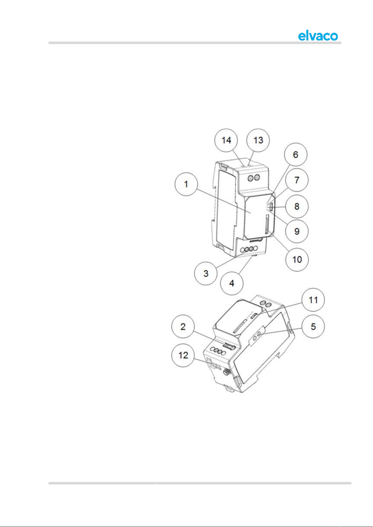
5.2 Product specification
1. Serial number
2. Push button
3. M-Bus terminal
4. Antenna SMA connector
5. IR interface
6. PWR LED, green)
7. ERR LED, red
8. GSM LED, yellow (CMe2100 gen.3)
NET LED, yellow (CMe2100 LTE)
9. STA LED, blue
10. SIM card holder
11. USB slave connector
12. USB master connector
13. Power supply L
14. Power supply N
CMe2100 (gen.3/LTE) User’s Manual English
CMe2100 (gen.3/LTE) User’s Manual English
page | 11 (19)
[2021-02]
Version 1.1
5.3 Mount the device
The CMe2100 is mounted on a DIN rail. The blue clip on the back is used to attach and detach the
device. For safety reasons, A DIN-rail enclosure must cover the terminals.
5.4 Install the SIM card
A SIM card will have to be installed in the CMe2100 for it to use the mobile network. Use a SIM card of
standard size and gently press it into the SIM card holder with the chip facing right. If a prepaid SIM card
is used, make sure that it has enough credit to be able to respond to SMS commands.
The SIM card must have internet access activated for full functionality and should not have
any PIN code activated.
5.5 Connect the device
5.5.1 Power supply
Screw terminal (13) and (14) are used to supply the CMe2100 with power. The main supply voltage
should be in the range of 100-240 VAC, with a frequency of 50/60Hz. Use a cable of cross-sectional area
1.0-1.5 mm2to connect the CMe2100 to the power supply. The power needs to be connected by a clearly
marked and easily accessible switch (IEC 60947-1 and IEC 60947-3) to make sure the device can be
switched off during service work.
The installation shall be performed by a qualified electrician or another professional with the
required knowledge.
The power supply must be protected with a 10 A circuit breaker of characteristics C or slow
blow fuse.
5.5.2 M-Bus terminal
M-Bus is a multi-drop 2-wire M-Bus with no polarity. The M-Bus terminal (3) can be used to connect up to
8 (CMe2100 gen. 3)/16 (CMe2100 LTE) M-Bus meters to the CMe2100. The number can be extended to
up to 128 (CMe2100 gen.3)/256 (CMe2100 LTE) by using an Elvaco M-Bus Extender. Use a cable of
cross-sectional area 0.25-1.5 mm2, for example a standard telephone cable (EKKX 2x2x0.5), to connect
the meters to the M-Bus terminal (3).
All equipment connected to the M-Bus terminal must have doubled or reinforced insulation
from mains to prevent the risk of electric shocks.
Do not exceed the maximum cable length of 1000 m.
5.5.3 Antenna
CMe2100 gen.3: Connect the included stub antenna to the SMA connector (4). If the device is mounted
inside of a metal cabinet or if the signal strength is insufficient (3 or less), an external antenna should be
used. Please visit http://www.elvaco.com/ to find a suitable antenna option that can increase the mobile
network coverage.
CMe2100 LTE: CMe2100 LTE needs to be connected to an external antenna, which is not included.
Please visit http://www.elvaco.com/ to find a suitable antenna option for mobile network coverage.

CMe2100 (gen.3/LTE) User’s Manual English
CMe2100 (gen.3/LTE) User’s Manual English
page | 12 (19)
[2021-02]
Version 1.1
5.5.4 IR interface
By using the IR interface, CMe2100 can communicate with Elvaco M-Bus Masters and Wireless M-Bus
Receivers (CMeX Series) as well as ABB electricity meters without using any cables. Mount the
CMe2100 next to the other device with the IR interfaces of the two products facing each other. Before
attempting to use the IR interface, make sure to remove the IR shield (5).
5.5.5 USB master connector
CMe2100 is equipped with a USB master port, which will be used for upcoming product features.
It is important that the USB master connector is NOT used to connect the CMe2100 to a
computer. For that purpose, use the USB slave connector.
All equipment connected to the USB port must have doubled or reinforced insulation from
mains to prevent the risk of electric shocks.
5.5.6 USB slave connector
CMe2100 is equipped with a USB slave port, which will be used for upcoming product features.
5.5.7 Wiring diagram
5.6 Start up the device
5.6.1 Start-up
On successful connection of power, the CMe2100 will be ready to use after undergoing a booting session
of approximately 30 seconds to one minute.

CMe2100 (gen.3/LTE) User’s Manual English
CMe2100 (gen.3/LTE) User’s Manual English
page | 13 (19)
[2021-02]
Version 1.1
5.6.2 Reset to factory default
In order to reset the product configurations to factory default, press and hold the push button (2). The
CMe2100 will restart and the settings will be reset to factory default. The reset can also be performed
remotely by sending the command Factoryreset to the phone number of the SIM card installed in the
Metering Gateway.
5.6.3 LED indications
The product is equipped with four different LED lights. Table 1-4 below provides an explanation of each
LED indication.
Green LED
Red LED
Product state
Visual
Permanently off
Permanently off
Power off or performing restart.
Permanently on
Permanently on
Power on.
1500 ms on /
100 ms off
Permanently off
Normal operation.
1500 ms on /
100 ms off
Permanently on
Short circuit or overcurrent on
M-Bus.
1500 ms on /
100 ms off
800 ms on /
800 ms off
No SIM card installed.
1500 ms on /
100 ms off
100 ms on /
1500 ms off
Not connected to network.
Table 1: Green and red LED indications
Yellow LED
Product state
Visual
Permanently off
Power off or ongoing restart
500 ms on / 500 ms off
Limited network service due to one of the
following reasons:
•No SIM card installed.
•PIN code error.
•Network search in progress.
10 ms on / 990 ms off
(Only for CMe2100 gen. 3)
GSM CS data call or GSM voice call in
progress or established.
10 ms on / 1990 ms off
Ongoing data transfer.
10 ms on / 3990 ms off
Product registered on a network and no
ongoing data transfer.
Table 2: Yellow LED
Blue LED
Product state
Visual
Permanently off
Upcoming features.
Table 3: Blue LED

CMe2100 (gen.3/LTE) User’s Manual English
CMe2100 (gen.3/LTE) User’s Manual English
page | 15 (19)
[2021-02]
Version 1.1
7 Technical specifications
Type
Value
Unit
Comments
Mechanics
Casing material
Polyamide
-
Protection class
IP20
-
Dimensions (w x h x d)
36 x 100 x 65
mm
2 DIN modules
Weight
120
g
Mounting
DIN-rail
-
DIN 50022, 35 mm
Antenna
SMA female
-
SIM card
Push-push type
-
Electrical connections
Supply voltage
Screw terminal
-
Cable 1.0-1.5 mm2, 0.5 Nm tightening
torque
M-Bus master port
Screw terminal
-
Cable 0.5-1.5 mm2, 0.5 Nm tightening
torque
USB master port
Type A
-
USB slave port
Type micro B
-
Network
Mobile
-
Radio
Electrical characteristics
Nominal voltage
100-240
VAC
+/- 10%
Frequency
50/60
Hz
Power consumption (max)
<6
W
Power consumption (nom)
<1
W
Installation category
CAT 3
-
Environmental specifications
Operating temperature
-20 to +55
°C
Operating humidity max
80 % RH at
temperatures up to
31 °C, decreasing
linearly to 50 % RH
at 55 °C
-
Operating altitude
0-2000
m
Pollution degree
Degree 2
-
Usage environment
Indoors
-
Can be extended with IP67 enclosure
for outdoor use
Storage temperature
-40 to +85
°C
User interface
Green LED
Power
-
Red LED
Error
-
Yellow LED
Network status
-
Blue LED
Permanently off
(Upcoming features)
-

CMe2100 (gen.3/LTE) User’s Manual English
CMe2100 (gen.3/LTE) User’s Manual English
page | 16 (19)
[2021-02]
Version 1.1
Push button
Factory reset
-
Configuration
SMS, HTTP, GSM
CSD, Telnet
-
M-Bus
Interfaces
IR, integrated M-
Bus Master
-
Maximum number of M-Bus
devices (software limit)
128 (CMe2100
gen.3)/256
(CMe2100 LTE)
-
Transparent M-Bus
GSM and TCP/IP
-
Software limit does not apply to
Transparent M-Bus mode
Decryption
No
-
Integrated M-Bus Master
M-Bus standard
EN 13757
-
Full M-Bus decoder implemented
M-Bus baud rate
2400 and 9600
Bit/s
Nominal voltage
28
VDC
Maximum unit loads
8/12
T/mA
Can be extended with CMeX10-13S
Series
M-Bus search modes
Primary, secondary
-
Maximum cable length
1000
m
100 nF/km, maximum 90 Ω
General
Real time clock backup
12
h
Real time clock accuracy
<2
s/day
Script engine
Intelligent script
engine for active
content generation
-
Software/firmware update
HTTP
-
Measurement reports
HTTP, FTP, SMTP
(e-mail), SMS
-
Data storage (examples)
15 minute values
Meters Days
1 200
32 6
64 3
128 1
-
Hourly values
Meters Days
1 800
32 25
64 12
128 6
-
Mobile network
GPRS class
Up to 12
-
Band
850/900/1800/1900
MHz

CMe2100 (gen.3/LTE) User’s Manual English
CMe2100 (gen.3/LTE) User’s Manual English
page | 17 (19)
[2021-02]
Version 1.1
8 Type approvals
Approval
Description
EMC
EN 61000-6-2, EN 61000-6-3, EN 301 489-1, EN 301 489-7
Safety
EN 61010-1, CAT 3
CMe2100 (gen.3/LTE) User’s Manual English
CMe2100 (gen.3/LTE) User’s Manual English
page | 18 (19)
[2021-02]
Version 1.1
9 Document history
9.1 Versions
Version
Date
Description
Author
1.0
2020-04
First version (merged)
David Svensson
1.1
2021-02
Updated version for software 3.2.5
David Svensson
9.2 Document software and hardware appliance
Type
Version
Date
Comments
Hardware
Rev 1B
Software
3.2.5

CMe2100 (gen.3/LTE) User’s Manual English
CMe2100 (gen.3/LTE) User’s Manual English
page | 19 (19)
[2021-02]
Version 1.1
10 References
10.1 Terms and abbreviations
•List all abbreviations used in the manual and what they represent.
Abbreviation
Description
PDP
Packet Data Protocol
10.2 Number representation
•Decimal numbers are represented as normal number, i.e. 10 (ten).
•Hexadecimal numbers are represented with prefix 0x, i.e. 0x0A (ten)
•Binary numbers are represented with prefix 0b, i.e. 0b00001010 (ten)
This manual suits for next models
2
Table of contents
Other Elvaco Measuring Instrument manuals

Elvaco
Elvaco CMi6140 User manual

Elvaco
Elvaco CMi4110 User manual

Elvaco
Elvaco CMeX20w User manual

Elvaco
Elvaco CMe3100 User manual

Elvaco
Elvaco CMi6140 User manual

Elvaco
Elvaco CMi4130 User manual

Elvaco
Elvaco CMi6110 User manual

Elvaco
Elvaco CMi6140 User manual

Elvaco
Elvaco CMi4110 User manual

Elvaco
Elvaco CMi4170 User manual


