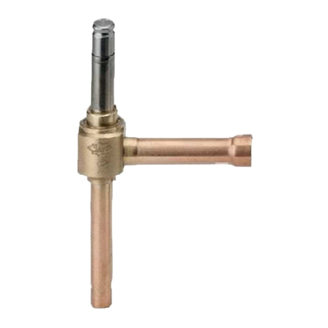
83000 Valve
Instruction Manual
October 2010
5
Tighten the bonnet with a wrench until there is
metaltometal contact.
3. Insert the plunger (key 10) and push it in and out.
The piston subassembly (key 3) should travel easily
up and down.
Valve Body to Bonnet Assembly
1. Place the diaphragm (key 5) in the bonnet yoke
(key 2) cavity.
2. Place the Oring (key 15) on the diaphragm (key
5) in the cavity. This should hold the diaphragm in
place while assembling.
3. Place the bonnet assembly onto the valve body
(key 1).
4. The locking screw (key 13) will thread through the
bonnet yoke (key 2) and tighten into the valve body
(key 1).
Calibration
1. Reassemble the valve by inserting the Oring
(key 15) and diaphragm (key 5) into the valve body.
2. Replace the bonnet yoke assembly (key 2) and
install the bolts (key 13) and tighten. Add the jam nut
(key 27) and travel indicator disk (key 58) to the
plunger (key 10). Place the drive nut (key 9) over the
plunger (key 10). Line up the plunger (key 10) in the
bearing cartridge assembly (key 4). Screw the
actuator onto the plunger (key 10) until the actuator
yoke touches the bonnet (key 8). Lock the actuator
with the drive nut (key 9).
Do Not Attempt to Rotate the Plunger
(key 10)
CAUTION
To prevent damage to the plunger (key
10) or bearing cartridge subassembly
(key 4), be sure the hex jam nut (key
27) is not tightened against the travel
indicator (key 58).
1. For an airtoretract actuator (airtoopen/fail
closed). Apply 6.9 bar (100 psi) air pressure (or N2)
to the normal valve inlet A. Apply 0.2 bar (3.2 psi) air
signal to the actuator. Add 0.07 bar (1 psi) signal to
the actuator if the inlet pressure exceeds 6.9 bar
(100 psi). If the valve leaks, slowly turn the actuator
stem counterclockwise. This will move the plunger
(key 10) down until leakage is below 1 cc/min. Lock
the plunger (key 10) in position with the jam nut (key
27). Calibrate the travel scale and check for 12.7
mm (1/2 inch) valve travel; apply a 1.04 bar (15 psi)
signal. Reverse the signal; the plunger should move
in the opposite direction with less than 0.014 bar (0.2
psi) signal change.
2. For an airtoextend actuator (airtoclose/fail
open), use the same procedure as in step one,
except apply 0.88 bar (12.8 psi) to the actuator to
calibrate the shut off position.
Note
For Baumann 16 actuator ONLY. For
inlet pressures exceeding 10.6 bar (150
psi), 12.77 mm (NPS 1/2) or 20.7 bar
(300 psi), 6.35 mm (NPS 1/4), use a
positioner or I/P transducer with an
output pressure of 0.07 1.2 bar (117
psi)(ASMEFCI Standard 872) to
ensure the valve will close properly.
Parts Ordering
When corresponding with your Emerson Process
Management sales office about this equipment,
always mention the valve serial number. When
ordering replacement parts, also specify the key
number, part name, and desired material using the
following parts tables.
WARNING
Use only genuine Fisherrreplacement
parts. Components that are not
supplied by Emerson Process
Management should not, under any
circumstances, be used in any Fisher
valve, because they may void your
warranty, might adversely affect the
performance of the valve, and could
cause personal injury and property
damage.
Note
Neither Emerson, Emerson Process
Management, nor any of their affiliated
entities assumes responsibility for the
selection, use, or maintenance of any
product. Responsibility for the
selection, use, and maintenance of any
product remains with the purchaser
and end user.
