manuals.online logo
Brands
  1. Home
  2. •
  3. Brands
  4. •
  5. Emerson
  6. •
  7. Control Unit
  8. •
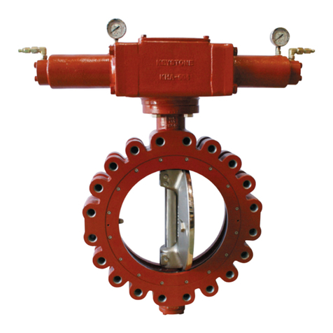
  9. Emerson Keystone Figure 320 User manual

Emerson Keystone Figure 320 User manual

KEYSTONE COMPOSEAL BUTTERFLY VALVES, WAFER STYLE
InstallatIon and MaIntenance InstructIons
1 STORAGE AND HANDLING
1.1 PROTECTION
Keystone butterfly valves are delivered with
protection in accordance with the Keystone
Engineering Instructions, to protect the valve
from damage. Wrapping and/or covers should
be left in place until installation of the valve.
1.2 STORAGE
When valves are to be stored for some time
(2 months or more) before being fitted, storage
should be in the original delivery crates or
cases.
1.2.1 Storage conditions
The valves should be stored off the ground in a
clean, dry indoor area.
Protect the valve from temperature and
humidity extremes, and exposure to excessive
dust, moisture, vibration, deformations,
sunlight and ozone.
INTENDED VALVE USE
The valve is intended to be used only in
applications within the pressure/temperature
limits indicated in the P/T diagram of the
product manual.
The CompoSeal wafer butterfly valve is
designed for wafer use only. No dead end
service!
Ensure that valve materials are compatible with
the pipeline fluid. 1.3 HANDLING
To prevent damage during handling, the valves
should be lifted by hand or using appropriate
lifting equipment. The valves should be
protected from external events e.g. bumps,
hitting and vibrations during transport. Any
flange protection needs to be removed before
the valve is mounted in the pipeline. Lift the
valve with great care from the transport
package (crate, pallet). While handling or
installing the valve, ensure that no damage
occurs to the valve, the pneumatic/electrical or
hydraulic actuator or other instruments.
Please read these instructions carefully
2 INSTALLATION
WARNING
For safety reasons it is important to take the
following precautions before starting to work on
the valve:
1.
Personnel making any adjustment to the valves
should utilize suitable equipment. All required
personal protection means should be worn.
2. The line must be depressurized before
installing the valve.
3. Installation and handling of the valves should
only be done by personnel that is trained in all
aspects of manual and mechanical handling
techniques.
4. Misuse of the valve is not allowed. The valve,
handles, actuators and other parts may not be
used as ‘climbing tools’.
5. Ensure that valve pressure/temperature
limitations marked on the valves tag plate
are within the service conditions. The trim
number on the valves tag plate identifies
the valve materials. See Product Manual for
valve specific P/T diagram and trim number
definition.
6. Ensure that valve materials are compatible
with the pipeline fluid.
2.1 VISUAL VALVE INSPECTION
1. Confirm that the materials of construction
listed on the valve are appropriate for the
service intended and are as specified.
2. Check if valve and actuator are not damaged
during transport or handling.
VCIOM-00786-US 14/09
IMPORTANT
Before valves are being installed or used the
following actions are recommended.
1. Valves/parts have to be inspected and
thoroughly cleaned if required.
2. Rubber parts need to be greased with silicone
grease if not present anymore.
3. All surfaces in contact with seats have to be
thoroughly cleaned and greased with silicone
grease if stored for more than 5 months.
Recommendations
1. Temperature: storage temperature below
77°F, above 32°F preferable below 60°F.
2. Humidity: storage conditions should be such
that condensation does not occur, store in
a dry environment. Maximal 50% relative
humidity.
3. Light: valve rubbers should be protected
from light, in particular direct sunlight or
strong artificial light with high ultra violet.
4. Ozone: storage rooms should not
contain any equipment generating ozone.
E.g. lamps, electric motors.
Emerson.com/FinalControl © 2017 Emerson. All rights reserved.
2
YY
Q
KEYSTONE COMPOSEAL BUTTERFLY VALVES, WAFER STYLE
InstallatIon and MaIntenance InstructIons
Notes
- The valve can be installed in the pipeline
either with or without the actuator mounted
on top of the valve. Make sure you are able
to turn the disc carefully to a more closed/
open position to prevent the disc edge
from touching the adjacent flanges while
positioning the valve.
- It is the responsibility of the valve user - and
not the valve manufacturer - to ensure
that the pipeline system has been built
professionally and the valve has been
properly installed.
- Adjacent piping must be positioned so that
minimal piping stresses are transmitted to
the valve flanges during or after installation.
- Handling and lifting of the valves during
installation must be performed following the
same instructions described in the previous
paragraph ‘1.3 Handling’.
- If an actuator or handle (especially the
composite handle) is to be mounted on the
valve, apply a little bit of grease to the shaft
to ensure easy assembly. Avoid hammering
or hitting on the handle or actuator during
assembling at all times.
- Remove the 4 snap-off nibs for installing the
valve between AS2129 E flanges NPS 3 only
(Fig. 2).
Fig. 1
2.2 FLANGE AND PIPE COMPATIBILITY
Check matching of flange drilling pattern of
valve and pipe flange before assembly.
Flanges have to meet the following
requirements (Fig. 1):
- The face inside diameter should be:
D min: The valve Q dimension + adequate
disc clearance.
D max: The optimum inside diameter (ID)
is equal to the inside diameter of flange
standard EN 1092-1, table 8, type 11. For
larger than D max inside diameters or
other flange types please contact your local
Emerson Sales organization, as larger inside
diameters might result in reduced valve
functionality.
- If the flange or pipe is provided with a raised
face, the diameter of this shall be at least
⅜” larger than the YY-dimension of the
valve.
The O-ring design of the Keystone CompoSeal
eliminates the need for gaskets. If for some
reason required, flange gaskets can also
be used. When flange gaskets are used
(min. 0.04" / max 0.08” thick rubber gaskets are
recommended) the O-rings must be removed
from the body.Use flange bolting in accordance
with the appropriate standard.
Dmax/min
Do not use the valve as a crow-bar to spread
the flanges, this might lead to damage to
the flange area and/or damage to the O-ring
sealing.
2.3 VALVE INSTALLATION
The valves are bi-directional and can be fitted
in either direction relative to the flow. The valve
will control flow equally in either direction. The
recommended installation position is shaft
horizontal and the lower discedge opening
downstream (especially for slurry service and
media with a tendency for sedimentation).
For optimum valve control and smooth
performance, it is recommended to have 10 to
20 pipe diameters of straight run inlet piping
and 3 to 5 pipe diameters straight outlet piping.
IMPORTANT
Mating flange faces should be in good condition
and free of dirt and/or inclusions.
Both pipe insides must be well cleaned before
installing the valve.
2.3.1 Existing system
1. Check whether the flange distance meets
the valve face-to-face dimensions. Spread
the flanges with adequate tooling for easy
insertion of the valve.
2. Close the valve so far, that the disc edge is
at least ½” within the body flanges.
3. Insert the valve between the flanges, pay
extra attention to the flange sealing O-rings.
Adequate flange spreading is required to
prevent the O-rings from rolling out of its
groove. Place 2 two flange bolts trough the
pipe flanges and the locating lugs of the
valve to support the valve.
4. Check if the flange sealing O-rings are still
in place.
5. Center the valve body and insert all flange
bolts. Tighten the flange bolts hand tight.
6. Slowly open the valve completely. The disc is
in line with parallel flats.
7. Maintain the valve flange alignment while
gradually removing the flange-spreaders
and tighten the flange bolts hand tight.
8. Slowly close and open the valve to check for
adequate disc clearance.
9.
Cross tighten all the bolts with the
recommended bolt torque shown in Table
1. Do not exceed the maximum bolting
torques, as this can lead to overloading of the
composite body!
Fig. 2
3
1.5 130/450/550 180/500/625 180/500/625 130/450/550
2130/450/550 180/500/625 180/500/625 180/500/625
2.5 180/500/625 270/800/975 270/800/975 270/800//975
3270/800/975 180/500/625 180/500/625 270/800/975
4350/1100/1400 270/800/975 270/800/975 270/800/975
5350/1100/1400 350/1100/1400 350/1100/1400 350/1100/1400
6350/1100/1400 450/1500/1800 450/1500/1800 450/1500/1800
8450/1500/1800 550/2125/2650 450/1500/1800 550/2125/2650
10 450/1500/1800 550/2125/2650 625/2125/2650 625/2125/2650
12 550/1500/1800 625/2125/2650 700/2125/2650 700/2125/2650
KEYSTONE COMPOSEAL BUTTERFLY VALVES, WAFER STYLE
InstallatIon and MaIntenance InstructIons
TABLE 1
Size Minimum / Recommended / Maximum flange bolt torque [lbs in]
[NPS] PN 6 PN 10 PN 16 ASME 150
NOTES
Bolt specifications: minimum class 8.8, coarse thread, friction thread and nut-flange friction: 0.14
2.3.2 New system
1. With the disc in near-closed position, center
each mating flange with the valve body. Fix
the body with some flange bolts and tighten
the bolts (do not exceed the maximum
tightening moments, see table 1).
2. Use the flange-valve-flange assembly for
fit-up and centering to the pipe.
3. Tack-weld the flanges to the pipe.
4. Remove the bolting and remove the valve
from between the flanges.
5. Finish-weld the flanges to the pipe and
allow the flanges to cool completely.
6. Install the valve according the procedure for
installing in the existing system.
IMPORTANT
Do not finish-weld the flanges to the pipe with the
valve bolted between the flanges as this will result
in serious heat-damage to the composite body
and the flange sealing rubber O-ring.
2.6 TROUBLESHOOTING GUIDE
Symptom Possible cause Resolution
Valve would not rotate Actuator has failed Replace or repair
Valve packed with debris Flush or clean valve to remove debris
Valve leaking Valve not fully closed Close valve
Debris trapped in valve Cycle and flush (with valve open) to remove debris
Seat is damaged Replace valve
Jerky operation Debris trapped in valve Cycle and flush (with valve open) to remove debris
Air supply actuator inadequate Increase air supply pressure and/or volume
2.4 VALVE VERIFICATION
Check the operation of the valve by operating it
from ‘fully open’ to ‘completely closed’ position.
To verify the valve operation, the disc position
indicator on the actuator or the handle should
rotate between the ‘fully open’ and ‘completely
closed’ indicators on the actuator or throttling
plate. Generally the valve disc travels clockwise
to close.
2.5 SOURCES OF POSSIBLE DANGER
2.5.1 Mechanical
When manual operators are used, available
space should be checked to prevent the risk of
jamming hands.
IMPORTANT
Use pliers to snap-off the nibs and wear eye
protection to prevent hand and eye injuries.
2.5.2 Electrical
The composite material can be electro
statically charged by a fluid passing on the in-
and/or outside of the valve. When discharging
a spark might rise. Behavior of the valve is not
different from plastic piping.
2.5.3 Thermal
A) If the valve is used in applications with a
fluid temperature greater than 104ºF or
less than -4°F precautions should be taken
to prevent injury from touching the valve
outer surface. Also, the handle or operator
of the valve might be extreme hot or cold.
Personnel should use proper personal
protection equipment to prevent injuries.
For example: protection gloves.
B) Hot surfaces can be a potential source of
ignition of the environment.
2.5.4 Operational
A) Closing a valve too fast may result in
water hammer in the upstream part of the
pipeline. Water hammer results in excessive
stresses in the valve and will cause severe
damage. Water hammer should be avoided
in all circumstances.
B) A fluid passing the disc of a butterfly
valve has the tendency to close the valve
disc. Take care when unlatching the valve
operating mechanism.
4
KEYSTONE COMPOSEAL BUTTERFLY VALVES, WAFER STYLE
InstallatIon and MaIntenance InstructIons
3 MAINTENANCE
The Keystone CompoSeal is designed to require
a minimum of maintenance.
WARNING
Depressurize and, if necessary in case of
dangerous fluids, drain the line and flush with
appropriate cleaning fluid before starting any
maintenance. Failure to do so may cause serious
personal injury and/or equipment damage.
Before disassembling the valve, ensure the valve
has been decontaminated correctly from any
harmful gasses or liquids and that it is within a
safe temperature range for handling. Personnel
making any adjustments to the valves should
utilize suitable equipment. All required personal
protection means should be worn. Only personnel
trained in all aspects of manual and mechanical
handling techniques must carry out handling of
the valves.
3.1 ROUTINE MAINTENANCE
Routine maintenance or lubrication is not
required other than periodic inspection to
ensure satisfactory operation and sealing.
3.2 REMOVING THE VALVE
1. Turn the disc to nearly closed position.
(The disc is in line with the parallel flats).
2. Loosen all flange bolts and remove the
bolts.
3. Spread the flanges with adequate tooling,
and remove the valve.
3.3 VALVE DISASSEMBLY
Disassembly is not possible. The body halves
are fixed by a one way connection.
Parts identification
1Body
2Disc stem
3Seat
4O-ring
COMPOSEAL WAFER
Parallel flats
Flange locating holes
Mounting holes
Top view
© 2017 Emerson. All rights reserved.

This manual suits for next models

1

Other Emerson Control Unit manuals

Emerson Fisher Large ED User manual

Emerson

Emerson Fisher Large ED User manual

Emerson Keystone PED Quick guide

Emerson

Emerson Keystone PED Quick guide

Emerson YARWA 151 Series User manual

Emerson

Emerson YARWA 151 Series User manual

Emerson numatics E22 User manual

Emerson

Emerson numatics E22 User manual

Emerson Fisher 9500 User manual

Emerson

Emerson Fisher 9500 User manual

Emerson Q Series Setup guide

Emerson

Emerson Q Series Setup guide

Emerson PACSystems RX3i IEC 61850 User manual

Emerson

Emerson PACSystems RX3i IEC 61850 User manual

Emerson Fisher G101 Series User manual

Emerson

Emerson Fisher G101 Series User manual

Emerson Bettis OM13-SCE300 User manual

Emerson

Emerson Bettis OM13-SCE300 User manual

Emerson Keystone 952 User manual

Emerson

Emerson Keystone 952 User manual

Emerson ES-805 Series User manual

Emerson

Emerson ES-805 Series User manual

Emerson Fisher 6010 User manual

Emerson

Emerson Fisher 6010 User manual

Emerson 63EG User manual

Emerson

Emerson 63EG User manual

Emerson Fisher GX User manual

Emerson

Emerson Fisher GX User manual

Emerson KTM Hindle 300 Series User manual

Emerson

Emerson KTM Hindle 300 Series User manual

Emerson Anderson Greenwood 727 Series User manual

Emerson

Emerson Anderson Greenwood 727 Series User manual

Emerson Fisher 8580 User manual

Emerson

Emerson Fisher 8580 User manual

Emerson ACE97 User manual

Emerson

Emerson ACE97 User manual

Emerson COM Express Carrier Guide

Emerson

Emerson COM Express Carrier Guide

Emerson Alco Controls CX2 User manual

Emerson

Emerson Alco Controls CX2 User manual

Emerson 850 User manual

Emerson

Emerson 850 User manual

Emerson Fisher D3 User manual

Emerson

Emerson Fisher D3 User manual

Emerson Keystone Figure 56 User manual

Emerson

Emerson Keystone Figure 56 User manual

Emerson Keystone K-Lok 360 Series Operating instructions

Emerson

Emerson Keystone K-Lok 360 Series Operating instructions

Popular Control Unit manuals by other brands

Enerpac VE32 instruction sheet

Enerpac

Enerpac VE32 instruction sheet

Mitsubishi Electric FR-A7NL Instruction manual supplement

Mitsubishi Electric

Mitsubishi Electric FR-A7NL Instruction manual supplement

Listec SCU 800 manual

Listec

Listec SCU 800 manual

EBS CPX200N Installation and programming manual

EBS

EBS CPX200N Installation and programming manual

ITRON 100G installation guide

ITRON

ITRON 100G installation guide

BNC 106C instruction manual

BNC

BNC 106C instruction manual

Trinamic IDX 7507 Hardware manual

Trinamic

Trinamic IDX 7507 Hardware manual

Hochiki DCP-CLIM-2 installation instructions

Hochiki

Hochiki DCP-CLIM-2 installation instructions

ACS TC 120 Operation and instruction manual

ACS

ACS TC 120 Operation and instruction manual

Dataq Instruments DI-194RS user manual

Dataq Instruments

Dataq Instruments DI-194RS user manual

Multiplex ROXXY BL-Control 740 S-BEC operating instructions

Multiplex

Multiplex ROXXY BL-Control 740 S-BEC operating instructions

FAAC 578D manual

FAAC

FAAC 578D manual

Agilent Technologies 81610A user guide

Agilent Technologies

Agilent Technologies 81610A user guide

turck excom I/O System Integration manual

turck

turck excom I/O System Integration manual

Stenner Pumps PCM series Installation and maintenance manual

Stenner Pumps

Stenner Pumps PCM series Installation and maintenance manual

SST Automation GS11-MT user manual

SST Automation

SST Automation GS11-MT user manual

abaco systems RTM311 user manual

abaco systems

abaco systems RTM311 user manual

Lenze SM100 Mounting instructions

Lenze

Lenze SM100 Mounting instructions

manuals.online logo
manuals.online logoBrands
  • About & Mission
  • Contact us
  • Privacy Policy
  • Terms and Conditions

Copyright 2025 Manuals.Online. All Rights Reserved.