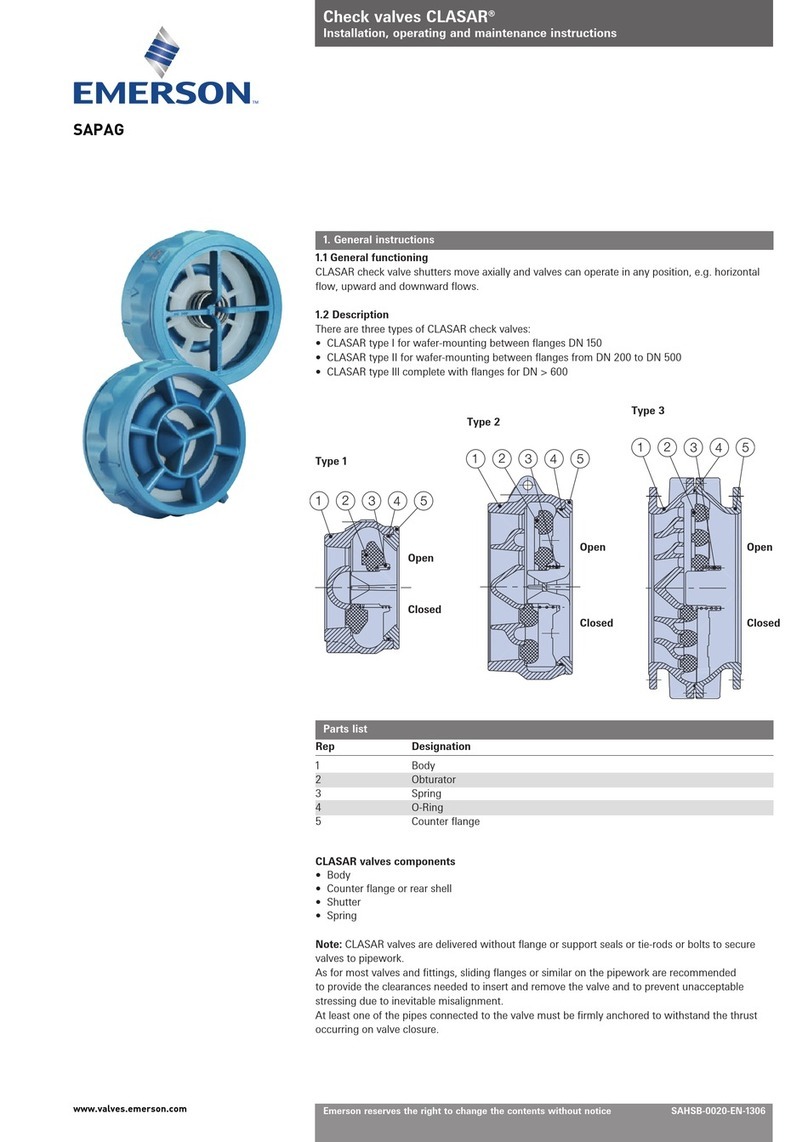
Emerson ENARDO 860 Series User manual
Other Emerson Control Unit manuals
Emerson
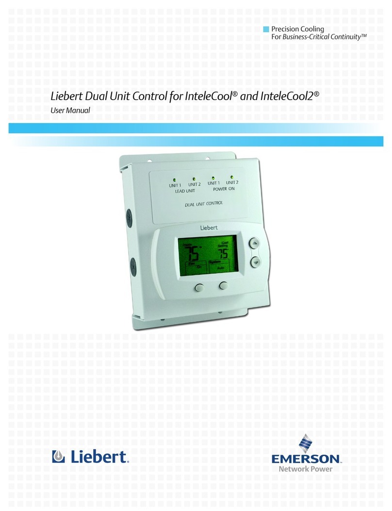
Emerson Clarkson series User manual

Emerson
Emerson Raimondi HPA 150 Installation and operating instructions
Emerson
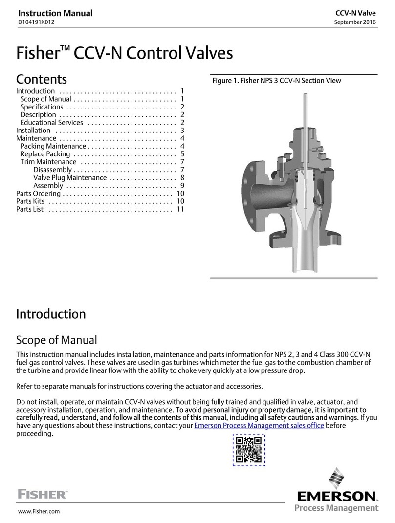
Emerson Fisher CCV-N User manual

Emerson
Emerson Bettis 2000 Series User manual

Emerson
Emerson AVENTICS TV04-CV User manual
Emerson
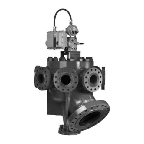
Emerson Fisher Multiport Flow Selector User manual
Emerson
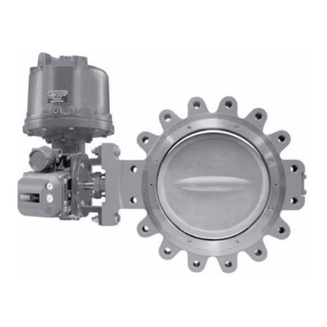
Emerson Fisher Control-Disk NPS 14 CL150 User manual

Emerson
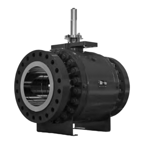
Emerson Fisher 63EG-98HM User manual
Emerson
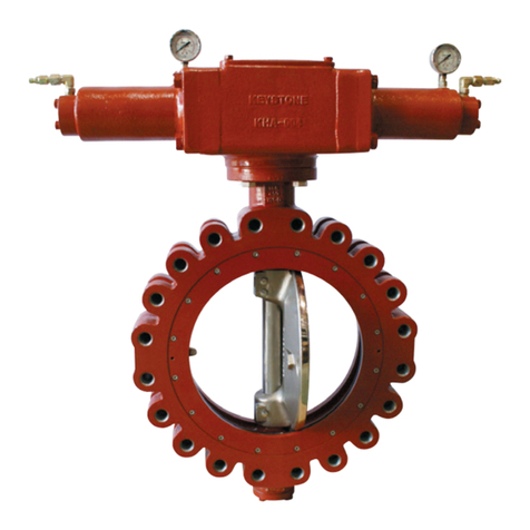
Emerson Fisher DSV1000 User manual
Emerson
Emerson KEYSTONE V30 Series User manual
Emerson
Emerson Fisher ME00124272 Configuration guide
Emerson
Emerson FISHER LR128 Series User manual
Emerson
Emerson Fisher SS-83 User manual
Emerson
Emerson 740 Series Installation instructions
Emerson
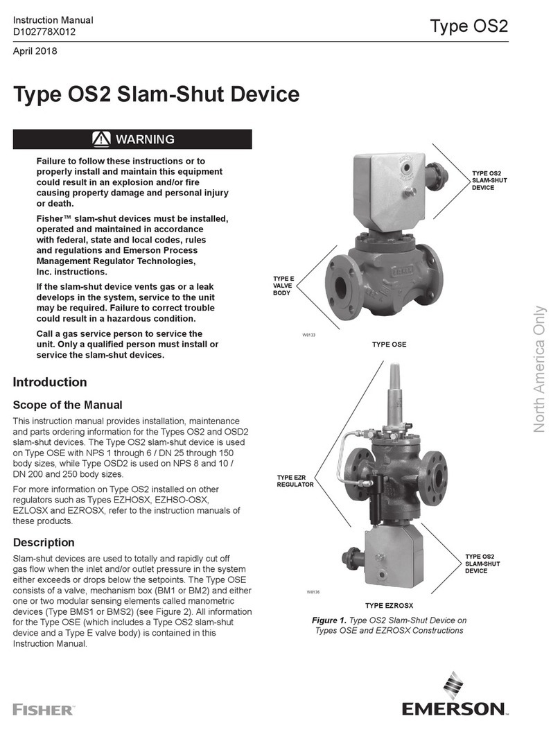
Emerson Fisher OS2 User manual

Emerson
Emerson ANDERSON GREENWOOD PILOT 9300 Series User manual
Emerson
Emerson Fisher ED User manual
Emerson
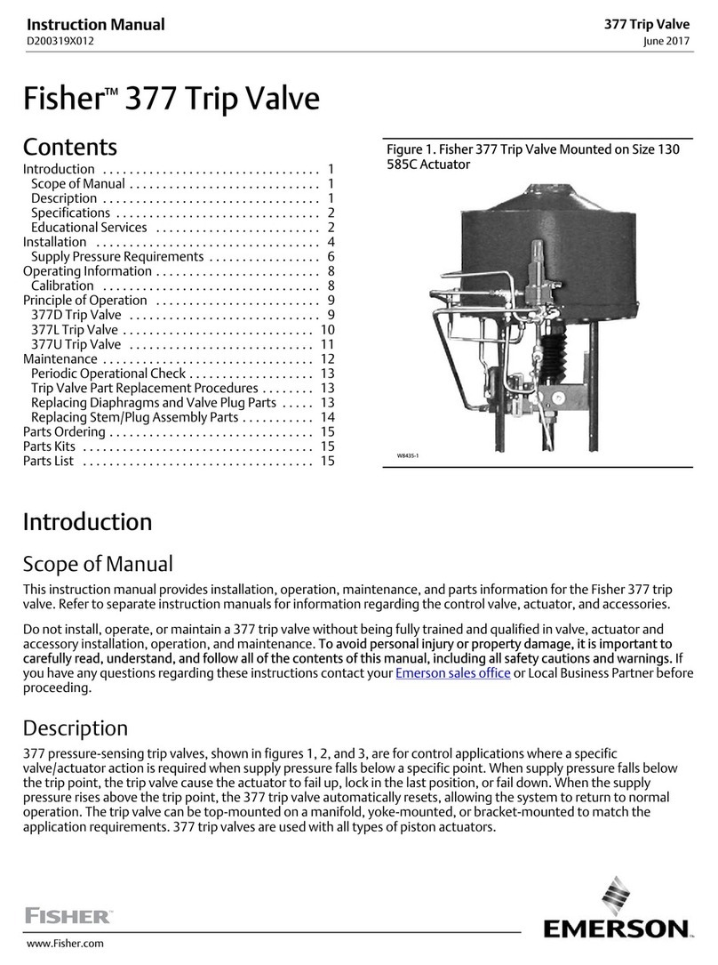
Emerson Fisher 377 User manual
Emerson
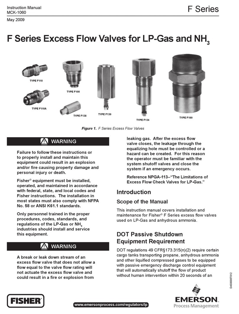
Emerson Fisher F Series User manual
Emerson
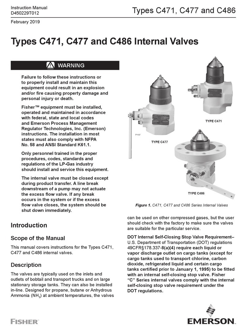
Emerson C471 User manual
Popular Control Unit manuals by other brands

Festo
Festo Compact Performance CP-FB6-E Brief description

Elo TouchSystems
Elo TouchSystems DMS-SA19P-EXTME Quick installation guide

JS Automation
JS Automation MPC3034A user manual

JAUDT
JAUDT SW GII 6406 Series Translation of the original operating instructions

Spektrum
Spektrum Air Module System manual

BOC Edwards
BOC Edwards Q Series instruction manual

KHADAS
KHADAS BT Magic quick start

Etherma
Etherma eNEXHO-IL Assembly and operating instructions

PMFoundations
PMFoundations Attenuverter Assembly guide

GEA
GEA VARIVENT Operating instruction

Walther Systemtechnik
Walther Systemtechnik VMS-05 Assembly instructions

Altronix
Altronix LINQ8PD Installation and programming manual


