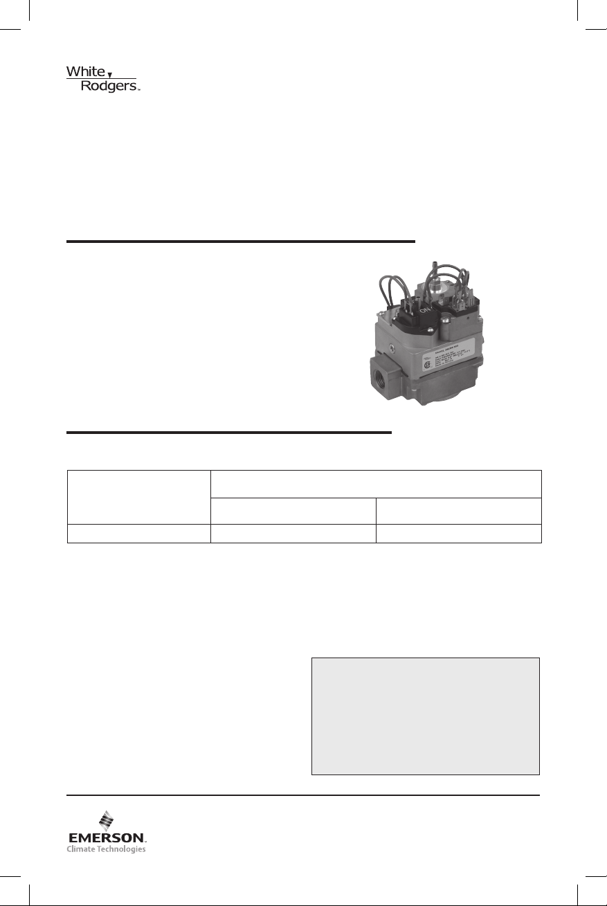
Emerson White Rodgers 36C94-303 User manual
Other Emerson Control Unit manuals

Emerson
Emerson Fisher Vee-Ball V150 User manual

Emerson
Emerson ANDERSON GREENWOOD 4142HF Manual

Emerson
Emerson Fisher 63EGLP Series User manual

Emerson
Emerson SAPAG 8400 Series Technical specifications

Emerson
Emerson Bettis XTE3000 User manual

Emerson
Emerson EX4 User manual

Emerson
Emerson ANDERSON GREENWOOD 9300H User manual

Emerson
Emerson Fisher ET User manual

Emerson
Emerson KEYSTONE F580 Setup guide

Emerson
Emerson KTM Hindle 300 Series User manual

Emerson
Emerson VAREC Series Operation and maintenance manual

Emerson
Emerson fisher EDR User manual

Emerson
Emerson Anderson Greenwood 93 Series User manual

Emerson
Emerson Crosby HSJ Series Manual

Emerson
Emerson Fisher Large ET User manual

Emerson
Emerson Fisher DSV1000 User manual

Emerson
Emerson Keystone 952 User manual

Emerson
Emerson IC200UEM001 User manual

Emerson
Emerson Baumann 89000 User manual

Emerson
Emerson KTM Series Manual


Popular Control Unit manuals by other brands

Festo
Festo Compact Performance CP-FB6-E Brief description

Elo TouchSystems
Elo TouchSystems DMS-SA19P-EXTME Quick installation guide

JS Automation
JS Automation MPC3034A user manual

JAUDT
JAUDT SW GII 6406 Series Translation of the original operating instructions

Spektrum
Spektrum Air Module System manual

BOC Edwards
BOC Edwards Q Series instruction manual

KHADAS
KHADAS BT Magic quick start

Etherma
Etherma eNEXHO-IL Assembly and operating instructions

PMFoundations
PMFoundations Attenuverter Assembly guide

GEA
GEA VARIVENT Operating instruction

Walther Systemtechnik
Walther Systemtechnik VMS-05 Assembly instructions

Altronix
Altronix LINQ8PD Installation and programming manual