Emerson RXi User manual

Quick Start Guide
GFK-3072F
Mar 2021
RXi –Panel PC
QUICK START GUIDE

i RXi –Panel PC Quick Start Guide GFK-3072F
Caution Notes as Used in this Publication
WARNING
Warning notices are used in this publication to emphasize that hazardous voltages, currents, temperatures, or other
conditions that could cause personal injury exist in this equipment or may be associated with its use.
In situations where inattention could cause either personal injury or damage to equipment, a Warning notice is used.
CAUTION
Caution notices are used where equipment might be damaged if care is not taken.
NOTICE
Notice tags are used where special attention is required to successfully complete a task.
Note: Notes merely call attention to information that is especially significant to understanding and operating the equipment.
These instructions do not purport to cover all details or variations in equipment, nor to provide for every possible
contingency to be met during installation, operation, and maintenance. The information is supplied for informational
purposes only, and Emerson makes no warranty as to the accuracy of the information included herein. Changes,
modifications, and/or improvements to equipment and specifications are made periodically and these changes may or
may not be reflected herein. It is understood that Emerson may make changes, modifications, or improvements to the
equipment referenced herein or to the document itself at any time. This document is intended for trained personnel
familiar with the Emerson products referenced herein.
Emerson may have patents or pending patent applications covering subject matter in this document. The furnishing of
this document does not provide any license whatsoever to any of these patents.
Emerson provides the following document and the information included therein as-is and without warranty of any kind,
expressed or implied, including but not limited to any implied statutory warranty of merchantability or fitness for
particular purpose.

ii RXi –Panel PC Quick Start Guide GFK-3072F
Contents
Regulatory Information..............................................................1
Intended Use ................................................................................................................ 1
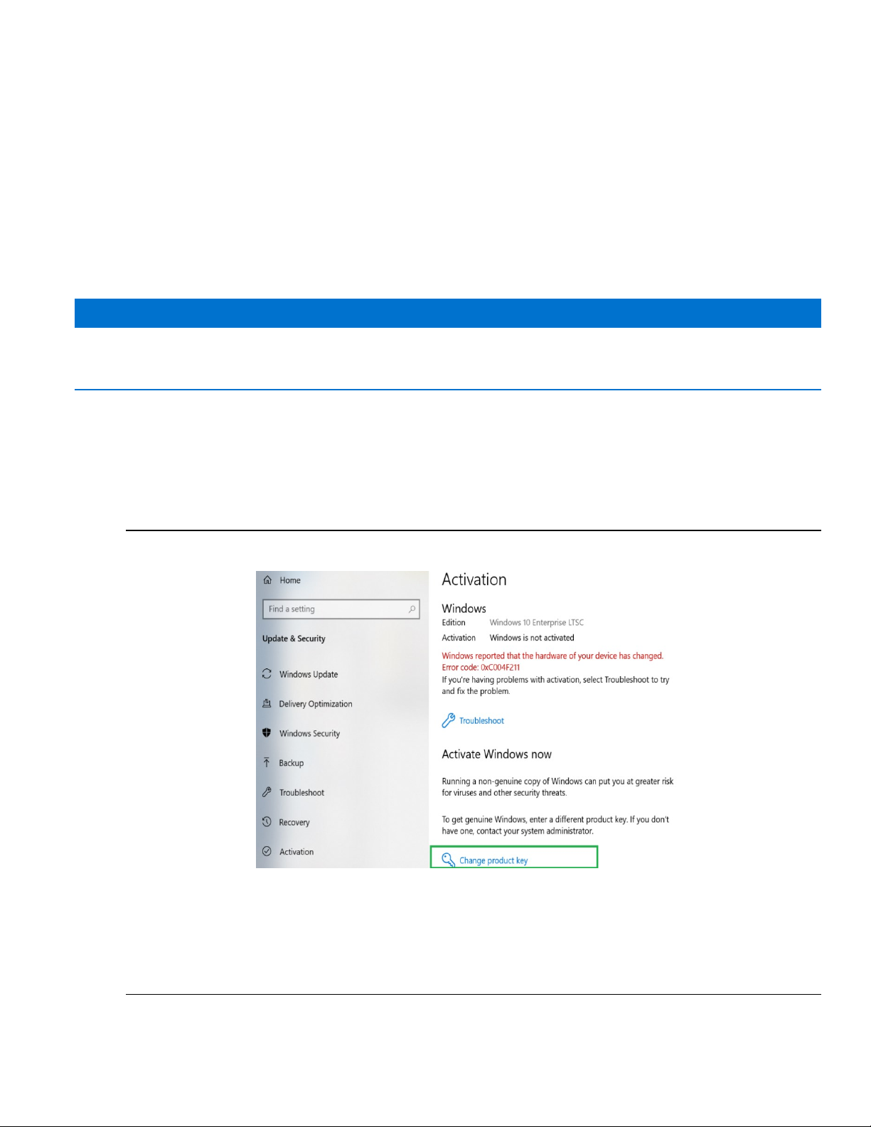
RXi Panel PC Windows Activation Procedure ..............................2
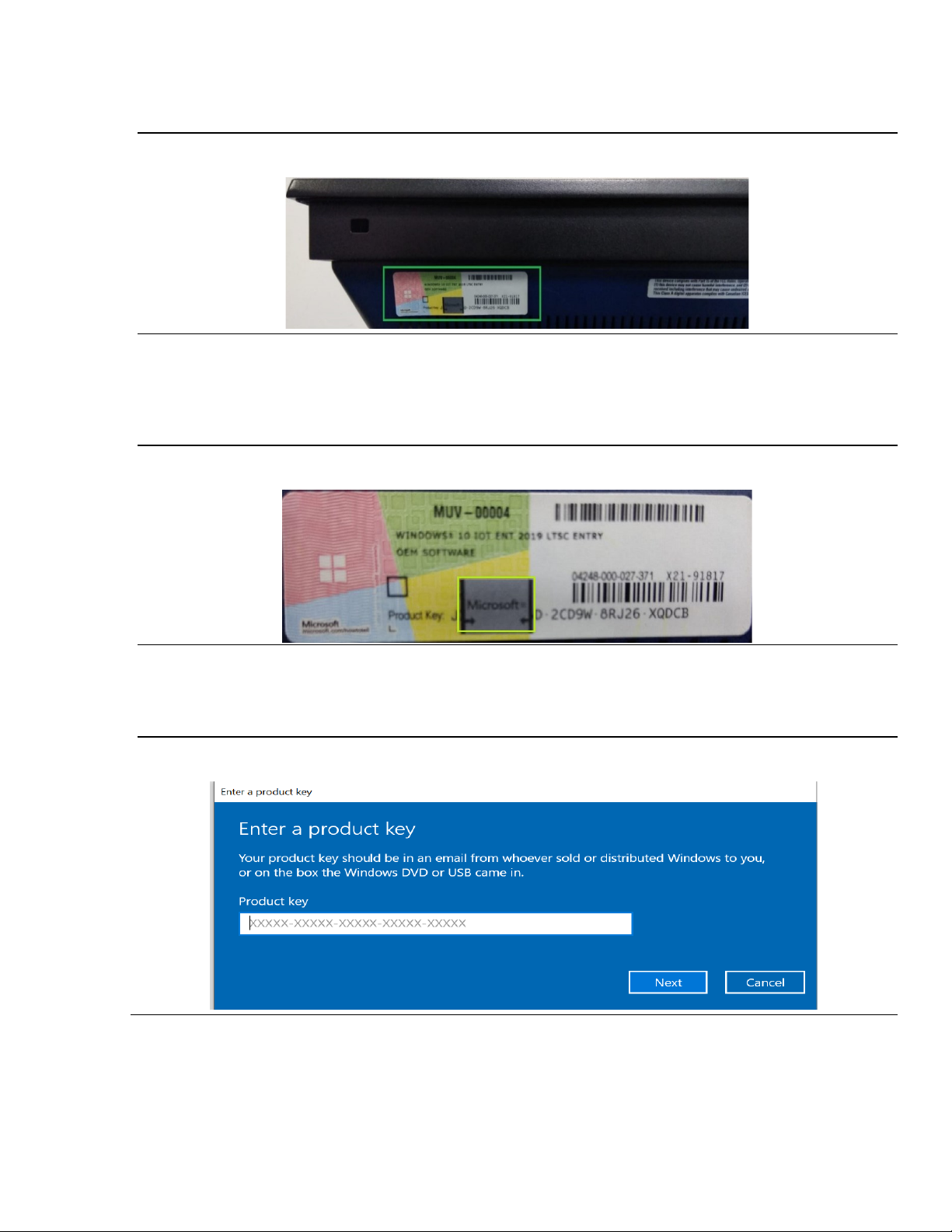
Activate a Windows 10 IoT Enterprise LTSC device Using an Internet Connection.... 2
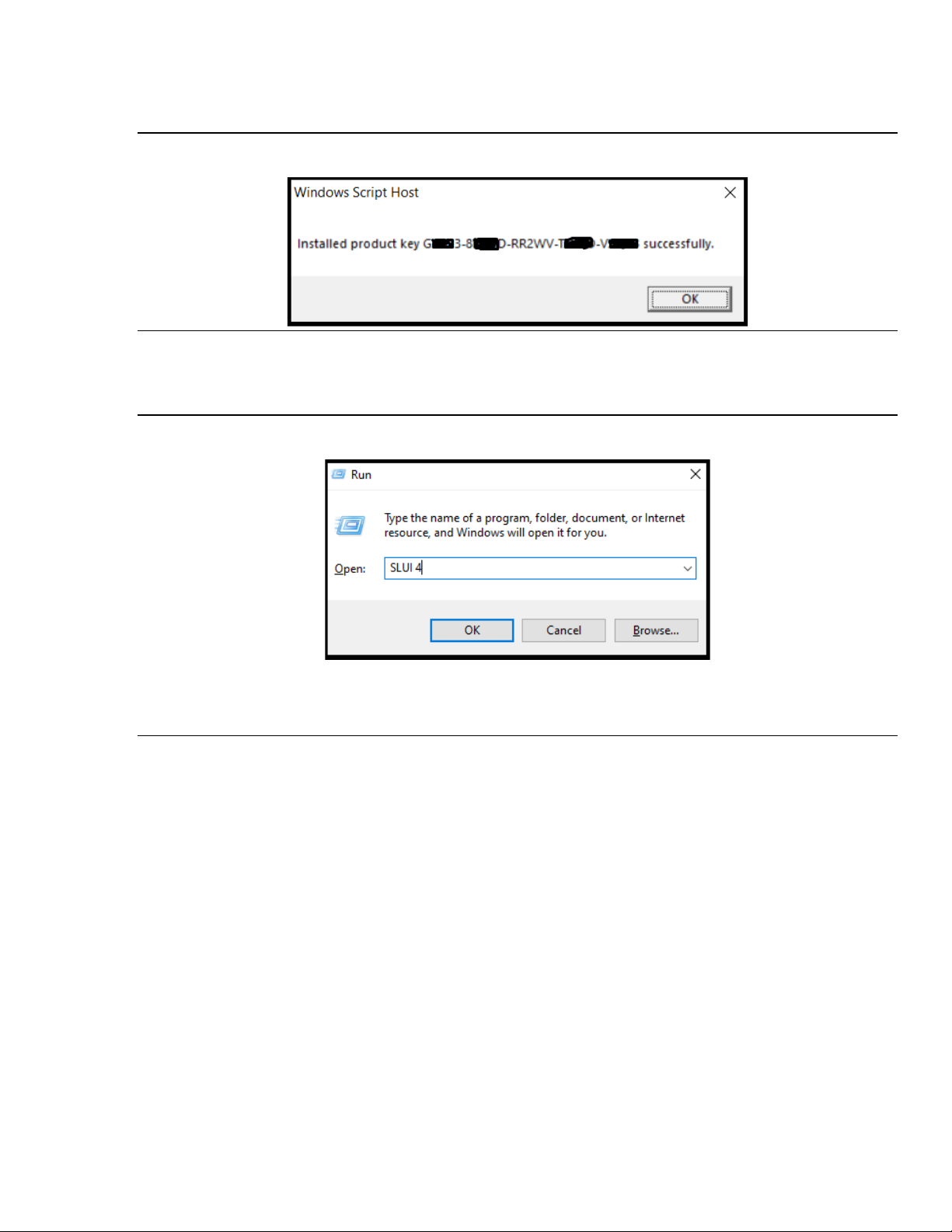
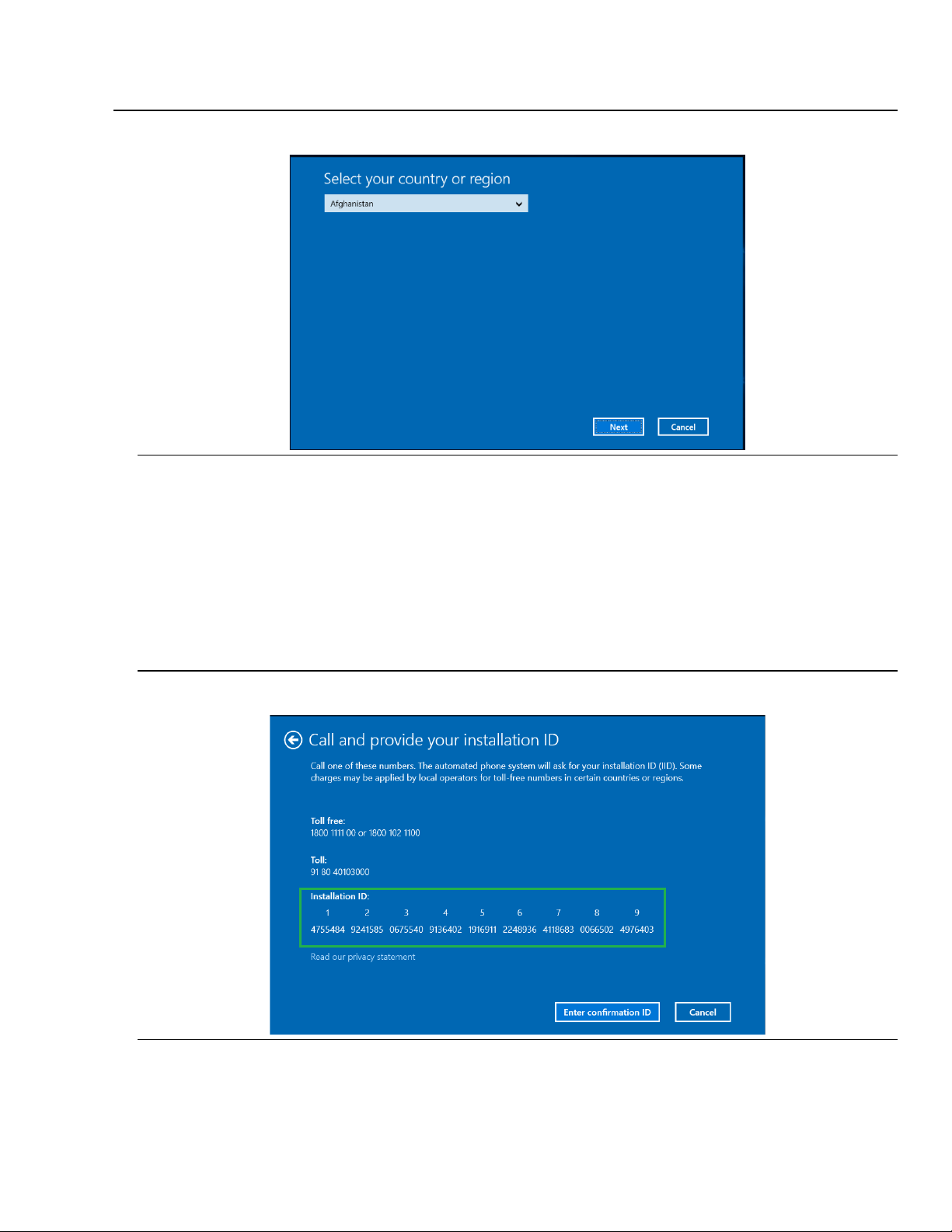
Activate a Windows 10 IoT Enterprise LTSC Device Using a Telephone.................... 4
I/O and Connectors.....................................................................8
Base Model IO (IC758xxxxxxPC)................................................................................. 8
Ryzen Model IO (IC758xxxxxxPCX) ............................................................................ 8
Connecting Input Power (24V DC-in) ........................................................................... 8
Graphics Interface ........................................................................................................ 9
DP++ Port........................................................................................................... 9
BIOS Setting....................................................................................................... 9
RJ45 LAN Ports ............................................................................................................ 9
Features ............................................................................................................. 9
BIOS Setting....................................................................................................... 9
USB Ports ..................................................................................................................... 9
BIOS Setting....................................................................................................... 9
Wake-On-USB Keyboard/Mouse ....................................................................... 9
Serial Ports (UART).................................................................................................... 10
Audio .......................................................................................................................... 10
Rear Audio ....................................................................................................... 10
BIOS Setting..................................................................................................... 10
I/O Connectors ........................................................................................................... 10
Serial ATA (SATA) Connector.......................................................................... 10
Features .................................................................................................. 10
BIOS Setting .................................................................................................. 10
Expansion Slots.......................................................................................................... 11
Micro SD Socket............................................................................................... 11
LVDS LCD Panel Connector ...................................................................................... 11
BIOS Setting..................................................................................................... 11
AIO/DIO Connector .......................................................................................... 11
Battery (Base Models) ................................................................................................ 12
Battery (Ryzen Models) .............................................................................................. 13
LED Indicators ............................................................................................................ 14
Operation Status LEDs (Screen)...................................................................... 14
Ethernet Port Operation LEDs ......................................................................... 14
Mounting Information..............................................................15
Panel Mount ............................................................................................................... 15
Panel Cutout Dimensions................................................................................. 15
Installation Steps .............................................................................................. 16
Mounting to Modular Display ...................................................................................... 17
VESA Mount ............................................................................................................... 20
VESA Mount Dimensions ................................................................................. 20

1 RXi –Panel PC Quick Start Guide GFK-3072F
Regulatory Information
The FCC requires the following note to be published according to the FCC guidelines:
NOTE: This device complies with part 15 of the FCC Rules. Operation is subject to the following two conditions: (1) This device may not cause
harmful interference, and (2) this device must accept any interference received, including interference that may cause undesired operation.
CAUTION
Changes or modifications not expressly approved by the party responsible for compliance could void the user's authority
to operate the equipment.
Industry Canada requires the following to be published: CAN ICES-3 (A)/NMB-3 (A)
Intended Use
The RXi Panel PC is intended for use in industrial environments only. Adherence to supplied documentation is part of the
intended use. Installation, commissioning, and maintenance shall be carried out by qualified personnel. For more
information, please consult GFK-3163, RXi2 LP/ RXI Display Installation and Maintenance Requirements.

2 RXi –Panel PC Quick Start Guide GFK-3072F
RXi Panel PC Windows Activation Procedure
The preloaded Windows 10 IOT Enterprise image on Panel PC is not activated by default. The product key is present on the
rear of the Panel PC backing module to activate Windows 10 IOT Enterprise.
Note: The user should write down the product key before installing the RXi Panel PC. The product key may not be
accessible after installation.
Activate a Windows 10 IoT Enterprise LTSC device Using an Internet
Connection
NOTICE
It is required to place the Panel PC unit in a DMZ network architecture with internet access temporarily to perform the
activation with Microsoft.
1. Press the Windows key (Start button), then go to Settings > Update and Security > Activation (or)
Launch This PC properties.
2. Proceed with license activation by pressing the Change Product Key option which is highlighted in the
below image in green color.
Figure 1: Activation
Note: Ignore the error message –“Windows reported that the hardware of your device has changed. Error code:
0xC004F211.”

3 RXi –Panel PC Quick Start Guide GFK-3072F
3. Find the Product Key Sticker that is present on the rear side of the Panel PC backing module as shown in
(Figure 2).
Figure 2: Product Key Sticker
4. Part of the Product Key may be covered with gray scratch ink. Remove (scratch) the ink layer to reveal
the Product Key as shown in (Figure 3).
Figure 3: Removing the Scratch Layer
5. Enter the retrieved Product Key into the popup box and press Next (Figure 4).
Figure 4: Enter the Product Key
6. The Windows 10 product key is now active.

4 RXi –Panel PC Quick Start Guide GFK-3072F
Activate a Windows 10 IoT Enterprise LTSC Device Using a Telephone
1. On the device, open a command prompt as the administrator.
2. Navigate to the <system drive>:\Windows\System32 with folder type slmgr.vbs /ipk XXXXX-XXXXX-
XXXXX-XXXXX-XXXXX. The XXXXX characters will be the 25-character product key present on the side
of the device (Figure 5).
3. Product Key is present on the Panel PC backing module as showing below.
Figure 5: Product Key Sticker
4. The part of the Product Key is covered by the scratch layer as highlighted below. The user needs to
retrieve this by removing the scratch layer (scratch-off Microsoft labeled layer) as highlighted below.
Figure 6: Revealing the Product Key

5 RXi –Panel PC Quick Start Guide GFK-3072F
5. After step 2, a message display stating that the Product Key was installed successfully. Click OK to
proceed.
Figure 7: Windows Script Host
6. Press the Win+R keys to open Run, then type: SLUI 4 and click on OK.
Figure 8: Run the SLUI 4 Command
Note: There is a space between SLUI and 4. The 4 option instructs SLUI to launch the telephone
activation UI.

6 RXi –Panel PC Quick Start Guide GFK-3072F
7. Select your country or region and click Next. It navigates to next page where we can see Installation ID.
Figure 9: Select Country or Region
8. Call the Microsoft Product Activation Center. (The phone number is provided based on the selected
region.) Proceed through the automated menu and answer a few questions about the Windows
activation.
9. At the end of the automated menu, the user will need to confirm the 63-digit Installation ID number.
Enter the Installation ID number as shown in Figure 10. The Installation ID number will be grouped into
sets of nine (seven digits per set).
Figure 10: Technical Support

7 RXi –Panel PC Quick Start Guide GFK-3072F
10. The phone activation system will provide the user with a 48-digit Confirmation ID. Enter the
Confirmation ID as seen in (Figure 11).
Figure 11: Confirmation ID
11. Once the Confirmation ID has been entered, click the Activate Windows button.
12. To verify the licensing status, open the command prompt as the Administrator on the device.
13. Navigate to the <system drive >:\Windows\System32 folder, type
cscript slmgr.vbs /dlv, and verify that the License Status now displays Licensed.
Example: c:\Windows\System32>cscript slmgr.vbs /dlv
Figure 12: Command Prompt

8 RXi –Panel PC Quick Start Guide GFK-3072F
I/O and Connectors
The rear panel I/O port arrangement consists of the following:
Base Model IO (IC758xxxxxxPC).
Figure 13: Rear Panel Arrangement
Ryzen Model IO (IC758xxxxxxPCX)
Figure 14: Rear Panel Arrangement
Connecting Input Power (24V DC-in)
To connect to power, follow these steps:
1. Verify that the power cable is not energized.
2. Loosen the screw clamps on the mating power connector.
3. Strip the insulation from the power cables.
4. Secure the power cable to the mating connector, noting polarity, and tighten
the screw clamps. The torque for the attaching screws is 0.3 Nm (2.26 in-lb).
5. Apply dc power to the unit. During normal startup and operation, the LED
status indicator displays as follows:
•Solid amber while the RXi - Industrial Display unit is starting up
•Solid green during normal operation
6. Once power is applied, the unit begins initializing. The first thing to display is the splash screen.
Be sure to connect a DC power cord to this 3-pin power connector. Using a voltage out of the range may fail to
boot the system or cause damage to the system board.

9 RXi –Panel PC Quick Start Guide GFK-3072F
Graphics Interface
The display port consists of the following:
DP++ Port
The DP++ is a digital display interface used to connect a display device such as a computer monitor. It is used to transmit
audio and video simultaneously. The interface, which is developed by VESA, delivers higher performance features than any
other digital interface.
BIOS Setting
Configure the display device in the Chipset menu (“DISPLAY control” submenu) of the BIOS.
RJ45 LAN Ports
Features
2 Intel® I210IT PCI Express Gigabit Ethernet controllers
The LAN ports allow the system board to connect to a local area network through a network hub or router.
BIOS Setting
Configure the onboard LAN in the Advanced menu (“Wakeup Configuration” submenu) of the BIOS. Refer to chapter 3 for
more information.
USB Ports
The USB ports allow for data exchange between your computer and a wide range of simultaneously accessible external Plug
and Play peripherals.
The RXi –Panel PC is equipped with 2 onboard USB 3.0 ports (USB 0-1) in the small configuration with an additional 2 USB
2.0 ports (USB 4-5) in the large box configuration.
BIOS Setting
Configure the onboard USB in the Advanced menu (“Wakeup Configuration” submenu) of the BIOS. Refer to chapter 3 for
more information.
Wake-On-USB Keyboard/Mouse
The Wake-On-USB Keyboard/Mouse function allows you to use a USB keyboard or USB mouse to wake up a system from the
S3 (STR - Suspend To RAM) state.

10 RXi –Panel PC Quick Start Guide GFK-3072F
Serial Ports (UART)
Serial
Connection
Pin
Function
RS232
1
TXD
2
RXD
3
RTS
4
CTS
5
GND
RS485
6
TX+
7
TX-
8
RX+
9
RX-
10
GND
Audio
Rear Audio
The system board is equipped with 2 audio jacks (Line-out and Mic-in). A jack is a one-hole connecting interface for inserting
a plug.
•Line-out Jack (Lime)
This jack is used to connect a headphone or external speakers.
•Mic-in Jack (Pink)
This jack is used to connect an external microphone.
BIOS Setting
Configure the onboard Audio device in the Chipset menu (“SB HD Azalia Configuration” submenu) of the BIOS.
I/O Connectors
Serial ATA (SATA) Connector
Features
•1 Serial ATA 3.0 port with data transfer rate up to 6Gb/s
•Integrated Advanced Host Controller Interface (AHCI) controller
The Serial ATA connector is used to connect the Serial ATA device. Connect one end of the Serial ATA data connector to a
SATA connector on the other end to your Serial ATA device.
BIOS Setting
Configure the Serial ATA drive in the Chipset menu (“SB SATA Configuration” submenu) of the BIOS. Refer to chapter 3 for
more information.

11 RXi –Panel PC Quick Start Guide GFK-3072F
Expansion Slots
Micro SD Socket
The micro SD socket allows you to install a micro SD card for the expansion of available storage.
LVDS LCD Panel Connector
The system board allows you to connect an LCD Display Panel with the LVDS LCD panel connector. This
connector transmits video signals and power from the system board to the LCD Display Panel.
Refer to the right side for the pin functions of the LVDS connector.
BIOS Setting
Configure the LCD panel in the Chipset menu (“DISPLAY control” submenu) of the BIOS. Refer to
Chapter 3 for more information.
AIO/DIO Connector
AIO/DIO connector provides functionality to external devices that are connected to the connector.
(FOR FUTURE USE)

12 RXi –Panel PC Quick Start Guide GFK-3072F
Battery (Base Models)
Base models are designated with a PC in their part number (IC758xxxxxxPC).
The lithium-ion battery powers the real-time clock and CMOS memory. It is an auxiliary source of power when the main
power is shut off or disconnected. It is a standard CR2032 battery and is accessible on the bottom of the computing
module when separated from the screen (as shown in Figure 15)
Safety Measures
•Danger of explosion if battery incorrectly replaced.
•Replace only with the same or equivalent type recommended by the manufacturer.
•Dispose of used batteries according to local ordinances.
Figure 15: CR2032 Battery
7 to 10 Inch
12 to 24 Inch
WARNING
Use of Another Battery May Present a Risk of Fire or Explosion.
Replace Battery with Panasonic Model CR2032 only.
CAUTION
Battery May Explode if Mistreated. Do not Recharge, Disassemble, or Dispose of In Fire.

13 RXi –Panel PC Quick Start Guide GFK-3072F
Battery (Ryzen Models)
Ryzen models are designated with a PCX in their part number (IC758xxxxxxPCX).
The lithium-ion battery powers the real-time clock and CMOS memory. It is an auxiliary source of power when the main
power is shut off or disconnected. It is a standard CR2032 battery and is accessible on the bottom of the computing
module when separated from the screen (as shown in Figure 15)
Safety Measures
•Danger of explosion if battery incorrectly replaced.
•Replace only with the same or equivalent type recommended by the manufacturer.
•Dispose of used batteries according to local ordinances.
Figure 16: CR2032 Battery for Ryzen Models
WARNING
Use of Another Battery May Present a Risk Of Fire or Explosion.
Replace Battery With Tohoku Murata Manufacturing Co. LTD. Model CR2032 or CR2032W Only.
CAUTION
Battery May Explode if Mistreated. Do not Recharge, Disassemble, or Dispose of In Fire.

14 RXi –Panel PC Quick Start Guide GFK-3072F
LED Indicators
Operation Status LEDs (Screen)
All RXi Industrial Displays have a tri-color LED built into the screen that provides visual indication of the operation status.
LED State
System State
Amber, Solid
Operating system starting
Green, Solid
Normal operating state
Green, Blinking
Backlight off
Red, Blinking
Backlight failure
Off
Power not applied to the unit
Ethernet Port Operation LEDs
LED
LED State
Operating State
Speed
Yellow, ON
10/100/1000
Link Activity
Green, ON
Link Status

15 RXi –Panel PC Quick Start Guide GFK-3072F
Mounting Information
Panel Mount
The RXi Panel PC can be panel-mounted as presented in the section entitled Mounting to Modular Display.
A Type 4, Type 4X, or IP 66 rating is achieved when mounted to the flat surface of a sufficiently rated enclosure. Please follow
the instructions in the section entitled Installation Steps.
Panel Thickness: 16
1
to 7 gauge (1.6 to 5 mm)
Panel Thickness: 1.6 to 5mm
All measurements within ±0.5mm
Panel Cutout Dimensions
Figure 17: Panel Cutout Dimensions
Width
Height
Display Size (in)
Width (mm)
Height (mm)
7
183.5
128.5
10
255.5
174
12
317
214.5
15
398
245.5
19
482
297
24
581
360
All panel cutout measurements should be within ±0.5 mm.
Values presented are width and height only.
1
For IP66 installations of 12-inch displays (IC758CSW12SCREEN-A and IC758COW12SCREENSLR-A) use a 14 to 7 gauge (2 to 5 mm) thick panel.

16 RXi –Panel PC Quick Start Guide GFK-3072F
Installation Steps
1. Verify that the gasket is present and properly seated in the bezel channel located on the sides of the unit.
2. Carefully insert the Panel PC into the mounting panel cutout.
Figure 18: Panel Install View
3. Insert the hook of the mounting bracket into the mounting hole as displayed in the following figure.
Figure 19: Mounting Bracket Insertion
4. Tighten all mounting brackets by hand until the gasket seal contacts the mounting surface uniformly.
5. In a cross pattern around the monitor tighten all mounting clip screws to a torque of 13 to 13.9 in-lbs. (15
to 16kgf-cm) making sure not to overtighten the bracket.
Figure 20: Tighten Mounting Bracket

17 RXi –Panel PC Quick Start Guide GFK-3072F
Mounting to Modular Display
Figure 21: 7" Mount
Figure 22: 10" mount
Other manuals for RXi
8
Table of contents
Other Emerson Touch Panel manuals

Emerson
Emerson GFK-3072D User manual

Emerson
Emerson Rosemount 751 User manual

Emerson
Emerson RXi User manual

Emerson
Emerson Rosemount 752 FOUNDATION User manual

Emerson
Emerson RXi User manual

Emerson
Emerson RXi User manual

Emerson
Emerson Rosemount 752 User manual

Emerson
Emerson RXi Web Panel User manual

Emerson
Emerson Site Supervisor 10.1 User manual

Emerson
Emerson RXi User manual