EMS EMS520 User manual

EMS520 MANUAL VOLUME 4
Rev 1.3 RCU, Modbus

1
CONTENTS
LIMITED WARRANTY............................................................................................................................................................2
CUSTOMER SERVICE ............................................................................................................................................................3
SECTION 1 SYSTEM DESCRIPTION ........................................................................................................................................4
SYSTEM SPECIFICATIONS................................................................................................................................................................6
SECTION 2 INSTALLATION CONSIDERATIONS.......................................................................................................................9
BEFORE START UP.........................................................................................................................................................................9
SECTION 3 CONTROL UNIT PAGE DESCRIPTION .................................................................................................................11
CONTROL UNIT SCREENS ..............................................................................................................................................................11
SECTION 4 MODBUS ..........................................................................................................................................................28
MODBUS ADDRESS INFORMATION .................................................................................................................................................28
RS/485-MODBUS COMMUNICATIONS AND CONNECTION TO CUSTOMER DATA AQUSITION SYSTEMS........................................................29
SECTION 5 OPTIONAL SNAP-IN ..........................................................................................................................................29
OPTIONAL SNAP-IN ALARM RELAY/IO WIRING.................................................................................................................................29
OPTIONAL SNAP-IN ANALOG OUTPUT CONNECTIONS........................................................................................................................29
SECTION 10 ALARM MATRIX..............................................................................................................................................30

2
LIMITED WARRANTY
EMS warranty is found in the CD supplied with monitor shipment. If you cannot find it or you
document.
WARNINGS AND SAFETY GUIDELINES
GUIDELINES FOR USER SAFETY AND EQUIPMENT PROTECTION
This manual is intended to aid trained and competent personnel in the installation of this equipment. Only a technician or
engineer trained in the local and national electrical standards should perform tasks associated with the electrical wiring of
this device.
WARNINGS
▪Under no circumstances will Environmental Monitor Service, Inc. be liable or responsible for any consequential
damage that may arise because of installation or use of this equipment.
▪All examples and diagrams shown in the manual are intended to aid understanding. They do not guarantee
operation.
▪Environmental Monitor Service, Inc. accepts no responsibility for actual use of this product based on these examples.
▪Due to the great variety of possible applications for this equipment, the user must assess the suitability of this
product for specific applications.
▪Make sure to have safety procedures in place to stop any connected equipment in a safe manner if the controller
should malfunction or become damaged for any reason.
▪Do not replace electrical parts or try to repair this product in any way.
▪Only qualified factory trained service personnel trained in is operation should open the device’s housing or carry out
repairs.
▪The manufacturer is not responsible for problems resulting from improper or irresponsible use of this device.
▪You may cause an electric shock, fire or damage the equipment if you ignore any of these safety precautions.

3
CUSTOMER SERVICE
Before you ship equipment to our factory please call or email our Service Response Center at 1-800-864-2814 ext 14. When you call
in, our Customer Service Representative will determine a course of action.
E-mail: techsupport@emsct.com
CLAIMS FOR DAMAGED SHIPMENTS
Inspect all instruments thoroughly on receipt. Check material in the container (s) against the enclosed packing list. If the contents
are damaged and/or the instrument fails to operate properly, notify the carrier and Environmental Monitor Service immediately.
The following documents are necessary to support claims:
Original freight bill and bill of lading
Original invoice or photocopy of original invoice
Copy of packing list
Photographs of damaged equipment and container
You may want to keep a copy of these documents for your records also.
Refer to the instrument name/EMS number, serial number, sales order number, and your purchase order number on all claims.
Upon receipt of a claim, we will advise you of the disposition of your equipment for repair or replacement.
SHIPPING DISCREPANCIES
Check all containers against the packing list immediately on receipt. If a shortage or other discrepancy is found, notify the carrier and
Environmental Monitor Service immediately. WE will not be responsible for shortages against the packing list unless they are reported
promptly.
EMS will not be responsible for shortages against the packing list unless they are reported within 3 days of receiving of your
shipment.

4
SECTION 1 SYSTEM DESCRIPTION
TRANSMISSOMETER /RETRO REFLECTOR
The EMS520 is a precision, double-pass, dual beam Transmissometer that consists of a transceiver (transmitter/receiver) mounted on
one side of a stack or duct and a passive reflector mounted on the opposite side. The LED source, photo detectors, and all
measurement/reference optics used in opacity measurement are housed in the transceiver.
Normal mode of operation
The Dual beam measurement system has a stack mounted Transmissometer sensor system consists of an optical transceiver mounted
on one side of the stack and a retro reflector mounted on the other. To avoid errors due to ambient light, the narrow beam LED (See
Drawing) is electronically modulated and projects a collimated beam of light, which is split into a reference beam, and a measurement
beam by an optical Beam splitter. The reference beam is directed to the reference detector, RD. The measurement beam is projected
across the stack to a Retro reflector that returns the beam back across the stack to a beam splitter and directs the measurement beam
to the measurement detector, MD. A portion of
the returning light is also sent to the TTL (Thru the
Lens) bulls-eye target viewed through a window
provided at the rear of the Transmissometer. The
bulls-eye is used to correct changes in alignment
and is unique in that no moving parts are used!
The ratio of the measurement and reference
detectors is used to provide Transmittance 2 (T 2)
signal. Because the same light source is used for
both detectors, and a Measurement / Reference
ratio is used throughout for the calculations, the
monitor is insensitive to variations in light
intensity. Since all measurements are made on a
ratio basis, all resulting computations are
independent of the absolute intensity of the LED
source or contamination of the optics associated with the collection and focusing of the energy from the LED. The (T 2) signal is
converted to a current format and sent to the control unit for processing. At the control unit the signal is processed to read 0-100%
Opacity, provide alarms and outputs.
Internal calibration system, zero mode
Zero and span calibration checks can be initiated manually, automatically or by a PLC or computer. During the zero calibration mode
a calibrated zero reflector is placed in front of the transceiver optical package testing all optical surfaces and electronic components
to assure zero point has not changed.
Internal calibration system, Span mode
In the span mode, a Span filter of known Neutral Density is placed in the measurement path and produces a specific upscale reading
in accordance with the latest E.P.A. requirements. The zero and span cycle provides a continuous check of all the optical components
and surfaces, the main lamp, the detector, interconnecting wiring, control unit and computation analysis.
5
RCU
The RCU provides instrument control functions, opacity readings, alarms, analog outputs, communications, system information and
more. The color 5x7” viewing screen can be seen in low light levels and bright. The RCU is rated NEMA 4X/IP65 when panel
mounted. Battery backup for all memory is typically 7 years.
The control unit should be mounted in a control room environment i.e., clean, temperature with max/min of +0oto +50 o C (+32 o to +
122 o F). The EMS520 control unit provides instrument control functions, opacity readings, alarm and fault indicators, analog outputs,
and diagnostics with contact closures.
Optional Air Purge Weather Cover System
The transceiver and reflector may be mounted in weather covers. The weather covers are fairly compact to allow movement around
them even on a three-foot walkway or platform. They protect the stack-mounted components from dirt, moisture; stack temperatures
within the specified ambient temperatures limits, and errant air currents around the stack.
The air purge system constantly circulates air past the optical window. The air flow is directed through the hose to an air plenum on
the stack side of the optical window. The air flow in the air plenum area results in reduced pressure and increased velocity. This
venturi effect tends to continually draw the air around the optical window into the purge air stream, thereby keeping the lens clean
for extended periods.
Alignment system
The EMS520 includes a built-in through-the-lens alignment system. The alignment target can be viewed through a window on the
transceiver. Adjustments to changes in alignment are provided by a 3-point alignment system, which is integral to the air plenum.
Cabling to Smart Service Module
Port 2, 6-pin R J25 connector Pin 1 (+), Pin 6 (-). RS-485 cabling may be up to 2000 feet in length. Belden P/N 3106A cable is
recommended. Note: Cable drawing and pin out at the end of drawing section.
OPTIONAL SNAP-IN: The standard cabling used between the RCU and other devises, s at a minimum 6-pair, #20 AWG, twisted,
shielded. Separation distance approximately 1000FT, more pairs or larger gage than 20 AWG is also acceptable.

6
SYSTEM SPECIFICATIONS
EMS520 Opacity/Dust Control unit:
Environmental Monitor Service, Inc.
Enclosure
IP65/NEMA4X (when panel mounted),
197x146.6x68.5mm (7.75" x 5.77" x2.7").
Graphic Display
5.7” Viewing area, 256 color, Icon driven
Approvals
CE, UL, cUL
Measurement Ranges
-5 to 100% Opacity, 0-2 Optical Density, 0-2000
mg.
Display Resolution
0.1 for Opacity and mg, 0.001 O.D.
Process Display screens
5 Numerical, 3 Trends.
Home Screen Navigation with virtual
touch keypad for data entry
Touch Icons for information and user interface
for Calibration, Fault, Alarms, Settings,
Displays, Service and About.
Battery back up
7 years typical at 25oC
S.D. Card
Back up by 2GB SD memory card. Optional
upgraded storage for data logs, alarm history,
data tables, backup ladder, HMI, and OS.
Alarm Reset
Automatic and manual.
Cal cycle initiate
Manual, Remote and Internal Clock.
OPLR (Exit Correlation Lx / 2*Lt)
0.3 to 1.0
Environment
Inside cabinet IP20 / NEMA1 (case), Panel
mounted IP65 / NEMA4X (front panel),
Operational temperature 0 to 50ºC (32 to
122ºF), Storage temperature -20 to 60ºC (-4 to
140ºF), Relative Humidity (RH) 5% to 95%
(non-condensing)
EMS provided 24Vdc Supply
Input: 90-240 VAC, 50/60 Hz, 0.55 amp +10%
Network
Protocol: MODBUS, type RS-485.

7
PS-1 Transceiver/ Reflector:
Enclosure
NEMA 4 watertight enclosure.
Path Length
Distance dependent.
Optical System
PS-1 Double Pass
Reflector
Distance dependent.
Light Source Aging Compensation
Automatic
Light Source Life
62,000 hours (> 7 years) Field replaceable
without removal
Ambient Temperature Limits
0 to +130oF (-17 to +54oC) (Cold weather option
available).
Process Gas
Up to 750oF (400 oC),
Alignment Verification
Built-in through-the-lens system standard
Mounting Flanges
3 inch IPS, 150# flange. Others available.
Ambient Light Immunity
Solid-state modulation (Meets ASTM D6216)

8
EMS520 Smart Service Module
Environmental Monitor Service, Inc.
Enclosure
Stainless Steel when in EMS WC, NEMA 4X
plastic when stand alone.
Graphic Display
1.5x2.25” Viewing area, LED Backlight
Approvals
CE, UL, cUL
Network
Protocol: MODBUS type RS-485.
RCU Display Resolution
0.1 for Opacity RCU, mg, 0.01 O.D. with DUST
RCU
Process Display screens
Local display for, Sensor data, Service
selections, Fault displays.
Battery back up
7 years typical at 25oC
Cal cycle initiate
Manual, Remote and Internal Clock.
Environment
Panel mounted IP65 / NEMA4X (front panel),
Operational temperature 0 to 50ºC (32 to
122ºF), Storage temperature -20 to 60ºC (-4 to
140ºF), Relative Humidity (RH) 5% to 95%
(non-condensing)
EMS provided 24Vdc Supply
Input: 90-240 VAC, 50/60 Hz, 0.55 amp +10%
Network
Protocol: MODBUS (ASCII or RTU mode),
type RS-485, optically isolated, RS-232.
2-wire to EMS Control Unit
RS485 Modbus to Control Unit
Design and performance:
Meet or exceeds 40 CFR 60 appendix B, PS-1
and ASTM D 6216
Spectral Response
Peak 500 to 600nm, less than 10% of peak
response outside 400 to 700 nm.
Angle of View/Angle of Projection
AV <4o, AP <4o.
Calibration Error/accuracy
+/- 1% of full scale
Response time
< 10 second
24 Hour Zero/ Calibration Drift
< 0.5% / < 0.5%
Operational Period
In excess of PS-1 required 336 Hrs.
Zero/Span Calibration
Manual or automatic with zero mirror and
neutral density filter
Process gas
Up to 750 oF (400o C) standard, higher available-
contact factory.

9
SECTION 2 INSTALLATION CONSIDERATIONS
BEFORE START UP
You must complete the following before start up is attempted.
•Check that all parts have the identical serial numbers.
•Measure and record flange -to-flange distance to verify it is the same as final check out sheet.
•If you are using a recorder, DAS, etc., DO NOT CONNECT THEM NOW. Outputs and inputs from
other sources should be left off until system has been completely checked according to the following instructions.
After system operation has been verified connect and test external connections.
•Read the instructions first to familiarize yourself with the instrument before attempting start up.
•The air purge and Weather cover system, Transceiver, Retro reflector, Service module must be installed and power
applied.
•Control unit must be installed and wired to the service module and customers equipment as applicable.
•All wiring and mechanical installations must be complete per drawings provided in this manual. All wiring must be
checked and power applied to both the control unit and the stack maintenance module.
•Beam Alignment procedure has been completed.
CONTROLUNIT GLOSSARY OF TERMS
OUTPUT TYPE SETUP –“Output type” refers to the 4-20mA outputs.
•Instant opacity, z/s outputted during calibration cycle.
•Average, opacity average z/s outputted during cal cycle.
•Last - instant opacity, last value is held during cal cycle.
•Note: Last should be used if you are using the output for process control signal.
ALARM AUTO/MANUAL SETUP –Press return/enter button to enter. Choose between 1-auto or 2- manual.
•Auto means when the high opacity alarm has been activated and when the level of smoke drops below the alarm point the
alarm contacts 02 & 04 and icon will reset automatically.
•Manual reset means when the high opacity alarm has been activated, pushing the return/enter button 04 contact will de-
energize but 02 will remain energized. When the level of smoke drops below the alarm point the return/enter button is
pushed and both 02 &04 will be de-energised.
OUTPUT SCALING SETUP –Press return/enter button to enter.

10
•Set Ch 1 or 2 to desired opacity range i.e, for 4ma to represent minimum opacity and 20mA to represent maximum
opacity. The 20mA value of 99.9 is used to represent 100%.
•Note; For CFR 40, PS-1 set the 4mA to -5% To get negative values press +/- once for negative then button 5 then +/-
again for the decimal placement. i.e, Ch.1 4 mA: -5.0 % 20mA: 99.9%
MODBUS I.D. SETUP –Press return/enter button to input the node number (1 to 32) desired press Press return/enter button
to to set then ESC to exit.

11
SECTION 3 CONTROL UNIT PAGE DESCRIPTION
CONTROL UNIT SCREENS
GENERAL PAGE LAYOUT
Mount the control unit at eye level for best viewing of the display.
Cut out for panel mounting is shown in the drawing section. Insert the control unit through the cut out hole. Insert the panel mounting
hardware in the slots provided on each side of the control unit from the rear. Tighten the screws until the control unit is securely held
in place.
Wire the control unit per drawing section and Energized power.
NOTE: CONTROLLER REQUIRES 24VDC.
•5.7" 256-Color Touch panel, QVGA TFT display (or CSTN), 197X146.6X68.5mm (7.75" X 5.77" X2.7")
•Display ‘touchable’ images, text and
graphs according to real-time conditions
and historical values
•‘Touch’ properties can be assigned to all
text and graphic on-screen elements
•Data entry/modification via keypad
•LCD illuminated screen
•Virtual keyboard
•Info mode: view/modify I/O status,
integer values, and system data via the
panel

12
COMPANY INFORMATION PAGE
When power is first applied the company info page is
displayed. Wait a few seconds and the Home page will
appear. Or touch “EMS” and it will immediately go to
the Home page.
Ph. 203.935.0102
Website: www.emsct.com
HOME PAGE
Touch the icon to go to the sections.
Calibration
Fault
Alarms
Settings
Displays
Diagnostics
About

13
OPACITY DISPLAYS

14
DUST DISPLAYS
0

15
CALIBRATION PAGE
Touch the Cal Icon on the home page.
Initiate a Z/S check by pressing the
Green Manual Cal Initiate button (It will
turn Yellow). The zero is 3 minutes and
span is 3 minutes long for calibration cycle of 6 minutes.
The Right column will show In Zero and at about 30
seconds will update the Green Pass or the Red Fail icon.
The values are the entered at set up in the tech screen
under “Zero cal value, Span Cal Value". If these values
are within +/- 2% Opacity the green Pass will be shown, If
it is not it will show Red Fail and trigger the fault system.
Fail will remain in memory until after the values are
corrected and another cal is initiated.
The current opacity and window dust is displayed below
for your convenience. The system will automatically
return to monitoring the process at the Average point
from cal start. You will know this because the Manual Cal
Initiate icon will return to Green. It is not necessary to
stay in this screen after initiation and recommended to
return to the screen normally displayed.
NOTE: Should a fail display Environmental Monitor
Service, Inc. is available to assist you, call our service
department at (203) 935-0102 ext 14 or fax (203) 634-

16
SETTINGS PAGE
From the Home screen Touch the Settings icon to get to
this page.
For Operator setup press the button, and enter the
default password 1111 when indicated and press return
arrow.
For Tech setup press the button, and enter the default
password 1234 when indicated and press return arrow.

17
OPERATOR SETUP
All raised buttons can be touched and values changed.
All flat buttons are read only.
The opacity and mg alarms can be turned on or off by
touching the appropriate alarm ON/OFF button.
TECH SETUP AND BACKUP/RESTORE
All raised buttons can be touched and values changed.
Instructions are on the bottom of the screen when
required.
All flat buttons are read only.

18
SD Card Screen
If not already there, Enter SD Password: 123
Backup: After startup is complete and all
controller changes are made, enter a new file
name with 8 characters and/or numbers only, no
more, no less. Touch “Backup PLC -> SD” System
backup all changes to the S.D. card.
Restore: to restore put the name of your backup
and touch “Restore SD -> PLC. This will take
several minutes to complete the backup.

19
All raised buttons can be touched and values changed.
Instructions are on the bottom of the screen when required.
All flat buttons are read only.
Tech Setup Screen 2
All raised buttons can be touched and values changed.
Instructions are on the bottom of the screen when
required.
All flat buttons are read only.
Cal time is in 24hr clock format.
Note: If in internal the clock will control the cycle.
While in external the internal clock is disabled and only
an external input will activate the cycle.
Other manuals for EMS520
2
Table of contents
Other EMS Control Unit manuals

EMS
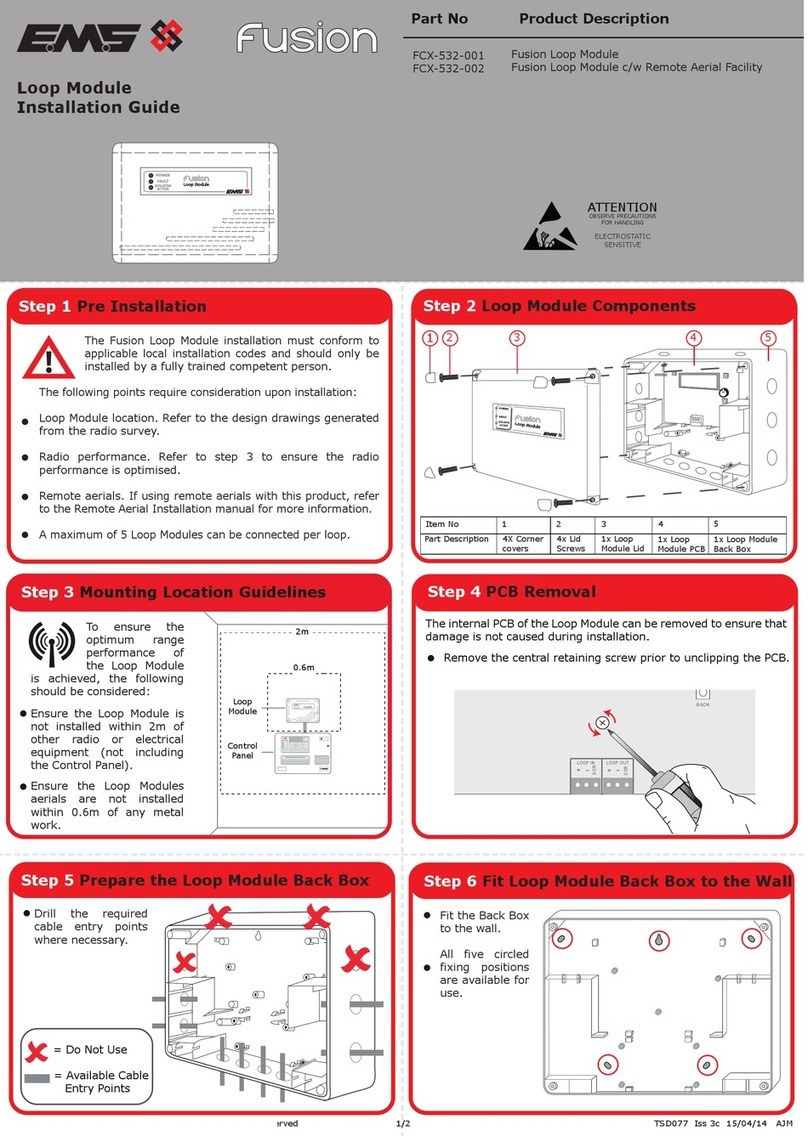
EMS ZITON RADIO LOOP MODULE Owner's manual

EMS
EMS fusion FCX-532-001 User manual

EMS
EMS LRP2000 Series User manual

EMS
EMS FireCell FCZ-170-111 User manual

EMS
EMS ZITON Owner's manual

EMS
EMS FireCellWDC User manual

EMS
EMS Fusion FCX-532-001 User manual

EMS
EMS EC-41-0200 User manual

EMS
EMS FireCell FCZ-170-111 User manual

EMS
EMS EC-41-0200 User manual
Popular Control Unit manuals by other brands

Raita
Raita BioModule Manual Installation

Danfoss
Danfoss iC7 Series installation guide

Digital Equipment
Digital Equipment Pro-face GP-377R Series user manual

Kuppersbusch
Kuppersbusch E5 technical information

ADLINK Technology
ADLINK Technology USB-2405 quick start guide

Pioneer
Pioneer PAC-N10 operating instructions