ENDA ETI741 User manual

ENDA ETI741 TEMPERATURE INDICATOR
TECHNICAL SPECIFICATIONS
ETI741-E-04-R
1/3
* 72 x 72mm sized.
* 4 digits display.
* Selectable sensor type.
* Input offset feature.
* Parameter access protection on 3 levels.
* Programming just by using keypad.
* CE marked according to European Norms.
* Measurement at °C and °F units.
Read this document carefully before using this device. The guarantee will be expired by
damaging of the device if you don't attend to the directions in the user manual. Also we don't
accept any compensations for personal injury, material damage or capital disadvantages.
Sensor type Temperature range
J (Fe-CuNi) Thermocouple
K (NiCr-Ni) Thermocouple
T (Cu-CuNi) Thermocouple
S (Pt10Rh-Pt) Thermocouple
R (Pt13Rh-Pt) Thermocouple
EN 60584
EN 60584
EN 60584
EN 60584
EN 60584
0... 600
0...1200
0... 400
0...1600
0...1600
°C
°C
°C
°C
°C
Accuracy
0,2% (of full scale)
0,2% ( fof ull scale)
1 digit
1 digit
0,2% ( f )of ull scale 1 digit
0,2% ( f )of ull scale 1 digit
0,2% ( f )of ull scale 1 digit
+32... +1112
+32... +2192
+32... +752
+32... +2912
+32... +2912
°F
°F
°F
°F
°F
Pt 100 Resistance Thermometer
Pt 100 Resistance Thermometer
EN 60751
EN 60751
-200...600
-99.9...300.0
°C
°C
0,2% ( f )of ull scale 1 digit
0,2% ( f )of ull scale 1 digit
-328... +1112
-99.9...+543.0
°F
°F
°C °F
ELECTRICAL CHARACTERISTICS
Supply 230V AC +10 -20 , 50/60Hz or 24V AC ±10 , 50/60Hz or optional 9-30V / 7-24V AC SMPS% % % DC ±10%
Power consumption Max. 7VA
2.5mm² screw-terminal connections
Wiring
Line resistance
Data retention
EMC
Safety requirements
EN 61326-1: 1997, A1: 1998, A2: 2001 (Performance criterion B for standard EN 61000-4-3)
EEPROM (minimum 10 years)
EN 61010-1: 2001 (Pollution degree 2, overvoltage category II)
For thermocouple max.100ohm, for 3 wired Pt 100 max. 20ohm
HOUSING
Housing type Suitable for flush-panel mounting according to DIN 43 700.
Dimensions W72xH72xD97mm
Weight Approx. 395g (after packing)
Self extinguishing plastics.
Enclosure material
ENVIRONMENTAL CONDITIONS
Height Max. 2000m
80 up to 31 decreasing linearly 50 at 40 .% %
Ambient/storage temperature
Max. relative humidity
0 ... +50 /-25... +70
°C
°C
°C
°C
Rated pollution degree According to EN 60529 Front panel : IP65
Rear panel : IP20
Do not use the device in locations subject to corrosive and flammable gases.
While cleaning the device, solvents (thinner, benzine, acid etc.) or corrosive materials must not be used.
Thank you for choosing ENDA ETI741 temperature indicator.
TEMPERATURE INDICATOR
ENDA
ETI 741
SET
°F °C
2/3 ETI741-E-04-R
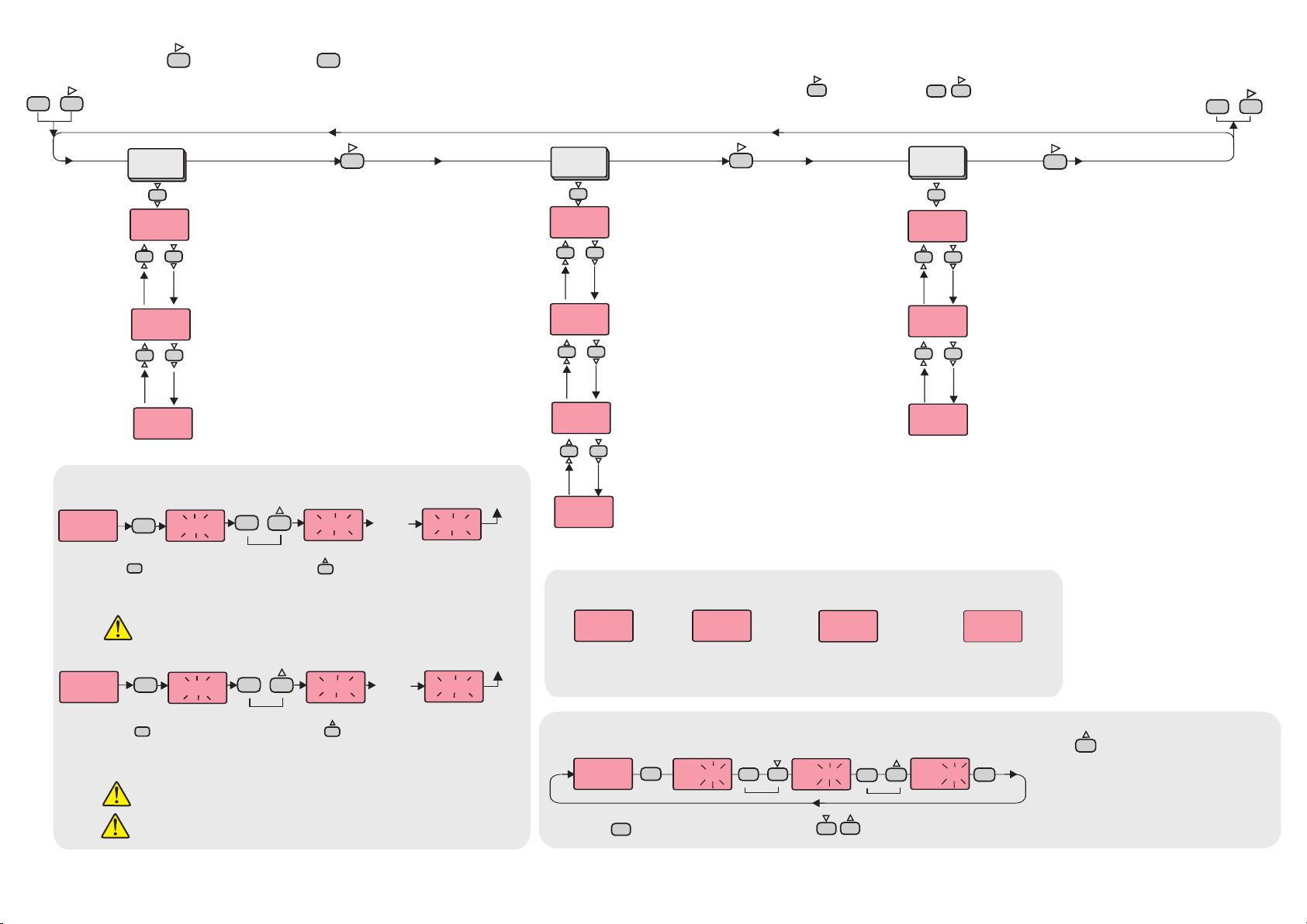
ýnP.
OFFS.
inP. = Type of sensor and scale.
Pt = Pt 100 -200 to +600°C
Pt.0 = Pt 100 -99.0 to +300.0°C
FE.cn. = J (Iron vs. Copper-Nickel) 0 to +600°C
nc.nA. = K (Nickel-Cr.vs. Nickel-Alum.) 0 to +1200°C
c.cn. = T (Copper vs. Copper-Nickel) 0 to +400°C
P10.r. = S (Platinum-10%Rhodium vs. Pt.) 0 to +1600°C
P13.r. = R (Platinum-13%Rhodium vs. Pt.) 0 to +1600°C
S.cod. =
menu access code
It should be 333.
Calibration
rt.CA. =
temperature is calibrated by
this parameter. It is not
displayed if input type is
selected Pt 100.
The environment
tC.CA. =
calibration of thermocouple
input can be made.
(See Note 1 below)
In this case, the
Pt.CA. =
calibration of Pt 100 input
can be made.
(See Note 2 below)
In this case, the
oFFS.=
Offset value is added to the measurement value.
Adjusted between -99 and +99°C.
The normal value is 0.
Offset value.
S.cod.
Rt.CA.
TC.CA.
Pt.CA.
A.Con.
A.CAL.
Before starting calibration procedure, 50.000mV referance voltage must be applied to the
thermocouple inputs.
CAL.
When holding key the message run flashes. In this case if key is pressed, calibration for TC input
starts. Then the messages C.Str, a four digit number and Cal are seen in sequence on the lower display. After 5
seconds End message is seen. If the four digit number is 4999 or 5000 or 5001, it means TC calibration was
successful. Otherwise calibration procedure should be repeated.
SET
SET
SET
press and
hold
NOTE 1
NOTE 2
Before starting calibration procedure, make a connection between terminal 8 and 9. Then connect a
212.052ohm referance resistor should be connected between terminal 9 and terminal 10 or apply 300 °C
from Pt-100 calibrator.
if key is pressed while holding key, the programming mode is enabled.
If key is pressed and held 0.6 seconds,
the value of the selected parameter changes
rapidly. If waited enough, the value
increases 100 at each step. After 1 second
following the release of the key, initial
condition is returned. The same procedure
is valid for the decrement key.
SET
SET
SET
Modification of Parameter
When holding key, the value of parameter flashes and using keys the requested value can be adjusted.
Values on the displays are default values.
When holding key the message run flashes. In this case if key is pressed, calibration for Pt 100
input starts. The messages C.Str, a four digit number and Cal are seen in sequence on the lower display. After
5 seconds End message is seen. If the four digit number is 3190 or 3191 or 3192, this means Pt 100
calibration was successful. Otherwise, Calibration procedure should be repeated.
SET
Entering from the programme mode to the run mode:
Alternatively, the same function occurs first pressing key and then pressing keys together.
If no key is pressed within 20 seconds during programming mode, the data is stored automatically and the normal mode is entered.
SET
UnIt =
Selectable as °C or °F.
The temperature unit.
5 seconds
later
S.cod. =
access code.
It should be 444.
Security menu
A.Con. = Parameters of
configuration menu access level
code.
nonE = Not visible.
P.yES = Visible and modification
can be done.
P. no = Visible and not modified.
A.CAL. = Parameters of
calibration menu access level
code.
no = Not visible
yES = Calibration can be done.
Returns to the normal
operation mode.
SET
SET
SET
SET
SET
Error Messages
Temperature value is
higher than the end
of the scale
Temperature value is
higher than the end
of the scale
Temperature sensor
is broken or
over temperature
Pt 100 or a sensor
line is short circuited
SeCU.
S.Cod.
CAL.
ConF.
UnIt.
Run End.
CAL.
SET SET
Press and
hold
5 seconds
later
Returns to the normal
operation mode
Run End.
TC.CA.
Pt.CA.
----
----
PFA
PSC
HyS.H.
6
5 6

CONNECTION DIAGRAM
3/3 ETI741-E-04-R
ENDA ETI741 is intended for installation in control panels. Make sure that the device is used only for intended
purpose. The installation and electrical connections must be carried on by a qualified staff and must be according
to the relevant locally applicable regulations. During an installation, all of the cables that are connected to the
device must be free of energy. The device must be protected against inadmissible humidity, vibrations, severe
soiling and make sure that the operation temperature is not exceeded. All input and output lines that are not
connected to the supply network must be laid out as shielded and twisted cables. These cables should not be
close to the power cables or components. The shielding must be grounded on the instrument side.
For J-K-T-S-R type thermocouple :
Use suitable compensation cables. Don't use
jointed cables. Pay attention to the polarities of the
thermocouple cables as shown in the figure right.
SENSOR INPUT :
TC
-
+
-
+
For resistance thermometer :
When 2 wired Pt 100 is used,
terminals 8 and 9 must be
short circuited.
9
10
9
Pt 100
10
8
1) Mains supply cords shall meet the requirements of IEC 60799
or IEC 60245.
2) In accordance with the safety regulations, the power supply
switch shall bring the identification of the relevant instrument
and it should be easily accessible by the operator.
Note :
NOTE :
Fuse should
be connected.
184-253V AC
50/60Hz 7VA
230V AC Supply
switch
Cable size: 1,5mm²
Fuse
F 100 mA 250V AC
Neutral
Line
SUPPLY :
12
11
Holding screw 0.4-0.5Nm
Equipment is protected througout
by DOUBLE INSULATION.
Order Code : ETI741-
1
Supply Voltage
230VAC...230V AC
24VAC.....24V AC
SM...........9-30V DC / 7-24V AC
Depth
97mm
2
Panel cut-out 75mm
84mm
68 mm
+0.7
68 mm
+0.7
72mm
78mm
TEMPERATURE INDICATOR
ENDA
ETI 741
SET
°F °C
Temperature
compansation sensor
2
Note 1) While panel mounting, additional distance required
for connection cables should be considered.
2) Panel thickness should be maximum 10mm.
3) If there is no 90mm free space at back side of the device,
it would be difficult to remove it from the panel.
- Push the flush-mounting
clamp in direction 1as
shown in the figure left.
- Then, pull out the clamp in
direction 2.
For removing mounting clamps:
Connection
cables
Rubber packing
Flush mounting
clamp
Panel
1
1
DIMENSIONS
SN: XXXXXXXXX
ENDA INDUSTRIAL ELECTRONICS
ETI741-230VAC
TEMPERATURE INDICATOR
11
12
230V AC +10% -20%
50/60Hz 7VA
TC
+
-
Pt 100
8
9
10
This manual suits for next models
1
Other ENDA Measuring Instrument manuals


Popular Measuring Instrument manuals by other brands

Pyxis
Pyxis ST-525 user manual

Rosemount
Rosemount 5401 Reference manual

Pulsar
Pulsar Pulsarguard 201 Series instruction manual

Badger Meter
Badger Meter ORION SE Installation data

E Instruments
E Instruments E4500 operating & maintenance manual

Ronan Engineering
Ronan Engineering X76CTM series Instructions and operating manual

Emerson
Emerson ControlWave Series Site Considerations for Equipment Installation, Grounding, and Wiring Manual

Inepro
Inepro DZT 6252 Short manual

AnyNet
AnyNet ANY-CMS-4M Operation manual

RS PRO
RS PRO RS-135 instruction manual

Gossen MetraWatt
Gossen MetraWatt METRISO C operating instructions

Omega
Omega Vortex FV100 Series user guide


