Endo EDB-50 User manual

For safe and correct operation of the product, please be sure to read this manual and fully
understand its content before use.
After reading, keep the manual safe so that you can find and use it readily.
In case of resale or transfer, make sure to transfer the manual to the new owner.
Users Manual
Magical Balancer
EDB-50
/
EDB-85
/
EDB-130
HMU- 2d
Issued in September 2 21

Magical Balancer Introduction
1
Introduction
Thank you very much for purchasing the Magical Balancer main equipment (also referred to
as the product). To resolve any trouble and obtain the best performance from the product, please be
sure to read this Instruction Manual (hereafter referred to as the manual) and fully understand its content.
Notation in this manual
Hazard le els
This product is designed with ultimate priority on the safety of operators. However, due to the
nature of the system, there are risks that cannot be removed.
In this manual, the level of significance and risk is defined and indicated in four stages, “DANGER”,
“WARNING”, and “CAUTION”. Thoroughly read and fully understand the indicated items before
operating the product and performing maintenance procedures. The indications for “DANGER”,
“WARNING”, and “CAUTION” are described below in order of risk significance (DANGER >
WARNING > CAUTION).
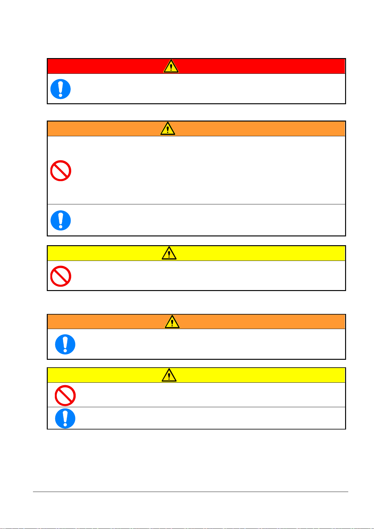
DANGER Indicates a situation that, if mishandled, causes a danger of serious
injury or death.
WARNING Indicates a situation that, if mishandled, may cause serious injury or
death.
CAUTION Indicates a situation that, if mishandled, may cause injury or property
damage.
NOTICE
Indicates a situation that, if mishandled, may cause property damage.
The extent of the problem described above (disability, injury, and property damage) is defined as follows.
Serious disability: Loss of eyesight, wound, burn (high-temperature or low-temperature), electric
shock, bone fracture, poisoning, and other injuries that leave aftereffects and
that require hospitalization or long-term outpatient treatment.
Moderate injury: Burn, electric shock, bone fracture, and other injuries that do not require
hospitalization or long-term outpatient treatment.
Minor injury: Scratch, bruise, laceration, and other injuries that have a minor impact on health.
Property damage: Extended damage to buildings, household articles, and injury to domestic
animals or pets.
Symbols
This Instruction Manual uses the following symbols that simply describe warning information in
addition to the indications above, “WARNING” and “CAUTION”.
Indicates a PROHIBITED action that must not be performed.
Indicates potential property damage or a danger that may inflict bodily injury.
Indicates a REQUIRED action that must be performed.
Indicates a NOTES when operating and maintaining the equipment.
Indicates that it is necessary to thoroughly read this manual and the relevant
documents.

Magical Balancer Introduction
2
Scope of warranty and liabilities for the equipment
Warranty and liabilities for the equipment
1. We will repair or replace the product free of charge if a failure due to manufacturing defects
occurs under proper usage during the warranty period. In this case, present your warranty and
request repair from your dealer.
2. The warranty will be void in the following cases:
1) Change in ownership.
2) Repair adjustment, or modification performed by a party other than the manufacturer,
agents, or dealers.
3. The warranty period is one (1) year from the date of purchase.
4. Repairs applicable to any of the following shall be charged even during the warranty period:
1) Failure/damage caused by incorrect use.
2) Failure/damage caused by use of non-genuine parts.
3) Failure/damage caused by fire, earthquake, natural disaster, or other unexpected incident.
4) Incident caused by fall, shock, negligence, or by inadequate storage.
5) Failure/damage caused by use of parts or other equipment that are not included in this
product.
6) Replacement of consumables.
7) Usage in violation of dangers or cautions stipulated in this manual.
8) Failure/damage caused by any reason that is not attributable to the manufacturer.
5. Warranty exclusions such as opportunity loss.
Excluded from the warranty period are opportunity loss, damage to anything other than our
product(s), or other duties placed on you/your customers as a result of the failure of our
product(s).
Copyright and liabilities
The copyright for this Instruction Manual (included with the product) belongs to Endo Kogyo
Co.,Ltd.
The Instruction Manual is provided for the limited purpose of supporting the safe and proper use of
the product. It cannot be used for other purposes.
The customer may not use or make copies of this manual, in whole or in part, outside of this
purpose without receiving prior consent from Endo Kogyo Co., Ltd.
The customer is also prohibited from translating or modifying the content of the manual,
in whole or in part.
The content described in the manual is subject to change without advance notice.

Magical Balancer Introduction
3
Definition of intended users for this manual
This manual has been prepared to help all intended users involved with this product. From the
point of view of safety, we have defined intended users according to their ability and experience
and provided detailed descriptions for each group.
This manual defines four user levels.
Operator
The operator is a user who engages in general operations. Maintenance and other operations that
require special skills are excluded from the general operations.
The operator is therefore not permitted to disassemble, install, or assemble the product.
The operator should read the manual thoroughly and carry out their work with complete
understanding of the operating procedures.
Maintenance operator
In addition to the work of the operator described above, the maintenance operator is permitted to
perform installation, simple troubleshooting, and periodic inspections.
The maintenance operator is required to have develop sufficient knowledge and operating skill for
this product. The maintenance operator should read the manual thoroughly and carry out their
work with a complete understanding of the equipment’s characteristics and all required work.
Management super isor
Duties of the management supervisor include turning ON/OFF the power when the work is
completed and performing safety checks using an electroscope as necessary.
The management supervisor is required to have sufficient knowledge of the product and advanced
operating skill for this product.
The management supervisor should manage not only the product itself but on-site operations that
handle the product, comprehensively.
Ser ice engineer
A worker with special knowledge and skills for installing the product, investigating the causes of a
failure or damage, and performing repairs and overhauls.
Service engineering is normally performed by our service technicians
Emergency contact in case of malfunctions
If any malfunction occurs with the product, refer to the contact information indicated on the back
cover of this manual and contact Endo Kogyo or an authorized dealer.
Our service representative will assist you.

Magical Balancer CONTENTS
4
CONTENTS
Introduction ............................................................................................. 1
Notation in this manual ........................................................................................... 1
Hazard levels ...........................................................................................................................1
Symbols ...................................................................................................................................1
Scope of warranty and liabilities for the equipment ............................................ 2
Warranty and liabilities for the equipment ...............................................................................2
Copyright and liabilities ............................................................................................................2
Definition of intended users for this manual ........................................................ 3
Emergency contact in case of malfunctions ........................................................ 3
1. Warning sign and Precautions for Handling ..................................... 7
1-1 Labels and name plates ............................................................................. 7
1-1-1 Types of warning labels and nameplates ...................................................................7
1-1-2 Locations of warning labels and nameplates .............................................................9
1-2 Precautions for handling ......................................................................... 10
1-2-1 General handling ......................................................................................................1
1-2-2 Installation ................................................................................................................ 11
1-2-3 Air supply pressure and voltage ............................................................................... 11
1-2-4 Pewcautions for use .................................................................................................12
1-2-5 Periodic inspections .................................................................................................14
2. Unpacking and Installation ............................................................... 15
2-1 Packaging arrangement and transportation .......................................... 15
2-2 Checks after unpacking ........................................................................... 15
2-2-1 Set of product ...........................................................................................................15
2-2-2 Record of product .....................................................................................................16
2-2-3 Prerecording for inspection .........................................................................................16
2-3 Disposal of packing materials ................................................................. 16
3. Product Description .......................................................................... 17
3-1 Summary of Magical Balancer ................................................................ 17
3-1-1 Functions of Magical Balancer .................................................................................17
3-2 Components .............................................................................................. 18
3-2-1 Appearance of the mainequipment of the Magical Balancer ...................................18
3-2-2 Names and functions of the control panel section of the grip box and the bottom of the
control box of the main equipment ........................................................................................19
3-3 Product specifications ............................................................................. 20
3-4 Operating en ironment ............................................................................ 20
3-5 Disposal of the product ........................................................................... 20
4. Installation of Magical Balancer ....................................................... 21
4-1 Preparation and required checks before installation ............................ 21

Magical Balancer CONTENTS
5
4-1-1 Tools for installation ..................................................................................................21
4-1-2 Check of installation location ....................................................................................21
4-2 Installation procedures ............................................................................ 22
4-2-1 Installation ................................................................................................................22
4-3 Attachment of the upper hook(standard accessories) .......................... 23
4-4 Attachment of trolley (special accessories) ........................................... 24
4-5 Piping of the air hose ............................................................................... 25
4-6 Connection of the power cable ............................................................... 26
4-7 Post-installation checks .......................................................................... 26
4-7-1 Checking the winding up operation ..........................................................................26
4-7-2 Checking the working range .....................................................................................26
4-7-3 Other checks ............................................................................................................26
5. Usage of Magical Balancer ............................................................... 27
5-1 Iinspections before starting the operation ............................................. 27
5-1-1 Checking before starting up .....................................................................................27
5-1-2 Checking the operation with an empty load .............................................................27
5-1-3 Checking the operation with a load ..........................................................................27
5-2 Starting up the Magical Balancer ............................................................ 28
5-3 Controlling the Magical Balancer ............................................................ 28
5-3-1 Control mode ............................................................................................................28
5-3-2 How to suspend a load .............................................................................................29
5-3-3 Balancing mode ........................................................................................................29
5-3-4 How to lift down the load ..........................................................................................29
5-3-5 Function button .........................................................................................................29
5-4 Operations after completing the work .................................................... 30
5-5 Storing the magical balancer................................................................... 30
5-6 Mode menu ............................................................................................... 31
5-6-1 Switching the mode menu ........................................................................................31
5-7 Function button settings ......................................................................... 32
5-8 Setting No-Load Weight using select switch (Option) .......................... 33
6. Periodic Inspections and Maintenance ........................................... 34
Monthly inspection ...................................................................................................35
Operating limit of the parts .......................................................................................35
6-1 Lubrication ................................................................................................ 35
6-1-1 Lubrication for the main equipment of the Magical Balancer...................................35
6-2 Inspection methods ............................................................................... 36
6-2-1 Inspection of the hooka and their operating limit .....................................................36
Inspection of the opening, inspection for cracking and wear, and the operation limit36
Dimensions of the opening and the limit on the wear amount ................................36
6-2-2 Inspection of the wire rope and its operating limit ....................................................37
Limits on the wire breakage and the wear amount .................................................37
Inspection of the diameter of the wire rope .............................................................37

Magical Balancer CONTENTS
6
Wire rope end .........................................................................................................38
6-2-3 Inspection main equipment ......................................................................................38
6-2-4 Inspection of the control module ..............................................................................38
6-2-5 Other inspections .....................................................................................................38
Labels and tags ........................................................................................................38
Trolley ......................................................................................................................38
Support members ....................................................................................................38
Power cable .............................................................................................................38
6-2-6 Comprehensive operation inspection .......................................................................39
Operation with a load ...............................................................................................39
7. Troubleshooting ................................................................................ 40
7-1 Main failures and countermeasures ....................................................... 40
7-2 Error Mode ................................................................................................ 41
7-2-1 Operation method of the Error Mode .......................................................................41
7-2-2 Error in the control box and the countermeasures...................................................42
7-2-3 Error in the grip box and the countermeasures .......................................................43
8. Dimensional Drawing ........................................................................ 44
EDB-5 .....................................................................................................................44
EDB-85.....................................................................................................................45
EDB-13 ..................................................................................................................46

Magical Balancer 1 Warning sign and Precautions for Handling
7
1. Warning sign and Precautions for Handling
1-1 Labels and name plates
Warning labels are attached to the locations with potential dangers related to the operation and
maintenance.
The warning labels are displayed in an appropriate size and color that can easily attract operators’
attention and indicate warning information and symbols of hazard classification.
In addition to the warning labels, handling labels that provide the information necessary for
handling and nameplates that provide the product information are attached to the product.
CAUTION
The operators must check the positions of all danger warning labels attached to
the product, and thoroughly read and fully understand the information on the
labels before performing any procedure.
If the warning labels or the nameplates are peeling off or deteriorated and
become illegible, contact us to replace them.
1-1-1 Types of warning labels and nameplates
The following labels are attached to this product.
No.
Label appearance Details
Ⓐ
N
d
s
e
o
u
v
s
e
n
p
o
e
r
t
n
r
d
e
s
i
m
o
n
o
g
i
v
l
e
a
i
t
t
lo
h
.
a
is
d .
p la te o r
Ne ve r u se f
lo wer in g pe
o
o
r
p le
l
.
ift ing o r
Ne ve r o per a te o ve
Ne ve r li ft a lo ad
r
g
p
r
e
e
o
a
p
te
le
r
.
Ne ve r o per a te w it h k ink
de fo rme d, o r b rok e n w ir
e
e
d,
ro pe .
Ne ve r
o r a b n
o
o
p
rm
er
a
a
l
te
so
w
u
h
n
e
d
n
/
dam age d
vib rat io n o ccu rs .
ju s t un de r the A ir Ba lan
be fo re o pe ra tion .
ce r
Ne ve r remo ve a lo a
h andl ing equ ipm en t
d
u
o
n
r
t
the w ire ro pe i s s lac ke
i
d
l
.
tha n m ax imum c ap ac ity .
hec k the lo ad is
a pp lie d to the hoo k
co
a
r
n
r
d
ect ly
Ne ve r le ave dur in g
o
Re
pe
ed
rat
th
io
i
n
s
.
m anua l be fo re
This label is a warning label attached to the
main equipment of the Magical Balancer.
Cautions for handling the product are
indicated.
Ⓑ
This is a nameplate attached to the main
equipment of the Magical Balancer. The model
name, serial number, and specifications of the
product are indicated.

Magical Balancer 1 Warning sign and Precautions for Handling
8
No.
Label appearance Details
Ⓒ
This is a nameplate attached to the control box
of the main equipment of the Magical Balancer.
The model name and serial number of the
stand-alone control module are indicated.
Ⓓ
This label is a warning label attached to the
control box of the main equipment of the
Magical Balancer.
This is a warning label against electric shock.
Ⓔ
This tag is attached to the curled cord.
Cautions for handling the product are
indicated.
Ⓕ
Status lamp
状態ランプ
This label is attached to the control box of the
main equipment of the Magical Balancer.
This label shows the operating conditions.
Ⓖ
release button
Emergency
非常下降ボタン
This label is attached to the control box of the
main equipment of the Magical Balancer.
This label shows the emergency release
button.
Ⓗ
This label is the error code table attached to
the control box of the main equipment of the
Magical Balancer.
This label shows the error code numbers and
the error names.
Magical Balancer 1 Warning sign and Precautions for Handling
9
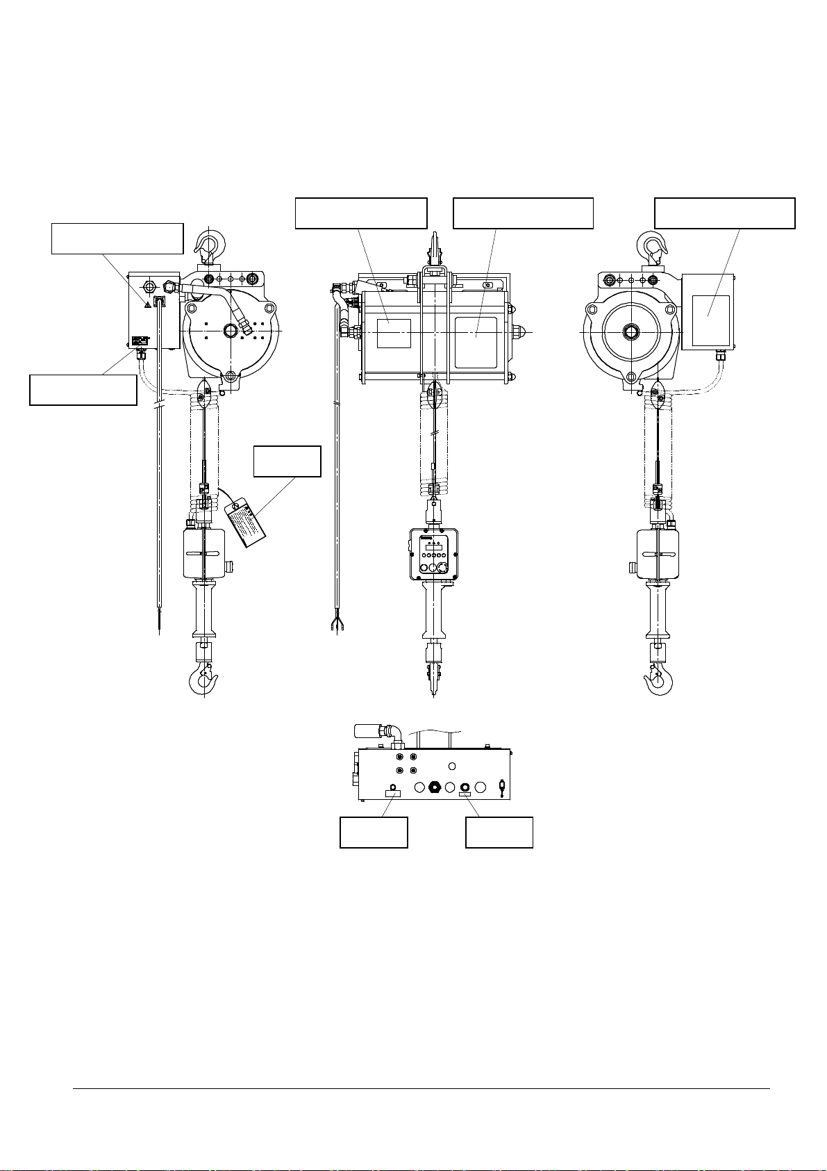
1-1-2 Locations of warning labels and nameplates
The labels and nameplates are attached to the following locations of the product as shown below.
ⒺTag
ⒶWarning Label ⒷName Plate
ⒹWarning Label
ⒸName Plate
ⒼLabel ⒻLabel
ⒽError Code Table

Magical Balancer 1 Warning sign and Precautions for Handling
1
1-2 Precautions for handling
Incorrect handling of this product may cause damage to the product or the suspended load as well
as an injury.
Thoroughly read the following precautions and be sure to observe them when handling the
product.
1-2-1 General handling
DANGER
Do not mo e directly under a lifted load.
Do not transport a load o erhead.
WARNING
Do not use the product for lifting or transporting a person.
Do not lift or transport a load o erhead or near a person.
A person who has not recei ed education (training) in the safety and the operation
must ne er (and must ne er be permitted to) operate the Magical Balancer or perform
slinging work.
Do not operate the Magical Balancer when your health makes you unable to perform
operation adequately.
A person who operates the balancer should ha e no difficulties in hearing or ision,
and needs to ha e deep expertise.
When a sign such as “Inspection in progress” or “Do not operate” is attached to the
grip controller of the Magical Balancer, do not operate the Magical Balancer until a
designated person remo es the sign.
Before the installation, operation, or maintenance and inspection of the product,
carefully read and understand this Instruction Manual, and correctly use the product
in order to a oid accidents from mishandling.
Store this Instruction Manual so that anyone who performs the installation, operation,
or management of the product can use it.
For support members to attach (suspend) the Magical Balancer, use members that
ha e a sufficient safety coefficient for supporting the mass (weight) and the
maximum capacity of the Magical Balancer.
Be sure to perform inspections before starting the operation as well as periodic
inspections.
Magical Balancer 1 Warning sign and Precautions for Handling
11
1-2-2 Installation
DANGER
Be sure to install the stoppers on the ends of the tra erse and tra el rails.
Ensure that the location where the Magical Balancer is installed has sufficient
strength.
WARNING
The installation must be performed by professionals or a person who has expertise.
Do not install the Magical Balancer in a location outside the specified en ironment,
such as a location where the balancer is exposed to rain or water.
Do not connect the ground wire to the following.
Gas and hydraulic piping: Danger of explosion or catching fire.
Telephone line and lightning rod: Danger in case of lightning.
Water pipe partially made of plastic in the middle: Does not ser e as the ground.
Danger of electric shock. Implement a D class grounding construction.
In addition to the grounding, install an earth leakage breaker on the electric circuit.
Be sure to attach an auxiliary wire rope to the Magical Balancer.
CAUTION
Do not operate the product on the floor (placed horizontally).
Do not operate the Magical Balancer with slack in its wire rope.
Always suspend the balancer when operating it.
1-2-3 Air supply pressure and oltage
WARNING
Operate the Magical Balancer with an air supply pressure less than 0.7 MPa.
Use the operating oltage and current within their ratings
(AC100V/0.7A・AC115V/0.7A・AC240V/0.4A)
CAUTION
Do not use a lubricator (oiler) for the air supply line of the Magical Balancer.
Do not use any type of lubricating oil, because it may cause a malfunction in the
control module as well as damage to the internal parts.
Be sure to install a filter and a regulator.

Magical Balancer 1 Warning sign and Precautions for Handling
12
1-2-4 Pewcautions for use
DANGER
Do not mo e directly under a lifted load.
Do not transport a load o erhead.
Ne er operate the product if the following abnormalities exist in the wire rope.
(1) Kink, deformation, or corrosion
(2) Wire breakage, wear beyond the usage limit
WARINNG
Ne er suspend a load exceeding the maximum capacity.
Note: The maximum capacity is indicated on the main equipment.
Do not permit a person to climb on the suspended load. In addition, ne er use the
product for carrying a person.
Do not enter the tra eling direction (path) of the suspended load.
Do not mo e your face close to the suspended load.
Do not operate the balancer while putting your hand or finger in the hook.
Do not operate the balancer when there is a person within the range of mo ement
of the suspended load.
Do not lea e the operating position while suspending a load.
Do not operate the balancer in such a way that the suspended load or the bottom
hook will swing.
Do not use the stoppers to stop hoisting of a load.
Do not pull a load in an oblique direction.
When the bottom hook is not located directly under the Magical Balancer, do not
operate the Magical Balancer.
Mo e the Magical Balancer directly o er the center of gra ity of the load before
suspending it.
Pre ent the wire rope from contacting with a sharp edge.
A oid lifting a load fixed to another structure.
Do not perform re ersing of the suspended load.
Check the operation of the grip controller before use. Do not operate the balancer
if the grip controller does not operate smoothly.
Do not operate the Magical Balancer if it is damaged or it creates abnormal noise
or ibration.
Do not se er a load suspended in midair.
Do not electrically weld a load suspended in midair.
Do not connect the ground of a welder to the wire rope.
Ne er allow the wire rope to contact with a welding electrode.

Magical Balancer 1 Warning sign and Precautions for Handling
13
WARNING
Use the operating oltage and current within their ratings.
When mo ing the Magical Balancer, ensure that there is no obstacle within the
range of mo ement of the suspended load and the hook.
Always pay attention to the load while operating the balancer.
If the balancer mo es opposite to the slide direction of the grip controller, stop the
operation immediately.
To mo e a load with the plain trolley, do not push the wire rope of the Magical
Balancer, but push the load.
Do not pull the load.
CAUTION
Ne er use the product if the hook latch is damaged or not functioning normally.
Do not operate the balancer rapidly, for example, by lifting a load up and down
rapidly or stopping suddenly.
Do not use the product while holding a stopper.
Pre ent the suspended load from contacting with the wiring and other structures.
Do not hang the curled cord on other objects or pull the cord hard.
Pre ent the Magical Balancer or the trolley from colliding with the stopper of the
I-shaped steel (rail) or other structures.
Do not wind up the wire rope rapidly when slack remains in the rope.
Ensure that the lifting height is sufficient for the work.
Do not lea e a load suspended.
The suspended load may slowly descend o er time. After the work is completed,
lift down the suspended load to the ground.
Do not shut off the power supply or the air supply when the load is suspended.
Smoothly perform the lifting up and down of the suspended load.
Ensure that the bottom hook can rotate smoothly before use.
Correctly place the sling on the hook.
Stop winding up temporarily after the wire rope is tightened.
Note: Do not rapidly hoist the load from the ground.
If the air supply pressure is shut off while the product is being used, the load is
held temporarily and then slowly descends o er time.
If you cannot lift down the load due to the winding limit of the wire rope, manually
pull out the wire rope to lift down the load.

Magical Balancer 1 Warning sign and Precautions for Handling
14
1-2-5 Periodic inspections
DANGER
Periodically inspect the Magical Balancer, and replace worn or damaged parts.
Discard the hook if it is stretched, worn or damaged.
Do not try to repair it, but replace with a new hook.
WARNING
Ne er perform any modification of the product or its accessories.
Ne er use parts other than our genuine parts.
Before performing maintenance and inspection or repair, shut off supply of the
air and electricity.
The maintenance and inspection or repair must be performed by a person with
expertise designated by the business operator.
Always perform the maintenance and inspection or repair with an empty load
(without a load).
Be sure to lift down the Magical Balancer to the ground before disassembling it.
If any abnormal part is found during the maintenance and inspection, do not use
the product as is, but repair it immediately.
When performing the maintenance and inspection or repair, be sure to post a
sign indicating that the work is in progress (such as “Inspection in progress”
and “Do not operate”).
If there is anything unclear regarding the Magical Balancer, stop using it and
contact us or the agent from which you purchased the product.
CAUTION
Follow the instructions (see “エラー! 参照元が見つかりません。 エラー! 参照元が見
つかりません。”) to perform lubrication.
When performing a test run after the maintenance and inspection or repair, be
sure to perform it with the Magical Balancer suspended.
Note: Do not operate the Magical Balancer with slack in its wire rope.

Magical Balancer 2 Unpacking and Installation
15
2. Unpacking and Installation
2-1 Packaging arrangement and transportation
This product is packaged for delivery in a cardboard box.
The total weight of the package is approximately 42 kg and 5 kg or more for the light and heavy
models, respectively.
When transporting the package, use a dolly or lifter, and do not drop or apply excessive impact to
the package.
Prepare a box of a similar size for re-packaging.
2-2 Checks after unpacking
After opening the package, check that the ordered items are included.
Please contact us if by any chance you find anything missing or damaged.
2-2-1 Set of product
No.
Item name Quantity
Appearance
① Main equipment
1
② Set of wire rope
③ Control module
Model: EPG
④ Upper hook
⑤ Power cable
⑥ Set of support
wire rope 1
⑦ Instruction Manual
(this manual) 1
Notes:
• The figure above is an image intended to help explain the names. The dimensions and shapes differ
according to the specifications.
• Items (2) to (5) are delivered as the standard accessories and assembled in the main equipment
before shipment.
Magical Balancer 2 Unpacking and Installation
16
2-2-2 Record of product
Record the model (MODEL) and the serial number indicated on the nameplate of the product
as well as your dealer.
Note: When you request repair or need consumable parts, contact us after preparing this type of
information in advance.
Item Product information
Product model
Serial number of main equipment
Serial number of control module
Date of purchase
Dealer
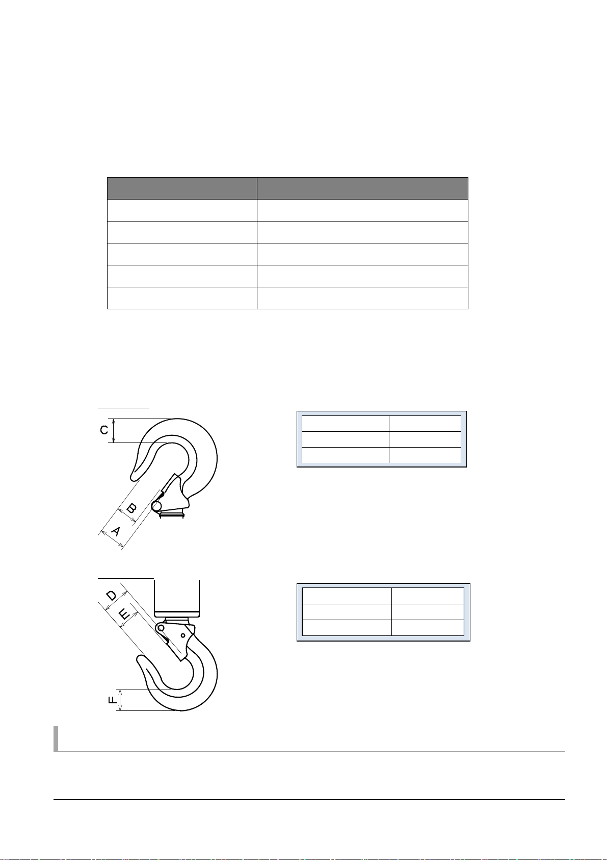
2-2-3 Prerecording for inspection
After purchasing the product, measure and record the actual dimensions of the hooks in
advance, and use the measured values as the references for inspection.
Upper hook
Bottom hook
2-3 Disposal of packing materials
After opening the package, dispose of any packing and cushioning materials in accordance with
the municipal regulations in the area where the product is used.
Measurement A
mm
Measurement B
mm
Measurement C
mm
Measurement D
mm
Measurement E
mm
Measurement F
mm

Magical Balancer 3 Product Description
17
3. Product Description
3-1 Summary of Magical Balancer
3-1-1 Functions of Magical Balancer
The Magical Balancer EDB series models are hoisting machines operated with compressed air
and air cylinders. The balancers can be used for cargo handling and transportation.
The piston is pushed out by the air supply and rotates the drum, thereby winding up the wire rope
around the drum.
When the air is released, the wire rope is reeled out by the self weight of the bottom hook and the
load.
The supply and release of the air are controlled with electrical signals.
エア供給
シリンダ
ワイヤロープ
ド ラ ム
上昇
下フック
ピスト ン
下降
エア開放
In addition, the product is equipped with a “anti-jump device”, which uses a ratchet mechanism to
prevent the suspended load from rebounding due to rapid winding after the load is dropped.
Springs out with
the centrifugal force
Drum Piston
Cylinder
Air
Air
Down
Up
Wire rope
Bottom
hook

Magical Balancer 3 Product Description
18
3-2 Components
3-2-1 Appearance of the mainequipment of the Magical Balancer
The names of main components of magical balancers are provided below.
(The numbers in the figure below are intended to help explain the names. Please note that they
are different from the numbers in the Parts List.)
Notes: • The figure above is an image intended to help explain the names. Since the dimensions and
shapes differ according to the specifications, refer to the attached Exploded View and Parts List
for the details.
• The set of the control section including the control box of the main equipment, curled cord, and
grip controller are together referred to as the control module.
Code Name Code Name Code Name
1 Casing 7 Wire rope 13 Control box of main
equipment
2 Hanger 8 Wire clip 14 Power cable
3 End cap 9 Grip controller 15 Curled cord
4 Air supply port 1 Grip box 16 Upper hook
5 Wire guide 11 Grip 17 Auxiliary wire rope
6 Stopper 12 Bottom hook

Magical Balancer 3 Product Description
19
3-2-2 Names and functions of the control panel section of the grip
box and the bottom of the control box of the main equipment
The following are the names and functions of the control panel section of the grip box and the
bottom of the control box of the main equipment.
(The numbers in the figure below are intended to help explain the names. Please note that they
are different from the numbers in the Parts List.)
No.
Name Function
1 Power switch Used to start up and shut down the Magical Balancer.
2 Grip lamp Turns ON in green during the grip control.
3 Work lamp Turns ON in blue during the workpiece control.
4 Alarm lamp Turns ON in red when an abnormality has occurred.
5 LCD display The statuses of the equipment, any errors that are occurring, etc. are
displayed.
6 [Mode] key Used to select the display mode shown on the LCD indicator.
7 [Set] key Used to confirm the displayed content or configure the settings.
8 [Shift] key Used in combination with the [Set], [
△
], and [▼] keys.
9 [
△
] key Used to increase the displayed numerical value (+1) or shift the displayed
content upward.
1
[▼] key Used to decrease the displayed numerical value (-1) or shift the displayed
content downward.
11
Function button Pressing down this button during the workpiece control disables the
balancing mode and maintains the position of the suspended load even
when the load fluctuates. However, this function cannot be used when the
load fluctuation occurs instantaneously.
The functions of this buttons can be changed by parameter settings.
12
Emergency
stop button
Pressing down this button stops the Magical Balancer by shutting off the
air inside. In addition, the grip control mode as well as the balancing mode
are disabled.
13
Status lamp Turns ON while the equipment is operable, and blinks when an abnormality
has occurred.
14
Control box buzzer Sounds when the mode is switched to the balancing mode.
15
Emergency release
button
If the balancer become inoperable, for example, when a power failure has
occurred, pressing this button evacuates the air inside the cylinder,
allowing the suspended workpiece to slowly descend and be released.
This manual suits for next models
2
Table of contents
Other Endo Wheel Balancer manuals


