Eneo APB-6SV2812MVA User manual

Installation Guide
1/3” Camera, Day&Night, Eo-V,
2.8~12mm, 750TVL, WDR, Infrared, 12/24V, IP67
APB-6SV2812MVA
EN


Safety Precaution
03
ULTRA CLEAR RESOLUTION CAMERA
CAUTION: TO REDUCE THE RISK OF ELECTRIC SHOCK,
DO NOT REMOVE COVER (OR BACK).
NO USER SERVICEABLE PARTS INSIDE.
REFER SERVICING TO QUALIFIED SERVICE PERSONNEL.
To prevent fire or shock hazard, do not expose the unit to rain or moisture.
To prevent electric shocks and risk of fire hazards, do NOT use other than
specific power source.
Warning :
This equipment has been tested and found to comply with the limits for a Class
A digital device, pursuant to part 15 of the FCC Rules. These limits are designed
to provide reasonable protection against harmful interference when the equipment
is operated in a commercial environment. This equipment generates, uses, and
can radiate radio frequency energy and, if not installed and used in accordance with
the instruction manual, may cause harmful interference to radio communications.
Operation of this equipment in a residential area is likely to cause harmful
interference in which case the user will be required to correct the interference at
his own expense.
Caution :
Any changes or modifications in construction of this device which are not expressly
approved by the party responsible for compliance could void the user's authority
to operate the equipment.
Mains power quality should be that of a typical commercial environment. If the user
of the model requires continued operation during power mains interruptions, it is
recommended that the model be powered from an uninterruptible power supply
(UPS) or a battery.
The symbol is intended to alert the user to the presence of important
operating and maintenance(servicing) instructions in the literature
accompanying the unit.
The symbol is intended to alert the user to the presence of uninsulated
"dangerous voltage" within the product's enclosure that may be of
sufficient magnitude to constitute a risk of electric shock to persons.

ULTRA CLEAR RESOLUTION CAMERA
Safety Precaution
04
NOTICE
The image used in this instruction manual are processed to help comprehension
and may differ from actual video of the camera.
Avoid installing areas where has shock or vibration which results in the problems.
Pay attention to safety when laying the connection cable and observe that the cable
is not subjected to heavy loads, kinks or damage and no moisture can get in.
Never open the device such as boards or lens.
The warranty becomes void if repairs are undertaken by unauthorized persons.
Maintenance and repair have to be carried out only by authorized service centers.
Use only a mild detergent to clean the housing.
The camera should never be operated beyond the technical specifications.
This can lead to destruction.
The camera should never be operated in water.

ULTRA CLEAR RESOLUTION CAMERA
Contents
05
Safety Precaution
p.03~04
Contents
p.05
Features
p.06
Composition
p.07
Dimensions
p.07
Part Names
p.08
Installation Instructions
p.09~11
Operating Instructions
p.12~31
Specifications
p.32

ULTRA CLEAR RESOLUTION CAMERA
Features
Key Features
General Description
06
• 1/3” High density Sony CCD (960H)
• 750TVL High-Resolution
• True WDR (Wide Dynamic Range)
• TDN with Dual Filter Switcher
• Built-in f=2.8~12mm F1.4 Mega pixel DC Auto Iris vari-focal lens
• Improved noise reduction 2D+3DNR
• Improved IR-Optimizer
• DIS(Digital Image Stabilizer), LSC (Lens shading compensation)
• Scene Preset, Motion detection, Polygon privacy mask(up to 15)
E-Zoom, Defog, Sens-up, BLC/HLC, Flickerless, Anti-CR, Flip
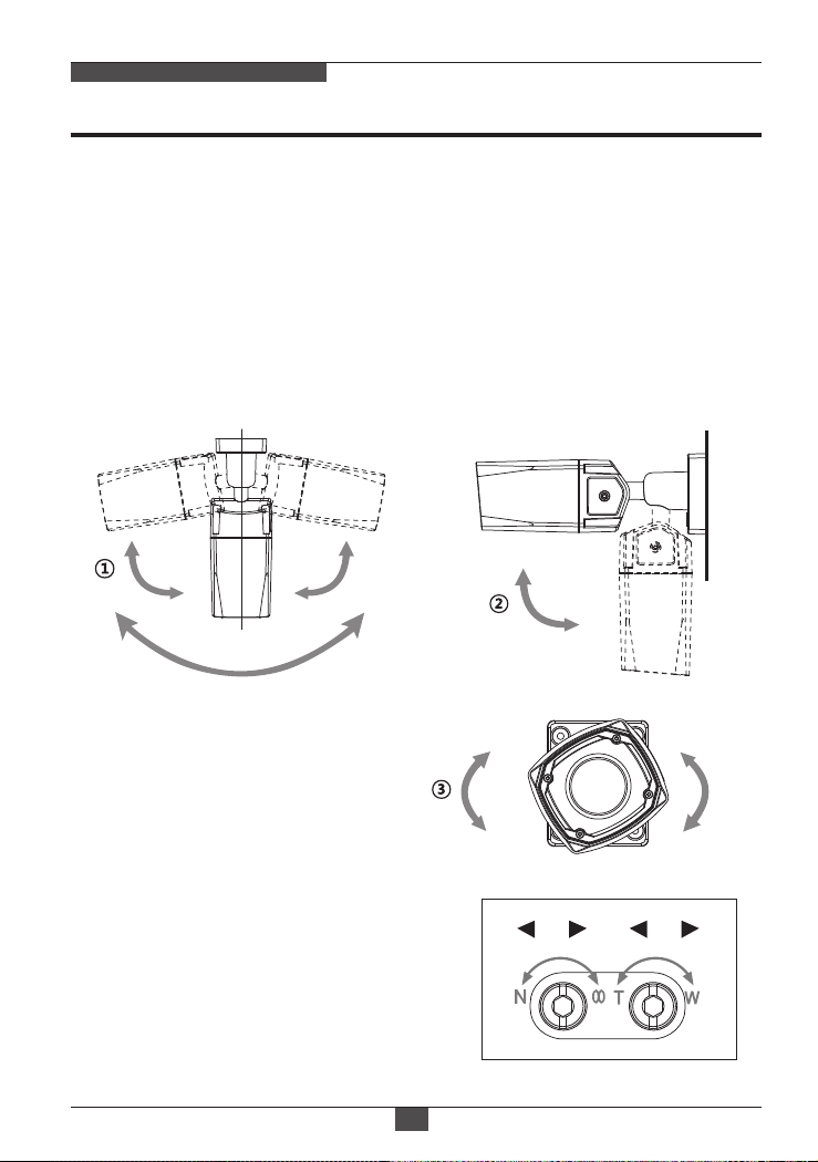
• External Zoom & Focus adjustment
• Built-in 4pcs High power SMD LED
• LED ON/OFF Control
• Up the Coaxial (UTC) communication
• RS-485 control
• OSD Menu & Video Sub-out port for easy installation & maintenance
• Circuit protection against faulty connection in power polarity
• Isolated power supply against ground loop problem
• One touch 3-Axis bracket, easy installation pad
• Dual Window
• IP67 protection
• With ICR mechanism,
- Enhances its sensitivity about 10x at night time
- Can accepts the infrared light
This is an ultra-clear resolution camera which realizes over 750TVL resolution
and a crisp color reproduction with SONY 960H CCD and Effio-V Enhanced
image signal processor.
• With Effio-V series Enhanced digital imaging system,
- Delivers the crystal clear images providing 750TVL resolution in conjunction
with SONY 960H High density CCD.
- They are provided ‘TRUE WDR’ function
- Color signal processing provides the optimum balance between the luminance
and chroma signals for high color reproducibility even for the detail scene which
contains very high spatial frequency.
- Incorporates 2D+3DNR signal processing.

ULTRA CLEAR RESOLUTION CAMERA
Composition
07
Dimensions
(unit : mm)
Operating
Instruction
Camera
61
76
69
75.3
218.5
145.8
Mounting
Template
Torque Wrench:
3mm (1pc)
Assembly Screw:
4 x 13mm (4pcs)
Mounting Screw:
4 x 35mm (4pcs)
Plastic Anchor:
6 x 30mm (4pcs)
Easy
Bracket
Video Sub-out
Cable (1pc)
Cable Signal
Sticker
Wiring Connector:
(1pc)

ULTRA CLEAR RESOLUTION CAMERA
Part Names
08
REAR
VIEW
FOCUS ZOOM
DUAL WINDOW
POWER CABLE
FRONT CASE
EASY
BRACKET
OSD Setup
CONTROL COVER
BRACKET
REAR CASE
• Extreme care should be taken NOT to scratch the window in front of lens.
• Care should be taken the cable is NOT to be damaged, kinked or exposed
in the hazardous area.
• Do not expose the camera directly to a strong light source such as the sun or
spot light.
CAUTION

ULTRA CLEAR RESOLUTION CAMERA
Installation Instructions
09
1. Locate the mounting template at the installation position and drill the ceiling or
wall if needed. ( *The easy bracket can not be installed on the ceiling)
2. Place the easy bracket on pre-drilled position and fix it through using mounting
screws (4x35mm). Skip this step when an easy bracket is not installed.
3. Route the Power cable to the connecting place.
Hook up the camera bracket with the easy bracket as illustrated below.
4. Fix the camera bracket through using assembly screws (4x13mm).
5. Set the camera’s viewing angle and adjust zoom/focus of lens by using the torque
wrench.
Torque Wrench
Assembly Screw
: 4x13mm
Mounting Screw
: 4x35mm
1
2
4
REAR VIEW
3
Cable exit
■Adjustment of viewing angle
with a bracket
Torque
wrench
Lock/Unlock
Screw

ULTRA CLEAR RESOLUTION CAMERA
Installation Instructions
10
Pan & Tilt adjustments
Zoom & Focus adjustments
1) Pan limit:
Pan is limited to +/- 80°.
3) Inclination limit
(Horizontal image alignment):
Inclination limited to +/-90° max.
2) Tilt limit:
Tilt is limited to 0° min ~ 90° max.
for wall(ceiling) installation respectively with
reference to the wall(ceiling) when the
inclination of camera module is 0°, that is,
the image is aligned horizontally.
80° 80°
160°
• Turn the Focus gear to “N”(Near) or “∞”(Far)
until the sharpest focus is made.
• To widen the viewing angle, turn the Zoom to
“W”(Wide) and to obtain a closer view, turn it
to “T”(Tele)
Use the torque wrench supplied.
• Unlock the screw on the camera bracket through using the torque wrench supplied
• Set the camera’s viewing angle then lock the screw on the bracket.
90°
±90°
F Z

ULTRA CLEAR RESOLUTION CAMERA
Installation and commissioning Instructions
• Make sure the power is removed before the installation.
• Follow the order for applying power.
First, connect the low voltage (AC24V or DC12V), then plug the AC adapter to
AC outlets to avoid an improper reset from power jitter and a damage from the
surge voltage when no load.
Power Supply Connections
Camera can work with either 24VAC or 12VDC, dual voltage power.
Primary and secondary grounds are completely isolated to avoid the possible
ground-loop problems
Installation Instructions
11
VIDEO (BNC)
AC24V/GND
AC24V/DC12V
RTX-/RS485
RTX+/RS485
※ Attach the Signal Assignment Sticker
in a visible spot for wiring reference.

ULTRA CLEAR RESOLUTION CAMERA
Operating Instructions
12
Cover Open
Using OSD controller
Setup menu can be accessed and controlled by OSD control joy stick on the
side of camera unit.
Five commands are available with the joy stick.
The design of OSD could be different according to the Model.
Description of the joystick operation
1) SET Key (M) : Access to the menu or enter the setting.
To enter the main menu, press the Set Key down.
2) UP/DOWN Key (U/D) : Choose the desired sub-menu and to move
the cursor up or down.
3) LEFT/RIGHT Key (L/R) : Set up the value of the selected menu. Used
to adjust the desired menu selection and to move the cursor left or right.
OSD Control
Joy Stick
Video Sub-out Connector

ULTRA CLEAR RESOLUTION CAMERA
Operating Instructions
13
OSD menu Startup
OSD menu Table
SETUP MENU
ADVANCED MENU
CONFIGURATION
SCENE SELECT FULL AUTO/ INDOOR/ OUTDOOR/ BACKLIGHT/ ITS/ CUSTOM
SHUTTER/AGC 095
36 DB
OFF
1/50(1/60)
44.8 DB
1/50(1/60)
6.0 DB
230
020
200
INDOOR
010
AE LEVEL
AUTO
AGC MAX
AGC MAX
SENS UP
MANUAL
FIX
ATW
OFF
HLC
WHITE BAL
HLC / BLC
SHUTTER
AGC MAX
SHUTTER
SPEED
DELAY CNT
ATW FRAME
ENVIRONMENT
CLIP LEVEL
• / : Selects previous page or next page.
• EXIT : Enters ‘EXIT’ menu.
• RETURN : Returns to the previous menu.
Press the ‘OSD menu SET key’ down to access the setup menu mode.
SETUP MENU
1 / 2
SCENE SELECT
PICT ADJUST
EZOOM
DIS
PRIVACY MASK
MOTION DET
SYS SETTING
OFF
OFF
OFF
EXIT
FULL AUTO
SETUP MENU
2 / 2
LANGUAGE
VERSION
MAINTENANCE
EXIT
ENGLISH
1.03

ULTRA CLEAR RESOLUTION CAMERA
Operating Instructions
14
OFF
EXT1
005
078
120
AUTO
---
02
OFF / ON
OFF / ON
DAY/NIGHT
/ OFF/ FIX
SET1/2/3
480
290
MID
PICT ADJUST
EZOOM
DIS
IR OPTIMIZER
LENS SHD COMP
DEFOG
FLK LESS
ANTI CR
BRIGHTNESS
CONTRAST
SHARPNESS
HUE
COLOR GAIN
OFF (default)
ON
OFF (default) / ON
AREA SEL
DISPLAY
110
30
08
064
128
MAG
PAN
TILT
1/15
OFF
000
512
256
WDR / ATR-EX
DNR
DAY/NIGHT
3
BURST
CNTL SIGNAL
DELAY CNT
DAY->NIGHT
NIGHT->DAY
MODE
IR AREA
LEVEL
IR LED
COLOR NIGHT
IR SHADE COMP
PATTERN
POSH
POSV
LEVEL
BURST OFF
SHUTTER FIX
SHUTTER FIX
MODE
MODE
ON
DAY
NIGHT
OFF (default)
OFF
ON
OFF
ON
OFF
AUTO (default)
ON
AUTO / OFF / ON
SCENE SELECT
PRIVACY MASK
LEVEL
AUTO
WDR for V-Series, ATR-EX for A-Series

POSITION
COLOR
ULTRA CLEAR RESOLUTION CAMERA
Operating Instructions
15
PRIVACY MASK
MOTION DET
SYS SETTING
LANGUAGE
VERSION
MAINTENANCE
EXIT
TRANSP
MOSAIC
111
001
OFF
AREA SEL
AREA MODE
TOP
BOTTOM
LEFT
RIGHT
TYPE
MODE
ADJUST
SPEED
PELCO-D
001
9600
8
OFF
1
OFF (default)
ON
LENS
COMMUNICATION*
(Option)
CAMERA ID
1.03
W.PIX MASK
CAMERA RESET
SAVE / NOT SAVE / CANCEL / BACK
DETECT SENSE
INTERVAL
BLOCK DISP
MASK AREA
MONITOR AREA
AUTO
FLIP
LCD / CRT
PROTOCOL
ADDRESS
BAUDRATE
DATABIT
PARITY
STOPBIT
OFF / ON
MANUAL
AUTO
DATA CLEAR
LEVEL1 / LEVEL2 / AUTO
YES / NO
1/4
OFF
03
04
04
08
DC
AUTO
030
REGISTRATION
REG. POINT
CURSOR COLOR
BLINK
REG. NUMBER
OFF / V / H / HV
CRT
English/ Spanish/ Russian/ Portuguese/ German/ French/ Chinese/ Japanese

ULTRA CLEAR RESOLUTION CAMERA
Operating Instructions
16
OSD menu Setup
Press the OSD menu SET key down to access the setup menu mode.
Sets the SHUTTER/AGC level to AUTO, MANUAL or FIX.
These options have been pre-configured at the factory for optimal performance.
You can choose one of FULL AUTO, INDOOR, OUTDOOR, BACKLIGHT, ITS
and CUSTOM according to the environments.
Each SCENE preset offers how to set SHUTTER +AGC, WHITE BAL, HLC/BLC,
WDR/ATR-EX, DNR, DAY/NIGHT, IR OPTIMIZER, LENS SHD COMP, DEFOG,
FLK LESS, and ANTI CR functions to get the best image for the SCENE SELECT.
If the selected preset does not seem to be the best choice, the further adjustments
are available in each preset.
1. SCENE SELECT
1-1. SHUTTER/AGC
Video level is automatically controlled to follow the settings of AE LEVEL, AGC
MAX, SENS UP. In this mode, ‘DC Auto Iris Lens’ and ‘Fixed Lens’ are available.
1-1-1. AUTO:
> FULL AUTO: Optimized for the general scene.
> INDOOR: Optimized of indoor environment.
> OUTDOOR: Optimized of outdoor environment.
> BACKLIGHT: Optimized for backlight condition such as near the window in
daylight.
> ITS: Optimized for the environment on traffic roads.
> CUSTOM: Setting for user customized environment.
SETUP MENU
1 / 2
SCENE SELECT
PICT ADJUST
EZOOM
DIS
PRIVACY MASK
MOTION DET
SYS SETTING
OFF
OFF
OFF
EXIT
FULL AUTO
ADVANCED MENU
1 / 2
SHUTTER/AGC
WHITE BAL
HLC/BLC
WDR/ATR-EX
DNR
DAY/NIGHT
IR OPTIMIZER
RETURN
AUTO
ATW
OFF
WDR
NIGHT
ON

ULTRA CLEAR RESOLUTION CAMERA
Operating Instructions
17
Video level is manually controlled by the settings of SHUTTER, AGC MAX.
In this mode, ‘DC Auto Iris Lens’ is only available.
1-1-2. MANUAL:
Automatically tracks the changes of color temperature and continuously
adjusts the white balance. The white balance range is 1,800°K~10,500°K.
Note: If you set to ‘CUSTOM’ mode in ‘SCENE SELECT’ menu, the ‘WHITE BAL’
sub-menu will be appeared ‘ATW/ PUSH/ USER1/ USER2/ MANUAL/
PUSH LOCK’ functions that you can select one.
Other modes in ‘SCENE SELECT’ menu, the ‘WHITE BAL’ sub-menu is
only ‘ATW’ function.
Can set the WHITE BALANCE mode.
1-2. WHITE BAL
ATW
SPEED
DELAY CNT
ATW FRAME
ENVIRONMENT
230
RETURN
INDOOR
020
200
1-2-1. ATW (Auto Trace White Balance):
Video level is fixed in any conditions by the setting of SHUTTER, AGC MAX.
1-1-3. FIX:
Adjusts the AWB compensation delay to next update of AWB.
The smaller value will update AWB more frequently (faster).
• DELAY CNT (default: 020):
Determines the ATW range with respect to the fundamental range. Higher value
extends the ATW range at lower and higher color temperature.
• ATW FRAME (default: 200):
• SPEED (default: 230):
Sets the AWB(Automatic White Balance) compensating speed. Lower value makes
AWB faster. * Too fast AWB may make the color oscillation.

ULTRA CLEAR RESOLUTION CAMERA
Operating Instructions
18
Selects INDOOR, SUNNY, SHADE or AUTO
Their ATW is optimized for the limited application and can not cover
• ENVIRONMENT (default: INDOOR):
1-3. HLC/BLC
> INDOOR : Optimized for Indoor installation and more easily compensates ATW
for low color temperature such as incandescent lights.
>SUNNY : Optimized for outdoor sunlight applications and more easily compensates
ATW for high color temperature such as sunlight.
> SHADE : Optimized for shade area compensation.
>AUTO : Optimized for general scene.
Disables HLC and BLC functions.
1-3-1. OFF:
HLC (Highlight Cut out) :
This function is used to black out highlighted areas, in order to enable a clear visual
image of objects, such as the license plates of an oncoming vehicle or other objects
that may be obstructed by headlamps.
HLC OFF HLC ON
BLC OFF BLC ON
BLC (Backlight Compensation) :
This function is used to brighten an image in the foreground with a highly light area
behind it such as sunlight, limiting the affect of silhouette.

ULTRA CLEAR RESOLUTION CAMERA
Operating Instructions
19
Sets enabling/disabling ATR compensation for the better dynamic range
(D-WDR) of the image.
ATR feature improves the dynamic range and the visibility of the image by
providing the optimal gradation compensation of the image in one field. This is
achieved by two ways of image processing, luminance compression and contrast
enhancement, so that the tone can be enhanced at highlight and dark area.
Defines the threshold level for HLC. Lower value masks more.
• CLIP LEVEL (default: 010):
HLC clips out the highlight area and masks it as black color.
Video will be clipped out and masked for the area which exceeds CLIP LEVEL.
1-3-2. HLC:
1-4-1. WDR(Wide Dynamic Range): V-Sereis Only
1-4-2. ATR-EX (Adaptive Tone Reproduction-EX):
• CONTRAST (default: MID): It can be selected only in ‘CUSTOM’ scene preset.
• CLEAR FACE (default: MID): Selects one of ‘LOW/MID/HIGH’
1-4. WDR/ATR-EX
This function is extended the gain range of the screen that is mostly useful if
camera takes a simultaneous picture of both indoor and outdoor nearby window.
It improves contrast of the picture in outdoor scenery as well as indoor.
Video outputs image processed from two images by dual shutter (long and short
shutter) in a field to provide the best dynamic range. Highlight area is compensated
by the short shutter and dark area is compensated by the long shutter.
Final video may have less contrast compared to the conventional camera which
does not have WDR function.
1-5. DNR
DNR(Digital Noise Reduction) function improves picture quality by filtering out
signal noise which is generated under the low light conditions.
It is 3DNR(3-dimensional noise reduction) which reduces the noise by the multi
frames. Noise Reduction is effective at low light. Setting high level is strength of
noise reduction but the result may occur in loss of sharpness and the tail effect
of a comet.
Sets BLC function enables or disables
1-3-3. BLC:
Note: BLC is available only in ‘CUSTOM’ scene preset.
Note: WDR is fixed except ‘CUSTOM’ scene preset.
Selects one of ‘WDR/ATR-EX/OFF’ is only in ‘CUSTOM’ scene preset.

ULTRA CLEAR RESOLUTION CAMERA
Operating Instructions
20
AUTO mode in DAY/NIGHT is used only for a camera which does not have
a light sensor. Camera switches DAY from/to NIGHT automatically along with
the amount of light through the lens.
DAY/NIGHT is switched by amount of light through the lens.
Selects one of ‘INT/EXT1/EXT2’
• CNTL SIGNAL (default: EXT1):
1-6-1. AUTO
DAY→NIGHT is a threshold level which determines to switch from DAY to
NIGHT. Lower(Higher) value makes the camera switch from Day to Night at
lower(higher) illumination. If it stays in Day(Color) mode at night time, increase
DAY→NIGHT threshold value until it just switches to Night.
* Examine and verify Day/Night operation according to IMPORTANT ACTIVITY
• DAY -> NIGHT (default: 078)
D/N AUTO SETUP
BURST
CNTL SIGNAL
DELAY CNT
DAY->NIGHT
NIGHT->DAY
005
RETURN
OFF
EXT1
078
120
BURST determines whether a color burst signal keeps output or eliminated
when camera switches to B/W.
If set to ON, B/W video signal contains color burst signal and is compatible
with the color equipment but shows the same resolution as color video.
If set OFF, the color burst signal is removed from B/W video and shows better
resolution but rarely the compatibility problem may occur with the color equipment.
• BURST (default: OFF)
DELAY CNT is time in second while camera maintains its status before Day↔
Night switches. DELAY can avoid the unwanted/frivolous switching by a short
term lights such as light from the passing car.
• DELAY CNT (default: 005)
1-6. DAY/NIGHT
This function is used to control the setting during day-time and night-time operation.
Table of contents
Other Eneo Digital Camera manuals

Eneo
Eneo VKC-1369 User manual

Eneo
Eneo HDB-2000MIR720 User manual

Eneo
Eneo IPD-65M2713P5A User manual

Eneo
Eneo VKC-1368-WL/W3 User manual

Eneo
Eneo VKC-1374/IR User manual

Eneo
Eneo VKC-1359BIR/W3P User manual

Eneo
Eneo APB-7SV2812MVA User manual

Eneo
Eneo VKC-1327A/VAR49 User manual

Eneo
Eneo HDC-1004M1080 User manual

Eneo
Eneo ISM-62F0028W0A User manual