2
CAUTION: Avoid damaging hydraulic hose. Avoid
sharp bends and kinks when routing hydraulic hoses.
Using a bent or kinked hose will cause severe back-
pressure. Sharp bends and kinks will internally damage the
hose leading to premature hose failure.
®
Do not drop heavy objects on hose. A sharp impact
may cause internal damage to hose wire strands.
Applying pressure to a damaged hose may cause it
to rupture.
IMPORTANT: Do not lift hydraulic equipment by the
hoses or swivel couplers. Use the carrying handle or
other means of safe transport.
CAUTION: Keep hydraulic equipment away from
flames and heat. Excessive heat will soften packings
and seals, resulting in fluid leaks. Heat also weakens
hose materials and packings. For optimum performance do not
expose equipment to temperatures of 150°F [65°C] or higher.
Protect hoses and cylinders from weld spatter.
DANGER: Do not handle pressurized hoses. Escaping
oil under pressure can penetrate the skin, causing
serious injury. If oil is injected under the skin, see a
doctor immediately.
WARNING: Only use hydraulic cylinders in a coupled
system. Never use a cylinder with unconnected
couplers. If the cylinder becomes extremely overloaded,
components can fail catastrophically causing severe
personal injury.
®
WARNING: BE SURE SETUP IS STABLE BEFORE
LIFTING LOAD. Cylinders should be placed on a flat
surface that can support the load. Where applicable, use
a cylinder base for added stability. Do not weld or
otherwise modify the cylinder to attach a base or other support.
Avoid situations where loads are not directly centered on the
cylinder plunger. O-center loads produce considerable strain
on cylinders and plungers. In addition, the load may slip or fall,
causing potentially dangerous results.
Distribute the load evenly across the entire saddle
surface. Always use a saddle to protect the plunger.
IMPORTANT: Hydraulic equipment must only be
serviced by a qualified hydraulic technician. For repair
service, contact the Enerpac Authorized Service Center
in your area. To protect your warranty, use only Enerpac oil.
WARNING: Immediately replace worn or damaged
parts with genuine Enerpac parts. Standard grade parts
will break causing personal injury and property damage.
Enerpac parts are designed to fit properly and withstand high
loads.
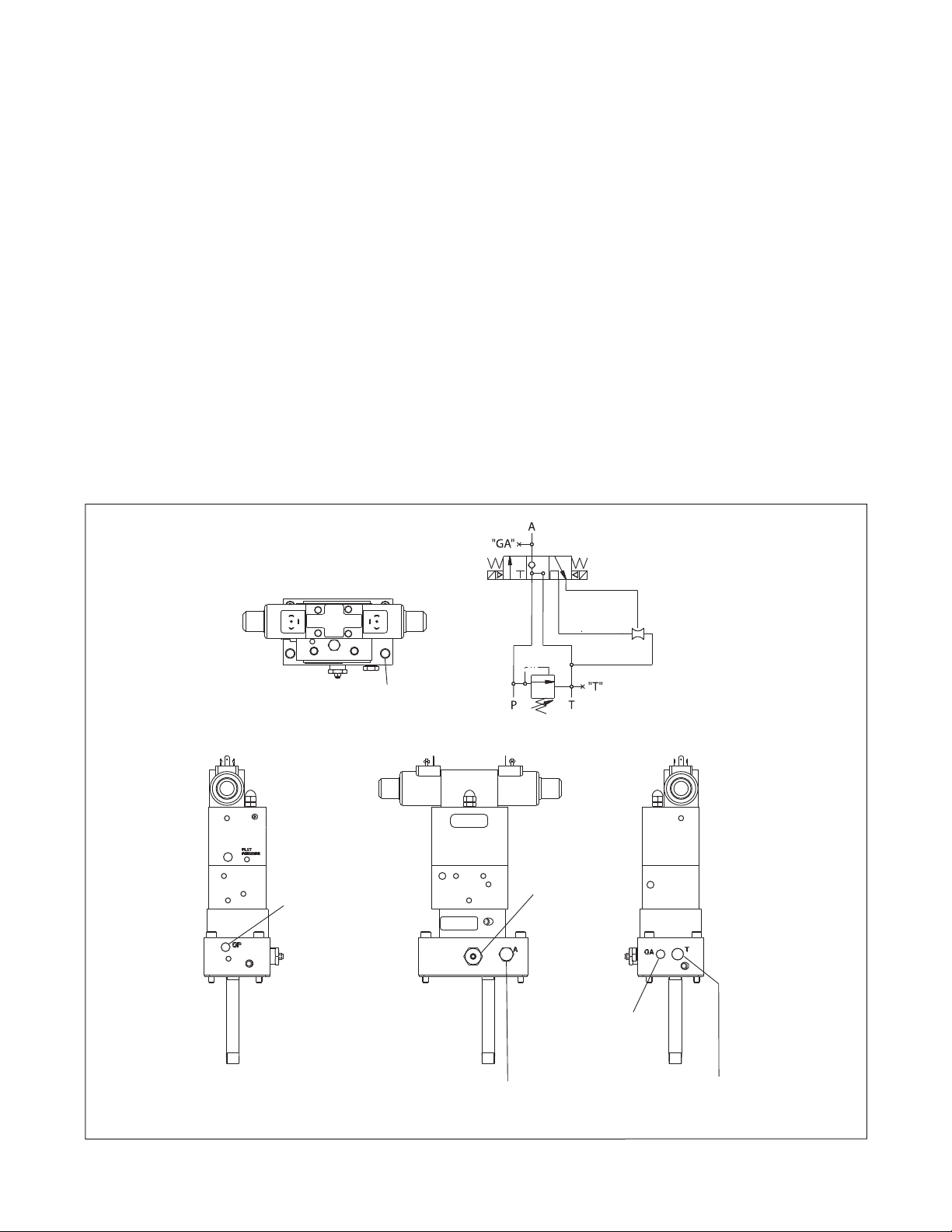
3.0 GENERAL INFORMATION
The Enerpac valve design incorporates the following features
into a single unit:
• 10,000 psi [700 bar] operating pressure
• Vacuum-assisted return (single-acting cylinders only)
• Load holding
• Electrical fail-safe control
• Manual override, (requires pump to run)
• User adjustable relief valve
• Gauge ports
The Enerpac valves are specifically designed for use with Enerpac
electric powered pumps and electric controls.
3.1 Capacity
Capacity is 900 cu. in/min [14.8 l/min], equivalent to
approximately 3.9 gallons per minute.
4.0 INSTALLATION
CAUTION: If you are not trained and familiar with
installing a control valve have an Enerpac Authorized
Service Center perform this procedure.
WARNING: DO NOT USE THESE VALVES WITH A
DOUBLE-ACTING CYLINDER.
1. Install valve onto Enerpac pump using gasket and fasteners
included. Torque fasteners to 16-19 ft-lbs [21.7-25.8 Nm].
Take needed steps to ensure pump’s pressure tube o-ring
and backup are not damaged. Verify tank return tube is
installed to the valve.
2. Connect two (2) solenoid cords from electrical box to
valve.
3. Connect and secure hose and cylinder.
CAUTION: If using pipe sealants on make pipe thread,
use sparingly and never over ends of fittings where it can
be torn loose and get into the hydraulic system.
4. Connect control station.
5. Install pressure gauge, if required, into proper port.
Pressure can be monitored at the “GP” port or the “GA”
port or any combination of these, depending on system
requirements.
6. Connect motor to specified electrical outlet.
7. Start pump motor. The valve is now automatically in the
NEUTRAL/HOLD position.
5.0 OPERATION
1. To advance load, depress the “up” arrow button on control
station.
2. To hold load, remove finger from control stations.
3. To retract load, depress the “down” arrow button on
control stations. (NOTE: The motor must be running.)
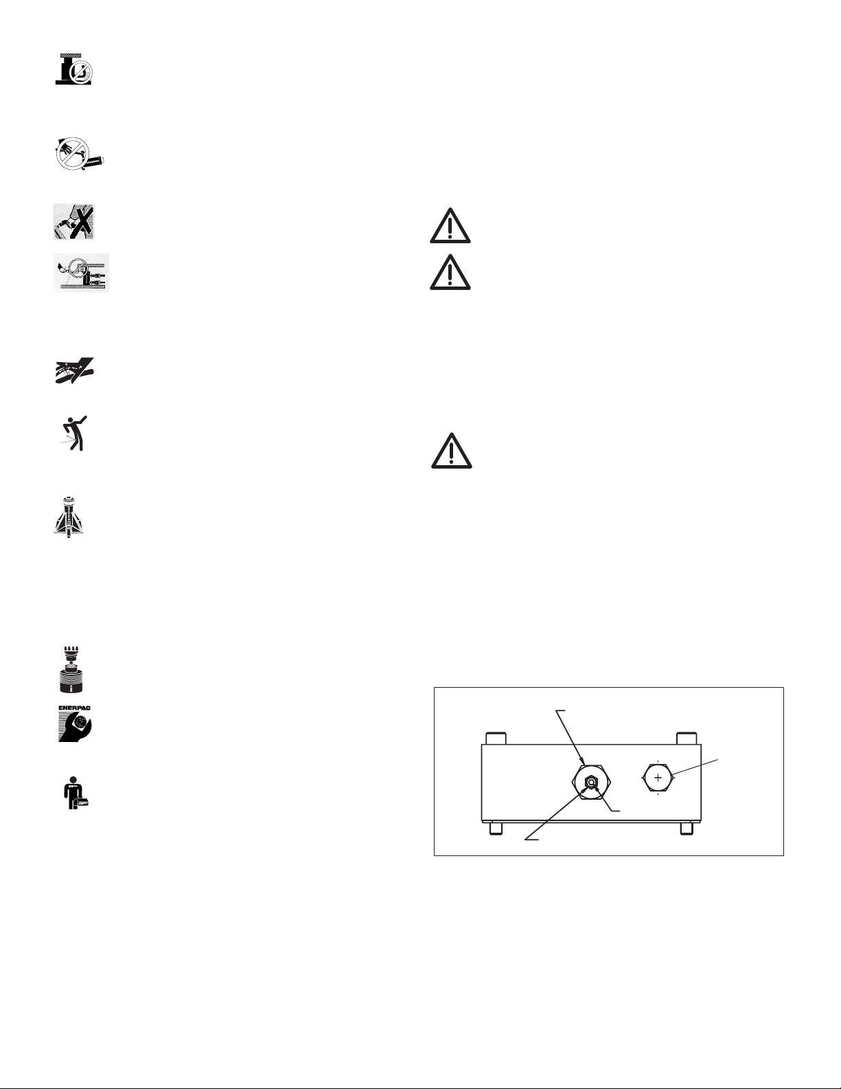
5.1 Relief Valve Adjustment
Z-Class pumps are equipped with one user adjustable relief
valve (see Figure 1). It can be adjusted as follows:
1. Install a gauge on the pump. If the valve is equipped with
Relief valve body
(DO NOT TURN relief valve body.)
Locknut
Set screw
Figure 1, Relief Valve Adjustment
"A" Port