2
CAUTION: Avoid damaging hydraulic
hose. Avoid sharp bends and kinks
when routing hydraulic hoses. Using a
bent or kinked hose will cause severe back-
pressure. Sharp bends and kinks will internally
damage the hose leading to premature hose
failure.
®
Do not drop heavy objects on hose. A
sharp impact may cause internal
damage to hose wire strands. Applying
pressure to a damaged hose may cause it to
rupture.
IMPORTANT: Do not lift hydraulic
equipment by the hoses or swivel
couplers. Use the carrying handle or
other means of safe transport.
CAUTION: Keep hydraulic equipment
away from flames and heat. Excessive
heat will soften packings and seals,
resulting in fluid leaks. Heat also weakens hose
materials and packings. For optimum
performance do not expose equipment to
temperatures of 65°C [150°F] or higher. Protect
hoses and cylinders from weld spatter.
DANGER: Do not handle pressurized
hoses. Escaping oil under pressure
can penetrate the skin, causing
serious injury. If oil is injected under the skin,
see a doctor immediately.
WARNING: Only use hydraulic
cylinders in a coupled system. Never
use a cylinder with unconnected
couplers. If the cylinder becomes extremely
overloaded, components can fail
catastrophically causing severe personal injury.
IMPORTANT: Hydraulic equipment
must only be serviced by a qualified
hydraulic technician. For repair
service, contact the Authorized ENERPAC
Service Center in your area. To protect your
warranty, use only ENERPAC oil.
WARNING: Immediately replace worn
or damaged parts with genuine
ENERPAC parts. Standard grade
parts will break causing personal injury and
property damage. ENERPAC parts are designed
to fit properly and withstand high loads.
4.0 PRV-8 AND PRV-9 PRESSURE
REDUCING VALVES
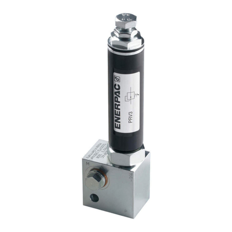
The PRV-8 and PRV-9 remote mount pressure
reducing valves can be used with fittings
and tubing or can be manifold mounted. The
valve section is normally open, and closes
when the cylinder pressure downstream of the
valve reaches the customer adjusted pressure
setting.
When pressure in the incoming side drops
below that of the cylinder side, reverse flow is
allowed, enabling clamped cylinders to unclamp.
Pressure adjustment is through an adjustment
screw. Adjustment is clockwise to increase
the pressure setting and counterclockwise
to reduce the pressure setting. A locknut is
provided to secure the setting.
A 1/8"-27 NPT port on the manifold body allows
the mounting of a gauge to read the cylinder
pressure past the valve section.
Refer to figures 1 and 2 for additional
information.
WARNING: Maximum allowable
system pressure for the PRV-8 and
PRV-9 valves is 350 bar [5000 PSI].
Do not exceed this pressure rating.
5.0 PRVM-2 MANIFOLD
The PRVM-2 manifold is included as part of the
PRV-8 and PRV-9 pressure reducing valves.
If desired, the PRVM-2 manifold may also be
purchased separately.
• Assembling a PRVM-2 manifold and a PRV-3T
valve module will create a PRV-8 pressure
reducing valve.
• Assembling a PRVM-2 manifold and a PRV-4T
valve module will create a PRV-9 pressure
reducing valve.
Refer to figures 3 and 4 for additional
information.
AP
Figure 1, PRV-8 and PRV-9 Valve Function
