manuals.online logo
Brands
  1. Home
  2. •
  3. Brands
  4. •
  5. Epson
  6. •
  7. Fax Machine
  8. •
  9. Epson PriorityFAX 3000 Dimensions

Epson PriorityFAX 3000 Dimensions

EPSON
EPSON AMERICA, INC.
INFORMATION
Product Support Bulletin
Subject: PriorityFax 2000/3000 Maintenance Switch Function Tables
Date: 8/8/90
PSB No: P-0070
Page: 1 of 8 Originator: VB
The purpose of this document is to describe the PriorityFax 2000/3000
maintenance soft switch functions and supply instructions for accessing them.
ACCESSING THE MAINTENANCE MODE
1. In normal operation mode without a document inserted, press
“FUNCTION l2 8 6 4” in the following sequence.
A. Press “FUNCTION” then immediately press “*“.
B. The unit will beep 3 times.
C. Immediately following the 3 beeps, press ’ 2 8 6 4 “.
NOTE: Numbers must be pressed in rapid succession.
2. The unit will emit one long beep and the LCD will display
“MAINTENANCE”, indicating it is in maintenance mode.
If the LCD does not display ‘MAINTENANCE”, press “STOP”, wait for
the LCD to display the date and time, then try step 1 again. Call
Epson Product Support at 213-539-9955 if assistance is required.
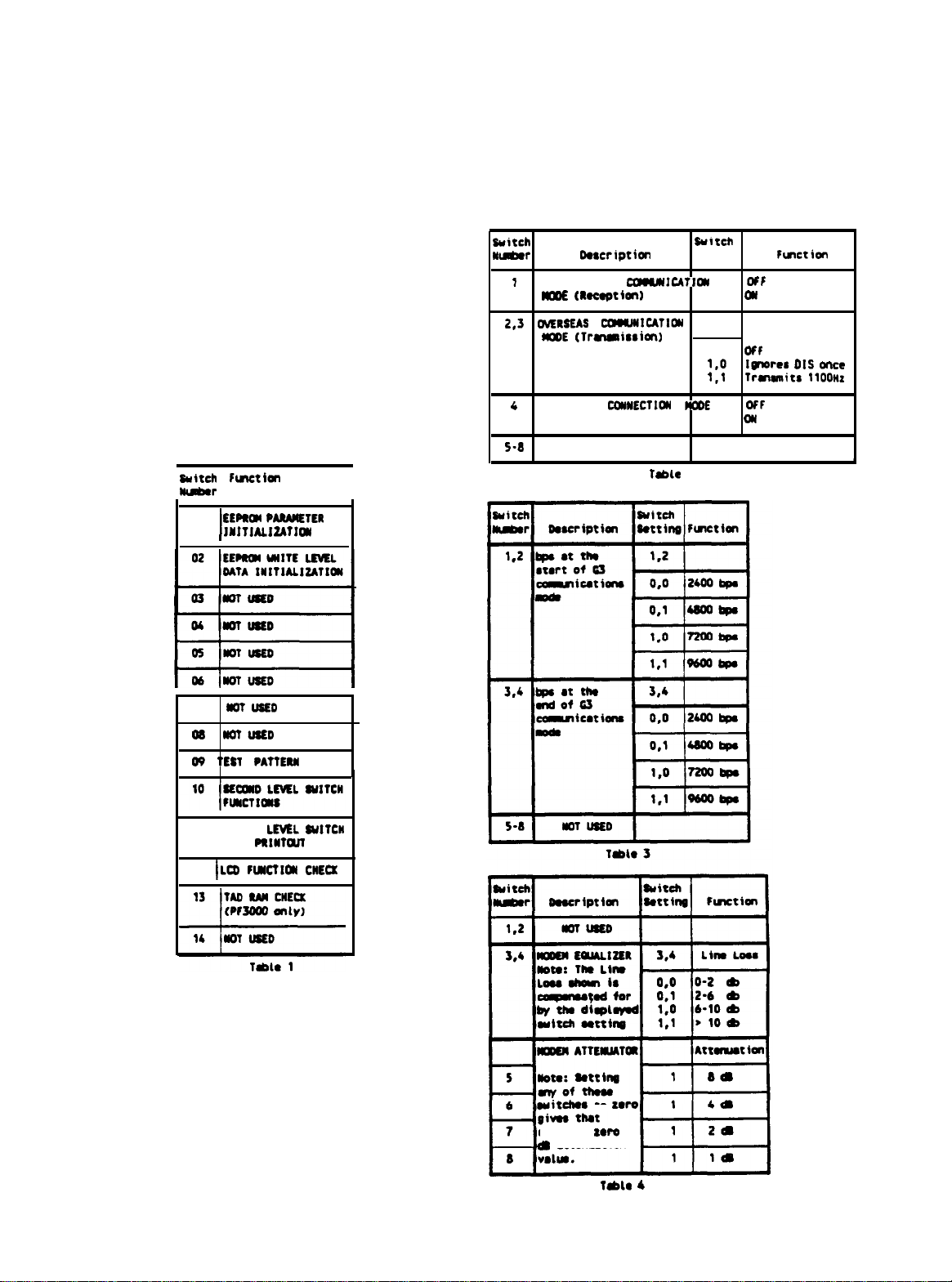
3. There are 2 levels of soft switch functions accessible in the
maintenance mode. Table 1 lists the initial level functions. Tables 2,
3, and 4 list the second level functions. The tables are located at the
end of this document.
4. To activate one of the functions listed in Tab 1, enter the initial
maintenance mode. Enter the two digit ‘Switch Number” with the keys
on the control panel. The unit will perform the function and return to
the initial maintenance mode.
The functions marked ‘NOT USED’ are either not available or require
Specialized equipment. They should only be accessed by an
authorized Epson Customer Care Center.
PSB No: P-0070
Page: 2 of 8
5. Pressing the “STOP” key in the initial maintenance mode returns the
unit to normal operation.
Pressing the “STOP” key when only one digit has been entered returns
the unit to the initial maintenance mode.
The unit returns to the initial maintenance mode when the number
entered does not correspond to a function listed in Table 1.
EEPROM PARAMETER INITIALlZATION
Function
Sets the EEPROM memory content, user switch data, and soft switch data
to the factory default settings.
Operation Method
1. To activate the EEPROM Parameter Initialization, enter the initial
maintenance mode. Press the “0” key one time and then press the “1”
key one time.
The LCD will display “PARAMETER INIT”.
2. Upon completion of the EEPROM Parameter Initialization, the unit Will
emit one long beep indicating it has returned to the initial maintenance
mode.
EEPROM
WHITE LEVEL DATA INITIALIZATION
Function
The unit spans a blank white sheet of paper to establish a white level
reference point that is used for comparison of black
and white
levels.
Operation Method
1.
2.
3.
To activate the EEPROM White Level Data
Initialization,
enter the
initial
maintenance mode. Load a blank white sheet of paper in the
document slot.
Press the “0” key one time and then press the “2” key one time. The
LCD will display “WHITE LEVEL
INIT”.
Upon completion of the EEPROM white Level Data Initialization, the unit
will emit one long beep indicating it has returned to the initial
maintenance mode.
PSB No: P-0070
Page: 3 of 8
EST PATTERN
1. To print the test pattern, enter the initial maintenance mode. Press the
“0” key one time and then press the “9” key one time. The unit will
continue to display “MAINTENANCE” on the LCD and print a test
pattern as shown in Figure 1.
2. Upon completion of printing the test pattern, the unit will emit one long
beep indicating it has returned to the initial maintenance mode.
a
n
-mirmvm
n
I
aa
a
a
a
a
m
n l
m
rn"%rnrnrn,
8
15
‘@
n l
I
%
n n
n n
n
l mmmmmmmmmmmmmmmmmmmmmmmmm
n n n n n n n n n n n n n n n n n n n n n n n n n
mmaammmmmmmmmmmmmmmmmmmmmm
•~lam~mmm~~~~m~m~m~mm~~mmm
,
,I*
SECOND LEVEL SOFT SWITCH FUNCTIONS
1. To
8nt8r
the
Second
b/81
Soft Switch Functions,
8nt8r
the initial
maintenance
mode.
Press the
‘1”
k8y
one time and
then
press the
“0”
key one time. When
the
unit is
set
to the factory default settings, the
LCD will display
%/SW1
=,oooooooo”.
Each
“0”
is
r8ferred
to as a
‘Switch” and they are numbered from
left
to right 1 through 8. Table
2
lists the function of
8aCh
WSWl
switch.
2.
The
cursor, which is the line under the first 0 on the LCD, can be
moved
under any of the 8 characters that
need
to be changed by
using
ttl8
“R”
or
“**
key.
3. To
Change
a function place the cursor under the switch that needs
to
be changed and press either the
“1”
or
“0”
key as necessary.
4.
5.
6.
7.
PSB No: P-0070
Page: 4 of 8
Pressing the “Next” key will store the values of
WSWl
in the EEPROM
and make
“WSW2”
available for change.
When
the unit is set to the
factory default settings, the LCD will display “WSW2=
113DOOOO”.
Table
3 lists the function of
8aCh
WSW2 switch.
In this mode, every time
the
“NEW
key is pressed, the Current switch
settings are finalized and the next switch bank,
WSWl,
WSW2 or
WSW3, in that order, is made available. Table 4 lists the function of
each WSW3 switch.
If
the
“SF
key is pressed, the current switch bank settings are saved.
The unit then emits one long
beep
indicating that it has returned to the
initial maintenance mode.
When
the “STOP” key is
preSSed,
any changes made are canceled.
Th8
Unit
then
emits
one
long
b88p
indicating that it has
r8tUtTI
t0
the
initial
maintenance
mode.
SECOND LEVEL SOFT SWITCH FUNCTION DESCRIPTIONS
Tab18
2 Switch 1: Overseas communication
mod8
(reception)
Setting
switch 1 to a “1” allows the unit to acknowledge the 1100 Hz
signal that suppresses echoes, instead of a 2100
Hz which
disables the
echo suppressor (ES). Suppressing
th8
8Cho8S
provides
a more
reliable
method
of establishing communications.
Table 2 Switches 2 & 3: Overseas communication
mod8
(Transmission)
When
switch 2 is
set
to ‘1” and 3 is
set
to
“O”,
the unit
ignores
the
DIS signal sent from the calling station for suppressing echoes. Note:
Some called
models
may cause an
error by receiving an
echoed
DIS.
When
both switches 2 and 3 are set to
“l”,
the unit
transmits
an 1100
Hz signal for 3
Seconds
upon detection of the DIS V.21
flag.
This
operation
prevents
the called
station
from receiving its own DIS and
enables a no-
canier
state
until
th8
unit transmits a
subsequ8ntial
DIS.
Table 2
Switch 4:
Direct
connection
mod8
When this
8witoh
is
set
to 1,
the
unit
starts
receiving signals
from
the
remat
station
when
th8
“START”
k8y
is pressed,
r8gardl8S8
of whether
the hand
set
is on
-
hook or off
-
hook.
This mode is used for Cross
testing 2
fax
machines when they
are
connected directly to
8aCh
other.
PSB No: P- 0070
Page: 5 of 8
Table 3
-
Switches 1
-
4: Start/End Transmission speed in G3 mode
The starting and ending transmission speed can be set separately in
G3 overseas communication mode. If there is excessive noise,
decrease the starting
Speed.
Increase
the ending
Sp88d
if
th8
transmission of the document
takes
too long. These settings are
independent of the overseas communications mode (Table 2 switches 2
and 3).
Table 4
-
Switches 3 & 4: Modem Equalizer
These switches are
uSed
for setting the Modem
Equalizer
to
compensate for line loss.
m8
function section of Table 4 lists the
relationship between the line loss and the appropriate switch setting
that compensates for that loss.
Table 4
-
Switches
5-
8: Modem Attenuator
These switches are used to adjust the transmission level attenuation.
The amount of attenuation is
accumulative
when setting more than one
switch to “1”.
For example, if switches 5 and 6 are set to
“1”
and
switches 7 and 8 are set to
“O”,
the accumulative attenuation is 12
dB.
m8
maximum attenuation with all the switches set to
“1’
is 15
dB.
When a switch in this section of table 4 is
set
to
‘0”
that switch value
is 0
dB.
SECOND LEVEL SOFT SWITCH DATA PRINTOUT
Operation Method
1. To print the “SYSTEM
CONFIGUBATION
LIST” which contains the
Second
Level
Soft Switch Data,
8nt8r
th8
initial maintenance
mode.
Press the “1” key twice.
Th8
LCD will continue to display
“MAINTENANCE” and the ‘SYSTEM CONFIGURATION LlSP will be
printed.
2. Upon completion of printing the “SYSTEM CONFIGURATION
UST’,
the
unit will emit one long
beep
indicating it has
rstumed
to the initial
maintenance mode.
PSB No: P- 0070
Page: 6 of 8
LCD FUNCTION TEST
Operation method
1. To activate the LCD Function Test, enter the initial maintenance mode.
Set the “Ring Delay” switch to the “4” position.
2. Press the “1” key one time and then press the “2” key one time. The
LCD will display an oblique pattern (see Figure 2).
3. Confirm that the LCD changes from the oblique, to the all black, and
then the all white pattern every time the
“START’
key is pressed.
4. set the “Ring
Delay”
switch to the
“1”
position.
m8
unit will emit one
long
beep indicating it has
returned
to
th8
initial
maintenance
mode.
Figure 2
PSB No: P- 0070
Page: 7 of 8
TAD RAM CHECK
(PF3000
only)
Function
This function checks whether the TAD (Telephone Answering Device) RAM
functions correctly.
Operation Method
1. To activate the TAD RAM CHECK, enter the initial maintenance mode.
Press the
“1”
key one time and then press the
“3”
key one time. The
LCD will display “TAD RAM CHECK”.
2. Upon completion of the test, the unit will emit one long beep indicating
it has returned to the initial maintenance mode.
3. If an error is detected during the TAD RAM check, the unit will emit a
beep and the LCD will display “TAD RAM ERROR”.
4. Press the “STOP” key while the LCD is displaying
‘TAD
RAM ERROR”,
the unit will emit one long
beep
indicating it has
returned
to the initial
maintenance mode.
PSB No: P- 0070
Page: 8 of 8
Switch
tuution
I I
bkmhr
Description
I
01
I
EEPROl
PARMETER
IYfTlALI2ATIOY
07
lloTusED
I
NOTUSED
09
TEST
PATTERR
11
I
SECOND
LEVEL
RUITCN
DATA
PRIYTM
12
~LtXl
ClWTIOU
CIIEO:
Suitch tu’tch
Y-r
Ooscriptim
Setting
faction
I
OVERSEAS
CC+WRIUTI#
0
OFT
NODE
mceptian)
1
al
2,3
WERSEAS
cmkNI1cATIoy 2.3
MDDE
(lrmmission)
0.0
Mf
l,O
Imores
DIS
once
l,l
lrmsmitr
1100nr
4
DIRECT
CDMWECTIDR
WK)E
0
DFF
1
DR
S-8
NOT USED
T&k
2
witches
to
zwo
witch l
xoro
e
l ttels8stiorl
Idlo
4

Other manuals for PriorityFAX 3000

2

Other Epson Fax Machine manuals

Epson Aculaser CX16NF User manual

Epson

Epson Aculaser CX16NF User manual

Epson PriorityFAX 2000 User manual

Epson

Epson PriorityFAX 2000 User manual

Epson AcuLaser CX37DNF  Guide User manual

Epson

Epson AcuLaser CX37DNF Guide User manual

Epson PriorityFAX 3000 User manual

Epson

Epson PriorityFAX 3000 User manual

Epson PriorityFAX 3000 User manual

Epson

Epson PriorityFAX 3000 User manual

Epson PriorityFAX 2000 User manual

Epson

Epson PriorityFAX 2000 User manual

Epson FX-BO User manual

Epson

Epson FX-BO User manual

Epson PriorityFax 1000 Dimensions

Epson

Epson PriorityFax 1000 Dimensions

Epson X-PRF 1000 User manual

Epson

Epson X-PRF 1000 User manual

Epson PriorityFax 1000 User manual

Epson

Epson PriorityFax 1000 User manual

Epson Stylus CX9400 Instruction Manual

Epson

Epson Stylus CX9400 Instruction Manual

Popular Fax Machine manuals by other brands

Panasonic KX-FB421 operating instructions

Panasonic

Panasonic KX-FB421 operating instructions

Panasonic KX-FPG376 operating instructions

Panasonic

Panasonic KX-FPG376 operating instructions

Brother FAX-1460 Quick setup guide

Brother

Brother FAX-1460 Quick setup guide

HP MFP Analog Fax Accessory 300 Fax guide

HP

HP MFP Analog Fax Accessory 300 Fax guide

Panasonic KX-F1110NZ operating instructions

Panasonic

Panasonic KX-F1110NZ operating instructions

Brother IntelliFax-3550 Service manual

Brother

Brother IntelliFax-3550 Service manual

Olivetti d-Copia 4200MF manual

Olivetti

Olivetti d-Copia 4200MF manual

Minolta MINOLTAFAX 1600 Operator's manual

Minolta

Minolta MINOLTAFAX 1600 Operator's manual

Canon LASER CLASS 3170 user guide

Canon

Canon LASER CLASS 3170 user guide

Philips LaserMFD LFF 6050 Specifications

Philips

Philips LaserMFD LFF 6050 Specifications

Sharp UX-40 Operation manual

Sharp

Sharp UX-40 Operation manual

Minolta 5500 operating instructions

Minolta

Minolta 5500 operating instructions

BT CALLER DISPLAY 2000 user guide

BT

BT CALLER DISPLAY 2000 user guide

Panasonic KX-FT901CX-B Service manual

Panasonic

Panasonic KX-FT901CX-B Service manual

Brother MFC 640CW - Color Inkjet - All-in-One user guide

Brother

Brother MFC 640CW - Color Inkjet - All-in-One user guide

Samsung SF-3200 user guide

Samsung

Samsung SF-3200 user guide

Brother MFC 640CW - Color Inkjet - All-in-One user guide

Brother

Brother MFC 640CW - Color Inkjet - All-in-One user guide

Panasonic KXF1000 - FAX Service manual

Panasonic

Panasonic KXF1000 - FAX Service manual

manuals.online logo
manuals.online logoBrands
  • About & Mission
  • Contact us
  • Privacy Policy
  • Terms and Conditions

Copyright 2025 Manuals.Online. All Rights Reserved.