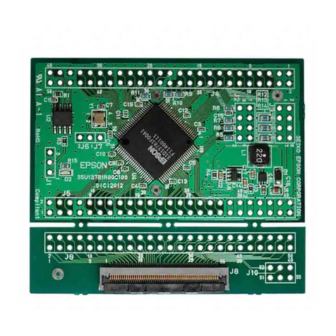
S5U13A05B00C Rev 1.0 Evaluation Board Seiko Epson Corporation 3
Rev. 1.1
Table of Contents
1 Introduction . . . . . . . . . . . . . . . . . . . . . . . . . . . . . . . . . . . . . . . . 5
2 Features . . . . . . . . . . . . . . . . . . . . . . . . . . . . . . . . . . . . . . . . . . 6
3 Installation and Configuration . . . . . . . . . . . . . . . . . . . . . . . . . . . . . . 7
3.1 Configuration DIP Switches . . . . . . . . . . . . . . . . . . . . . . . . . . 7
3.2 Configuration Jumpers . . . . . . . . . . . . . . . . . . . . . . . . . . . . 9
4 CPU Interface . . . . . . . . . . . . . . . . . . . . . . . . . . . . . . . . . . . . . . 13
4.1 CPU Interface Pin Mapping . . . . . . . . . . . . . . . . . . . . . . . . . 13
4.2 CPU Bus Connector Pin Mapping . . . . . . . . . . . . . . . . . . . . . . 14
5 LCD Interface Pin Mapping . . . . . . . . . . . . . . . . . . . . . . . . . . . . . . 16
6 Technical Description . . . . . . . . . . . . . . . . . . . . . . . . . . . . . . . . . 18
6.1 PCI Bus Support . . . . . . . . . . . . . . . . . . . . . . . . . . . . . 18
6.2 Direct Host Bus Interface Support . . . . . . . . . . . . . . . . . . . . . . 18
6.3 S1D13A05 Embedded Memory . . . . . . . . . . . . . . . . . . . . . . . 18
6.4 Adjustable LCD Panel Negative Power Supply . . . . . . . . . . . . . . . . . 18
6.5 Adjustable LCD Panel Positive Power Supply . . . . . . . . . . . . . . . . . . 19
6.6 Software Adjustable LCD Backlight Intensity Support Using PWM . . . . . . . . . 19
6.7 LCD Panel Support . . . . . . . . . . . . . . . . . . . . . . . . . . . . 19
6.7.1 LCD Connector . . . . . . . . . . . . . . . . . . . . . . . . . . . . . . . . . . . . 19
6.7.2 Extended LCD Connector . . . . . . . . . . . . . . . . . . . . . . . . . . . . . . . 20
6.7.3 TFT Type 3 Extended LCD Connector . . . . . . . . . . . . . . . . . . . . . . . . 20
6.8 USB Support . . . . . . . . . . . . . . . . . . . . . . . . . . . . . . . 20
6.8.1 USB IRQ Support . . . . . . . . . . . . . . . . . . . . . . . . . . . . . . . . . . . 20
6.9 External oscillator support for CLKI and CLKI2 . . . . . . . . . . . . . . . . . 20
6.10 External oscillator support for USBCLK . . . . . . . . . . . . . . . . . . . . 20
7 Clock Synthesizer and Clock Options . . . . . . . . . . . . . . . . . . . . . . . . 22
7.1 Clock Programming . . . . . . . . . . . . . . . . . . . . . . . . . . . . 22
8 Parts List . . . . . . . . . . . . . . . . . . . . . . . . . . . . . . . . . . . . . . . . 23
9 Schematics . . . . . . . . . . . . . . . . . . . . . . . . . . . . . . . . . . . . . . . 26
10 Board Layout . . . . . . . . . . . . . . . . . . . . . . . . . . . . . . . . . . . . . . 32
11 Change Record . . . . . . . . . . . . . . . . . . . . . . . . . . . . . . . . . . . . . 34
12 Sales and Technical Support . . . . . . . . . . . . . . . . . . . . . . . . . . . . . 35
