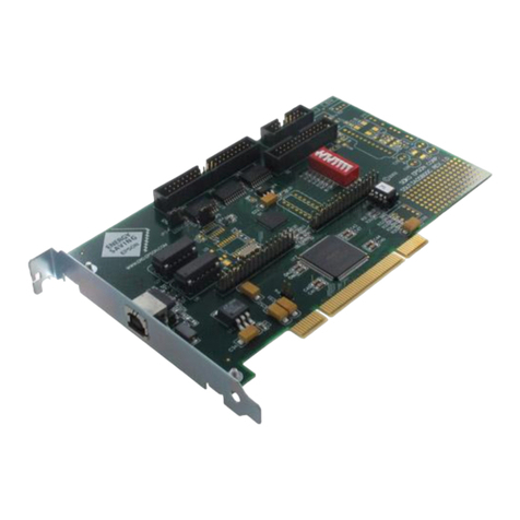
Epson S5U13T04P00C100 User manual

SEIKO EPSON CORPORATION
Rev. 1.0
S5U13T04P00C100
Evaluation Board User Manual
Document Number: XA3A-G-001-00

Page 2
S5U13T04P00C100 Evaluation Board User Manual XA3A-G-001-00
Revision 1.0 Issue Date: 2013/03/15
Seiko Epson Corporation
Evaluation board/kit and Development tool important notice
1. This evaluation board/kit or development tool is designed for use for engineering evaluation,
demonstration, or development purposes only. Do not use it for other purpose. It is not intended to
meet the requirement of design for finished product.
2. This evaluation board/kit or development tool is intended for use by an electronics engineer, and it is
not a consumer product. The user should use these goods properly and safely. Seiko Epson dose not
assume any responsibility and liability of any kind of damage and/or fire caused by usage of it. The
user should cease to use it when any abnormal issue occurs, even during proper and safe use.
3. The parts used for this evaluation board/kit or development tool may change without notice.
NOTICE
No part of this material may be reproduced or duplicated in any form or by any means without the written permission of Seiko
Epson. Seiko Epson reserves the right to make changes to this material without notice. Seiko Epson does not assume any
liability of any kind arising out of any inaccuracies contained in this material or due to its application or use in any product or
circuit and, further, there is no representation that this material is applicable to products requiring high level reliability, such as,
medical products. Moreover, no license to any intellectual property rights is granted by implication or otherwise, and there is no
representation or warranty that anything made in accordance with this material will be free from any patent or copyright
infringement of a third party. This material or portions thereof may contain technology or the subject relating to strategic
products under the control of the Foreign Exchange and Foreign Trade Law of Japan and may require an export license from the
Ministry of Economy, Trade and Industry or other approval from another government agency.
All brands or product names mentioned herein are trademarks and/or registered trademarks of their respective companies.
©SEIKO EPSON CORPORATION 2013, All rights reserved.

Page 3
XA3A-G-001-00 S5U13T04P00C100 Evaluation Board User Manual
Issue Date: 2013/03/15 Revision 1.0
Seiko Epson Corporation
Table of Contents
1
Introduction......................................................................................................................... 4
2
Features ............................................................................................................................. 5
3
Setup and Configuration ..................................................................................................... 6
4
Connectors ......................................................................................................................... 7
4.1 J1 Panel Interface Connector ...................................................................................................8
4.2 J2 Power Connector.................................................................................................................8
4.3 J3 Host Interface Connector.....................................................................................................9
4.4 J4 Production Test Connector ..................................................................................................9
5
Parts List............................................................................................................................10
6
Schematic Diagram............................................................................................................11
7
References ........................................................................................................................13
8
Change Record..................................................................................................................14

Page 4
S5U13T04P00C100 Evaluation Board User Manual XA3A-G-001-00
Revision 1.0 Issue Date: 2013/03/15
Seiko Epson Corporation
1 Introduction
This manual describes the setup and operation of the S5U13T04P00C100 reference board.
This reference board is designed as an evaluation platform for the S1D13T04 EPD Timing Controller.
The S5U13T04P00C100 reference board has a host interface connector, EPD panel connector, and a 2.0
inch EPD panel.
This user manual is updated as appropriate. Please check the Seiko Epson Website at
http://www.epson.jp/device/semicon_e/product/lcd_controllers/index.htm for the latest revision of this
document before beginning any development.
We appreciate your comments on our documentation. Please contact us via email at
documentation@erd.epson.com.

Page 5
XA3A-G-001-00 S5U13T04P00C100 Evaluation Board User Manual
Issue Date: 2013/03/15 Revision 1.0
Seiko Epson Corporation
2 Features
The S5U13T04P00C100 reference board includes the following features:
•Supports SPI host interface
•Epson’s S1D13T04 EPD Timing Controller.
•Power connector
•Panel Interface connector.
•2.0 inch EPD panel.

Page 6
S5U13T04P00C100 Evaluation Board User Manual XA3A-G-001-00
Revision 1.0 Issue Date: 2013/03/15
Seiko Epson Corporation
3 Setup and Configuration
The main functional blocks of the evaluation board are shown below.
Figure 3-1 S5U13T04P00C100 Reference Board Block Diagram
CNF0 is configured with jumpers JP3 and JP4 as shown in the following table.
Table 3-1 CNF0 Configuration Selection
CNF0
JP3
JP4
Comments
0 Open
Short
H_RDY signal is all ways driven (Default)
1 Short
Open
H_RDY signal is open drain signal
S1D13T0
4
J3
Host
I/F
U1
Reserved
For Testing
J4
Panel
I/F
J1
2.
0
Inc
EPD
Panel
Power
J2
JP2
HVDD
Q1
JP
1
RVDD
CNF0
JP3/JP4
SVT13T0
4
board

Page 7
XA3A-G-001-00 S5U13T04P00C100 Evaluation Board User Manual
Issue Date: 2013/03/15 Revision 1.0
Seiko Epson Corporation
4 Connectors
The S5U13T04P00C100 reference board has four connectors for Host Interface, Panel Interface, Power
and Reserved for Production Test (J1, J2, J3 and J4). The location of these connectors is shown in the
following figure.
Figure 4-1 S5U13T04P00C100 Reference Board Top View / Connector Locations
Figure 4-2 S5U13T04P00C100 Reference Board Bottom View
J2 J3
J4
J1

Page 8
S5U13T04P00C100 Evaluation Board User Manual XA3A-G-001-00
Revision 1.0 Issue Date: 2013/03/15
Seiko Epson Corporation
4.1 J1 Panel Interface Connector
The panel interface pins of the S1D13T04 are connected through J2.
Table 4-1 J1 Panel Interface Connector
Connector : J1
Manufacture
: HIROSE FH12S-40S-0.5SH 40pin
Pin No. Signal Name
Description Pin No. Signal Name Description
1 CSB EPD Chip Select 21 C15P Charge Pump
Capacitor
2 BUSY EPD BUSY 22 C14M Charge Pump
Capacitor
3 ID Set ID to 0 23 C14P
4 SCLK Serial Clock 24 C13M Charge Pump
Capacitor
5 SI Serial data output 25 C13P
6 SO Serial data input 26 C12M Charge Pump
Capacitor
7 RESETB EPD Reset 27 C12P
8 ADC_IN N.C. 28 C11M Charge Pump
Capacitor
9 VCL EPD VCL Capacitor
29 C11P
10 C42P Charge Pump
Capacitor 30 VCOM_DRIVER
VCOM from Driver IC
11 C42M 31 VCC +3.3V for analog
12 C41P Charge Pump
Capacitor 32 VDD +3.3V for digital
13 C41M 33 GND Ground
14 C31P Charge Pump
Capacitor 34 VGH EPD VGH
15 C31M 35 VGL EPD VGL
16 C21P Charge Pump
Capacitor 36 VDH EPD VDH
17 C21M 37 VDL EPD VDL
18 C16P Charge Pump
Capacitor 38 BORDER EPD BORDER
19 C16M 39 VST EPD VST
20 C15M Charge Pump
Capacitor 40 VCOM_PANEL EPD VCOM
4.2 J2 Power Connector
Power for the S5U13T04P00C100 Evaluation Board is supplied through J2.
Table 4-2 J2 Panel Interface Connector
Pin No. Signal Name Description
1 VCC Power supply +3.0V
2 GND Ground

Page 9
XA3A-G-001-00 S5U13T04P00C100 Evaluation Board User Manual
Issue Date: 2013/03/15 Revision 1.0
Seiko Epson Corporation
4.3 J3 Host Interface Connector
The host interface pins of the S1D13T04 are connected through J3.
Table 4-3 J3 Host Interface Connector
Pin No. Signal Name Direction Description
1 GND Power Ground
2 H-MOSI Input SPI interface master to slave data
3 H-MISO Output SPI interface slave to master data
4 H-SCLK Input SPI interface serialize clock
5 H-SS Input SPI interface slave select signal
6 H-RDY Output 0 = S1D13T04 is busy
1 = S1D13T04 is ready
7 H-WAKEUP Input 0 = Puts the S1D13T04 in sleep mode
1 = Puts the S1D13T04 in run mode
8 H-STAT Output 0 = S1D13T04 is in sleep mode
1 = S1D13T04 is in run mode
9 H-RESET Input 0 = Reset is active
1 = Reset is inactive
10 GND Power Ground
4.4 J4 Production Test Connector
J4 is reserved for Production Testing and should not be used.

Page 10
S5U13T04P00C100 Evaluation Board User Manual XA3A-G-001-00
Revision 1.0 Issue Date: 2013/03/15
Seiko Epson Corporation
5 Parts List
Table 5-1 S5U13T04P00C100 Bill of Materials
Item
Quantity
Reference Part Manufacture Description
1 1 D1 BAT54SW NXP
2 1 J1 FH12S-40S-0.5SH(55) HIROSE
3 2 Q3,Q2 2N7002 NXP
4 1 Q1 ZXMP6A13FTA DIODES Inc.
5 1 U2 SN74LVC1G08IDCKR Texas
Instruments
6 1 U1 S1D13T04 EPSON P-TQFP064-1010-0.50
7 2 C11,C32 GRM21BB31A106KE18L MURATA 2012 10uF ±10% DC10V
8 11
C1,C2,C3,C4,C6,
C7,C8,C9,C10,
C12,C30 GRM155B11A104K MURATA 1005 0.1uF ±10% DC16V
9 1 C5 GRM21BB31E475KAL75L
MURATA 2012 4.7uF ±10% DC25V
10 1 C31 GRM188B11E104KA01 MURATA 1608 0.1uF ±10% DC25V
11 1 C13 GRM21BF61A225KA01 MURATA 2012 2.2uF ±10% DC10V X5R
12 7
C14,C15,C17,
C20,C21,C22,
C23 GRM188F61C225KE15 MURATA 1608 2.2uF ±10% DC16V X5R
13 2 C27,C28 GRM188F61C225KA12 MURATA 1608 2.2uF ±10% DC25V X5R
14 5 C16,C18,C19,
C25,C26 GRM319F61E225KA12 MURATA 3216 2.2uF ±10% DC25V X5R
15 1 C24 GRM155R11C104KA88D
MURATA 1005 0.1uF ±10% DC16V
16 1 C29 GRM188R71A105KA61 MURATA 1608 1uF ±10% DC16V
17 3 R1,R7,R8 RK73B1JTTP1002F KOA 1608 10.0K ±5% 0.063W
18 1 R4 RK73B1ETTP202J KOA 1005 2.0K ±5% 0.063W
19 1 R5 RK73B1JTTD333J KOA Nomount (1608 33K ±5% 0.1W)
20 1 JP4 RK73Z1JTTD KOA 1608 0 — 1A
21 1 J2 6-102974-0 TE 2/10 -pin
22 1 J3 6-102974-0 TE 10-pin
23 1 J4 961108-5500-AR-PR 3M 10-pin
24 1 — — 2.0inch EPD panel
25 3 JP3,R2,R3 RK73Z1JTTD KOA Nomount (1608 0 — 1A)
26 1 R6 RK73B1JTTD103J KOA Nomount (1608 10K — 1A)

Page 11
XA3A-G-001-00 S5U13T04P00C100 Evaluation Board User Manual
Issue Date: 2013/03/15 Revision 1.0
Seiko Epson Corporation
6 Schematic Diagram
Figure 6-1 S5U13T04P00C100 Schematic Diagram (1 of 2)
5
5
4
4
3
3
2
2
1
1
D D
C C
B B
A A
J3
J2
40
J4
8.1mm
Panel
Connector
Hole center Offset
x: 3.0mm / y: 3.0mm
2mm
1
28.8mm
M3 (Hole size 3.2mm)
Power
Connector
13mm
Host I/F
Connector
S1D13T04 Board
4.5
mm
SVT13T04 Boar d
3.54
mm
62mm
6.08
mm
D13T04
J1
81mm
EPD PANEL
Module
57 mm
<Doc> 1.0
SVT13T04 Board (S5U13T04P00C100)
A3
1 1Thursday, March14, 2013
Title
Size Document Number Rev
Date: Sheet of

Page 12
S5U13T04P00C100 Evaluation Board User Manual XA3A-G-001-00
Revision 1.0 Issue Date: 2013/03/15
Seiko Epson Corporation
Figure 6-2 S5U13T04P00C100 Schematic Diagram (2 of 2)
5
5
4
4
3
3
2
2
1
1
D D
C C
B B
A A
TOSHIBA
JP3JP4
No Mount
50pin
+7.0V
0SHORT
No Mount
45pin
Internal Use Only
SHORT
T04 HVDD pas con
3M
23pin7pin
HIROSE
55pin
No Mount
40pin
No Mount
CNF0
T04 AVDD pas con
OPEN
OPEN
45pin 21pin8pin
1
60pin
T04 LVDD pas con
No Mount
<Doc> 1.0
SVT13T04 Board (S5U13T04P00C100)
A3
1 1Monday, March 18, 2013
Title
Size Document Number Rev
Date: Sheet of
SCLK
RESET_T03
CSB
RESET
SO
SI
BUSY
ID
H-M2SDO
H-M2SDO
H-RESET
H-S2MDI
H-SCLK
H-SCLK
D-RESET
H-SS
DSIO
H-STAT
H-RESET
H-WAKEUP
DST2
H-RDY
D-RESET
H-WAKEUP
H-SS
DCLK
DSIO
DST2
DCLK
H-RDY
H-STAT
H-S2MDI
RVDD
VPP
HVDD
VPP
LVDD
HVDD
HVDD
LVDD
HVDD HVDD
RVDD
HVDD
HVDD
HVDD
HVDD
J2
6-102974-0 2/10pin
1
2
SSM3J305T
Q1
G
S D
G
S D
C17
2.2uF/16V/Y5V
C14
2.2uF/16V/Y5V
JP4 0
C8
0.1uF/10V
C11
10uF/10V
C20
2.2uF/16V/Y5V
C5
4.7uF/25V
R8
10kJ4
961108-5500
1
2
3
4
5
6
7
8
C27
2.2uF/16V/Y5V
U2
SN74LVC1G08
1
3
25
4
A
GND
BVcc
Y
C4
0.1uF/10V
Q3
2N7002
Q2
2N7002
C30
0.1uF/10V
C2
0.1uF/10V
C21
2.2uF/16V/Y5V
J3
6-102974-0 10pin
1
2
3
4
5
6
7
8
9
10
C32
10uF/10V
C13
2.2uF/10V/Y5V
C25
2.2uF/25V/Y5V
C15
2.2uF/16V/Y5V
JP2
SHORT
12 ..
J1
FH12S-40S-0.5SH
1
2
3
4
5
6
7
8
9
10
11
12
13
14
15
16
17
18
19
20
21
22
23
24
25
26
27
28
29
30
31
32
33
34
35
36
37
38
39
40
CSB
BUSY
ID
SCLK
SI
SO
RESETB
ADC_IN
VCL
C42P
C42M
C41P
C41M
C31M
C31P
C21M
C21P
C16M
C16P
C15M
C15P
C14M
C14P
C13M
C13P
C12M
C12P
C11M
C11P
VCOM_DRIVER
VCC
VDD
GND
VGH
VGL
VDH
VDL
BORDER
VST
VCOM_PANEL
C28
2.2uF/16V/Y5V
C1
0.1uF/10V
C10
0.1uF/10V
R2 0
C22
2.2uF/16V/Y5V
R7 10k
C31
0.1uF/25V
C7
0.1uF/10V
D1
BAT54SW
C12
0.1uF/10V
C18
2.2uF/25V/Y5V
R4
2k/5%
C16
2.2uF/25V/Y5V
C3
0.1uF/10V
JP3
0
U1
S1D13T04
1
2
3
4
5
6
7
8
9
10
11
12
13
14
15
16
17
18
19
20
21
22
23
24
25
26
27
28
29
30
31
32
48
47
46
45
44
43
42
41
40
39
38
37
36
35
34
33
64
63
62
61
60
59
58
57
56
55
54
53
52
51
50
49
NC
PS2MDI
VSS
PM2SDO
PSCLK
PRESET
LVDD
HVDD
HS2MDI
NC
HM2SDO
HSCLK
NC
NC
SHTDWN
PDISCHRG
NC
NC
NC
VSS
HVDD
PCSB
LVDD
NC
PBUSY
DST2
DSIO
RSV_L
DCLK
NC
HCSB
NC
RSV_H
VSS
VIN
VOUT
PPWM
HWKUP
HSTAT
HRDY
HVDD
NC
RSV_L
VPP
NC
RSV_L
VSS
NC
NC
NC
NC
NC
AVDD
NC
NC
NC
VSS
HVDD
CNF0
NC
NC
NC
LVDD
RESET_X
C29
1uF/10V/X7R
R3 0
C24
0.1uF/16V/X7R
R6
10 K
R5
33k/5%
JP1
SHORT
12 ..
C23
2.2uF/16V/Y5V
C9
0.1uF/10V
C6
0.1uF/10V
R1 10k
C19
2.2uF/25V/Y5V
C26
2.2uF/25V/Y5V

Page 13
XA3A-G-001-00 S5U13T04P00C100 Evaluation Board User Manual
Issue Date: 2013/03/15 Revision 1.0
Seiko Epson Corporation
7 References
Epson Research and Development, Inc., S1D13T04 Hardware Functional Specification, document
number XA3A-A-001-xx.

Page 14
S5U13T04P00C100 Evaluation Board User Manual XA3A-G-001-00
Revision 1.0 Issue Date: 2013/03/15
Seiko Epson Corporation
8 Change Record
XA3A-G-001-00 Revision 1.0 - Issued: March 14, 2013
•Release document as rev 1.0

International Sales Operations
AMERICA
EPSON ELECTRONICS AMERICA, INC.
214 Devcon Drive,
San Jose, CA 95112, USA
Phone: +1-800-228-3964 FAX: +1-408-922-0238
EUROPE
EPSON EUROPE ELECTRONICS GmbH
Riesstrasse 15, 80992 Munich,
GERMANY
Phone: +49-89-14005-0 FAX: +49-89-14005-110
ASIA
EPSON (CHINA) CO., LTD.
7F, Jinbao Bldg., No.89 Jinbao St.,
Dongcheng District,
Beijing 100005, CHINA
Phone: +86-10-8522-1199 FAX: +86-10-8522-1125
SHANGHAI BRANCH
7F, Block B, Hi-Tech Bldg., 900 Yishan Road,
Shanghai 200233, CHINA
Phone: +86-21-5423-5577 FAX: +86-21-5423-4677
SHENZHEN BRANCH
12F, Dawning Mansion, Keji South 12th Road,
Hi-Tech Park, Shenzhen 518057, CHINA
Phone: +86-755-2699-3828 FAX: +86-755-2699-3838
EPSON HONG KONG LTD.
Unit 715-723, 7/F Trade Square, 681 Cheung Sha Wan Road,
Kowloon, Hong Kong.
Phone: +852-2585-4600 FAX: +852-2827-4346
EPSON TAIWAN TECHNOLOGY & TRADING LTD.
14F, No. 7, Song Ren Road,
Taipei 110, TAIWAN
Phone: +886-2-8786-6688 FAX: +886-2-8786-6660
EPSON SINGAPORE PTE., LTD.
1 HarbourFront Place,
#03-02 HarbourFront Tower One, Singapore 098633
Phone: +65-6586-5500 FAX: +65-6271-3182
SEIKO EPSON CORP.
KOREA OFFICE
5F, KLI 63 Bldg., 60 Yoido-dong,
Youngdeungpo-Ku, Seoul 150-763, KOREA
Phone: +82-2-784-6027 FAX: +82-2-767-3677
SEIKO EPSON CORP.
MICRODEVICES OPERATIONS DIVISION
IC Sales & Marketing Department
421-8, Hino, Hino-shi, Tokyo 191-8501, JAPAN
Phone: +81-42-587-5814 FAX: +81-42-587-5117
Document Code: XA3A-G-001-00
First Issue March 2013
Revised October 2012 in JAPAN
Table of contents
Other Epson Motherboard manuals

Epson
Epson S5U1C6S3N2E2 User manual
Epson
Epson S5U13L01P00C100 User manual

Epson
Epson S1D13743 User manual

Epson
Epson S1V30120 User manual

Epson
Epson S5U13513P00C100 User manual

Epson
Epson S5U13L03P00C100 User manual

Epson
Epson Buzzer S1C31D51 User manual

Epson
Epson S5U1C17F57T User manual

Epson
Epson S1V3034x Series Guide

Epson
Epson S5U13A05B00C User manual

Epson
Epson S1R72U16 User manual
Epson
Epson S5U13781R01C100 User manual

Epson
Epson S5U1C17M03T User manual

Epson
Epson S1S65010 User manual

Epson
Epson S1D13706 User manual

Epson
Epson S1C31D50 User manual

Epson
Epson S5U1C31D50T1 User manual
Epson
Epson S5U1C17965T2 User manual

Epson
Epson S5U13781R00C10M User manual

Epson
Epson S5U13517P00C100 User manual