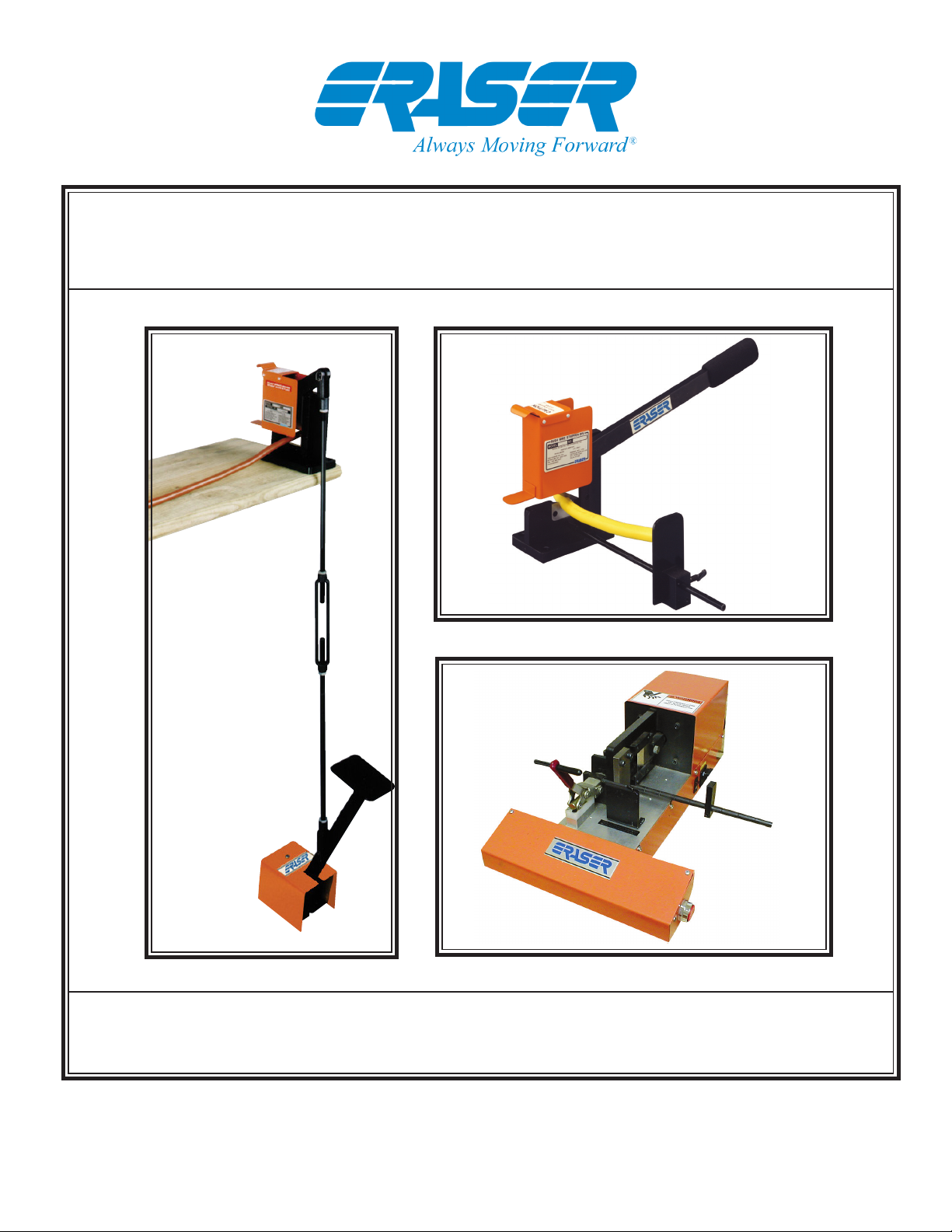
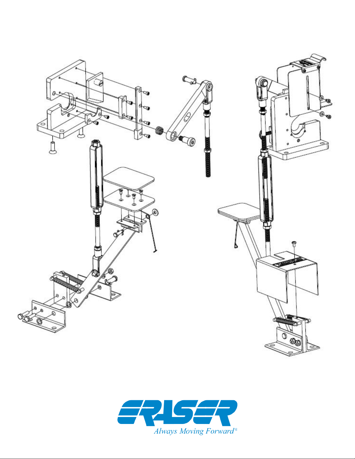
Models HC10/FC10/HCA20 Cable Cutters
Adjust the linkage assembly by use of the turn-
buckle until the footpedal stops traveling just before
hitting the oor. Once properly adjusted, tighten all
linkage jam nuts securely to lock the adjustment
in place. To install the length stop, screw one end
of one rod into the hole at the base of the FC10.
Add other rods as desired to the rst rod. Slide the
stop plate onto the rods and secure with the screw.
The two rods are marked at 1” increments to allow
consistent measurements up to 24”.
(Additional rods may be purchased, see ordering
information)
HCA20:
The HCA20 is shipped assembled except for the
strip length stop, 5/64” and 5/32” allen wrenches
which are packaged separately. The unit requires
a clean, dry, regulated air supply, of minimum 90
PSI and not exceeding 100 PSI.
Install the length stop rod by screwing it into the
threaded hole located below the lower blade
guide and in front of the stationary blade. The rod
is marked by 1” increments to allow consistant
measurements up to 12”. (Additional rods may
be purchased, see ordering information) Connect
the air supply to the unit, using a 1/4” n.p.t. male
connector. Locate the unit on the bench so that the
two nger switches are facing the operator. Attach
the power cord to the IEC connector at the back
of the HCA20. Plug the unit into the appropriate
properly grounded power supply, 115V 60Hz.
OPERATION:
NOTE: The HC10 and FC10 are designed to be
operated with a maximum of 35 lbs of force applied
by the operator to either the footpedal or operat-
ing lever. The HCA20 is designed to operate at a
maximum 100 PSI and conveys a force of 1200
lbs. on the material to be cut. The cutters are NOT
designed to cut wires or cables containing ferrous
metals, such as steel or steel alloys. Solid copper
single conductors of up to 4 AWG (21.1mmø) may
be cut. Cables or small bundles of wire up to 1 1/4”
(31.75mmø) in diameter may be cut, DEPENDENT
ON CONSTRUCTION. Cutting cables containing
many heavy strands of copper or aluminum may
not be possible, while cables containing many
small strands may usually be cut.
A good guide to use to determine a wire or cable’s
applicability for the cutter is whether or not it is
necessary to exert excessive force on the lever
or footpedal to shear the material. If unsure, send
a sample to the factory and we will determine its
applicability for the unit.
CAUTION:
The blades are extremely sharp! Be sure to keep
hands away from blades during cutting!
HC10:
To admit the material to be cut to the blades, lift the
guard up with the material itself, utilizing the lower
tab on the guard, or by hand with the upper tab.
Raise the operating lever to lift the upper guillotine
blade and seat the material on the lower curved
blade. The guard will slide down automatically
to protect the operator during cutting. Lower the
operating lever, applying force until the material
has been sheared.
FC10:
Follow above procedure for HC10 to admit mate-
rial to blades. Note, however, that the blades are
already open on the footpedal operated cutter. After
admitting material, step on the footpedal and push
it all the way down to shear the material. Bring
the footpedal back up gently with your foot. Do
not release the footpedal at the oor and allow
it to spring back up by itself, as this may cause
damage to the unit.
A conversion kit (IR8775) is available to convert
the Model HC10 into a footpedal operated Model
FC10 if desired. Instructions will be enclosed with
the conversion kit.
HCA20:
To load the material to be cut, open the holding
clamp and adjust the length stop to the desired
cut length using the 5/32” allen wrench provided.
Place the material in the blades, and clamp, up to
the length stop, and close the clamp. Adjust the
check nut on the back of the clamp until the mate-
rial is held with the desired pressure.
To operate the unit, adjust the air supply between
40 and 100 PSI depending on the material. Turn
the power switch on using the I/O switch located
on the side of the unit. To cut the cable, depress
Eraser Company Inc. • Syracuse, NY USA • Ph: 315-454-3237 • info@eraser.com • www.eraser.com • Fax 315-454-3090