p 4
Eraser Company Inc. • Syracuse, NY USA • Ph: 315-454-3237 • info@eraser.com • www.eraser.com • Fax 315-454-3090
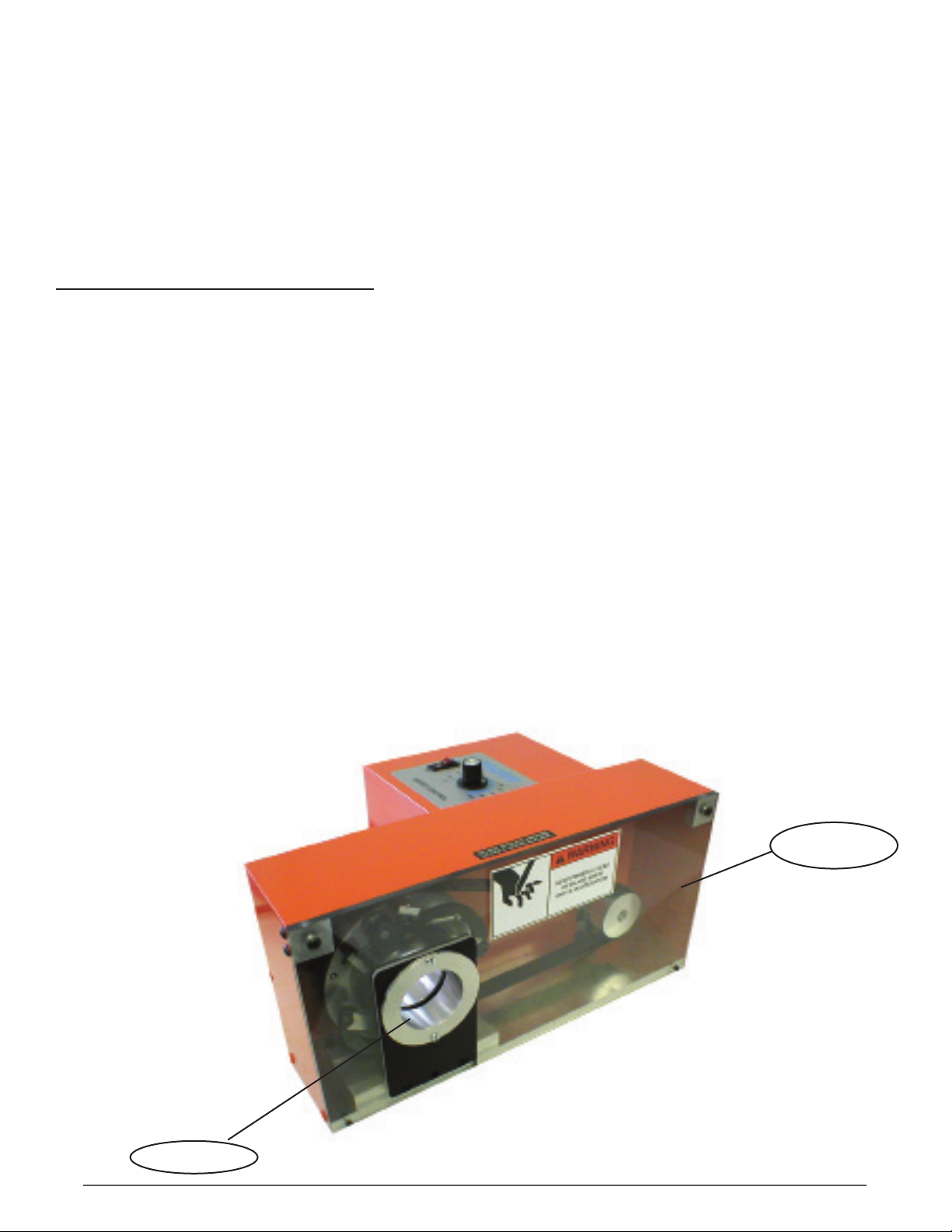
MODEL LFTC1 FLEXIBLE TUBE CUTTER
Place the Model LFTC1 on a sturdy workbench.
Insert the external threaded end of the lengthstop
rod into the threaded hole under the cutting head.
!CAUTION: BE SURE TO UNPLUG THE UNIT
BEFORE PERFORMING ANY SET-UP OR
MAINTENANCE.
BUSHING INSTALLATION:
To aid in bushing installation refer to picture 1 &
2.Ifdierentsizesofmaterialaregoingtobecut,
additional bushing sets must be ordered. There are
two guide bushings, the entrance and exit bushing,
loosen the 3/32” set screw with the Allen wrench
provided. Install the entrance bushing so it is as
close to the blade as possible.
!Caution: The blade must not come in contact
with the bushing. Retighten the 3/32” set screw
with the Allen wrench provided. Install the exit
bushing in the front cover with the two screws
provided.
ADJUSTING BLADE DEPTH:
Remove the plexiglass guard by removing the two
screws near the top of the plexiglass plastic guard.
Feed the tubing or cable into the entrance bushing
up to the cutting blade. Loosen the blade depth
adjusting screws (see picture 3) and adjust (rotating
the adjusting screw counterclockwise will adjust the
blade deeper) until the blade is completely through
the wall of the tubing or just before touching the
conductor in stripping applications. Retighten the
blade locking screw once the blade is set to the
correct depth. Cut quality will decrease if the blade
is allowed to cut further than necessary to sever the
tube. (Never allow the cutting blade to rotate further
than the center of the guide).
The blade holder open stop screws should be set so
that the material just clears when passed through.
Secure with the locking screws. This will improve cut
quality and decrease cycle time.
LENGTH STOP ADJUSTMENT:
Loosen the depth stop screw and adjust the length
stop block to the desired cut/strip length and
retighten it with the 5/32 Allen wrench. The cut
length can be readjusted until the desired length is
achieved. Longer cut lengths may be produced
by purchasing additional length stop rods, (part
#TR0176) which may be screwed directly into the
one provided with the machine. Reinstall the front
guard. See picture 4.
OPERATION:
Connect the power cord to the IEC connector, and
plug the unit into the appropiate power supply (either
115V 60Hz OR 230V 50Hz). Turn the machine on
using the I/O switch on the top of the unit. Set the
speed control to approximately 75% as a starting
point. Push the material through the input bushing
& exit bushing until it reaches the length stop block.
See pictures 1 & 2. Press the foot pedal. This will
activate the cutterhead to cut the material. When the
material is cut, release the footswitch. The cut time
will vary based on the material being cut. Cut times
will range from a fraction of a second to several
seconds. Lower machine speeds may cut better on
smaller or softer materials & higher speeds will be
necessary for thicker wall or harder materials. See
picture 2.
SCORING WIRE OR CABLE:
The LFTC1 may be used for precision scoring of
wire or cable jackets but may not be used for “slug”
removal without damaging the machine. Eraser’s
Model LS10 Cable Stripper (part #AR0240) or Model
LSA20CableStripper(part#AR6800)willfulllthis
need more productively than manual slug removal.
SET-UP FOR SCORING:
Install bushings per earlier procedure. Slide cable
into the input bushing up to the blades. Adjust
blades per blade adjustment but only to the
conductor diameter. Set the blade stop screw for
both blades. When running, be certain that the
blades have completely retracted before removing
product or damage to the product may result.
BLADE CHANGE OR REPLACEMENT:
NOTE:Ifthisisthersttimethebladehasbeen
dulled, it may be used again by turning the blade
around and using the other side. The cutting edge of
thebladeisoset,sotheblademaybeusedtwice.
See picture 3.
!CAUTION: Blades are very sharp. Be sure the
unit is unplugged before changing blades.
To replace the cutting blade, remove the front cover
with the 1/8” Allen wrench provided. Next, remove
one of the screws holding the blade in place with
the 5/32” Allen wrench provided and loosen the
other one. Slide the blade out from under the screw.