Eraser WC601B User manual

The Eraser Company, Inc.
PO Box 4961/ Oliva Drive
Syracuse, NY 13221, USA
Phone: (315) 454-3237 / Fax: (315) 454-3090
Website: www.eraser.com
E-mail: info@eraser.com
Eraser International Ltd.
Unit M, Hunting Gate
Andover SP10 3SJ, England
Phone: (01264) 351347 / Fax: (01264) 355030
Website: www.eraser-international.com
Email: [email protected]
Service and All Spare Parts Available
Operating Manual
Please Read Before Operating Unit
Always Moving Forward
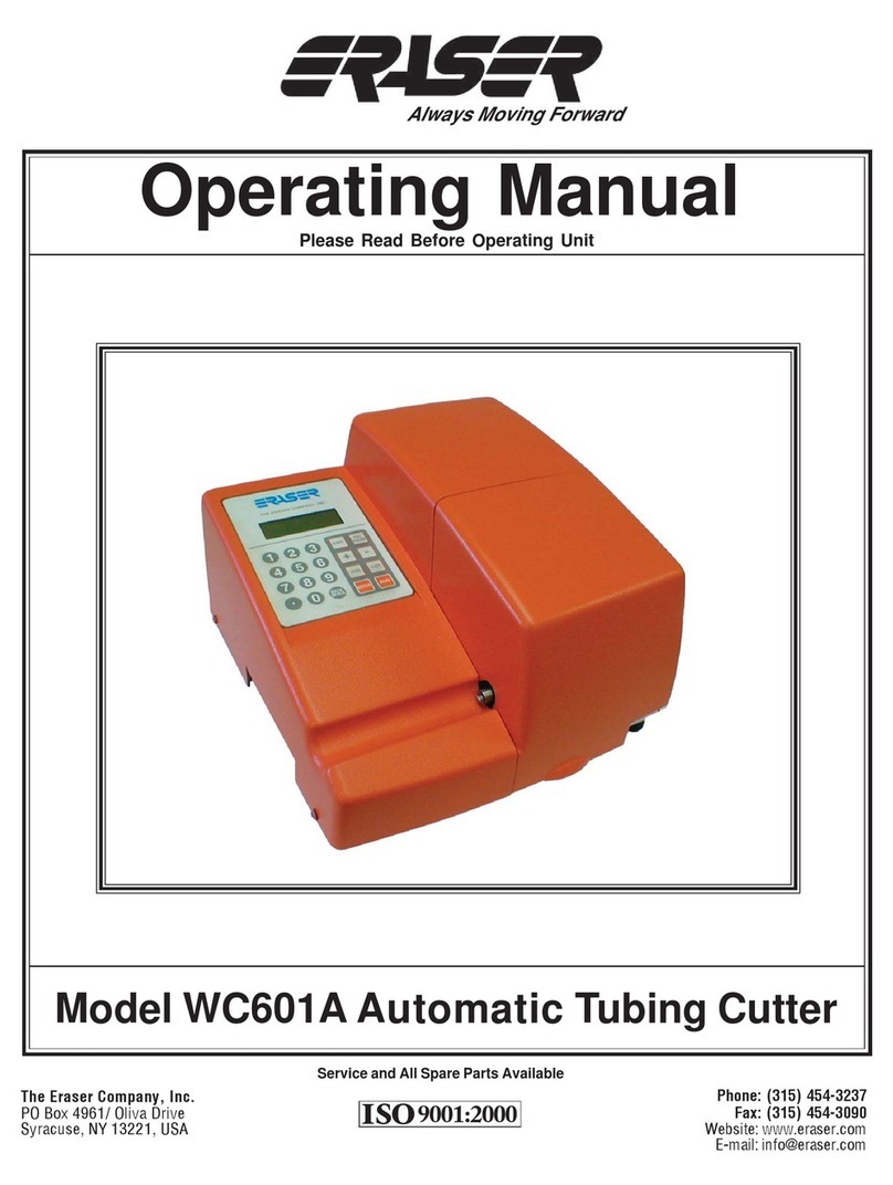
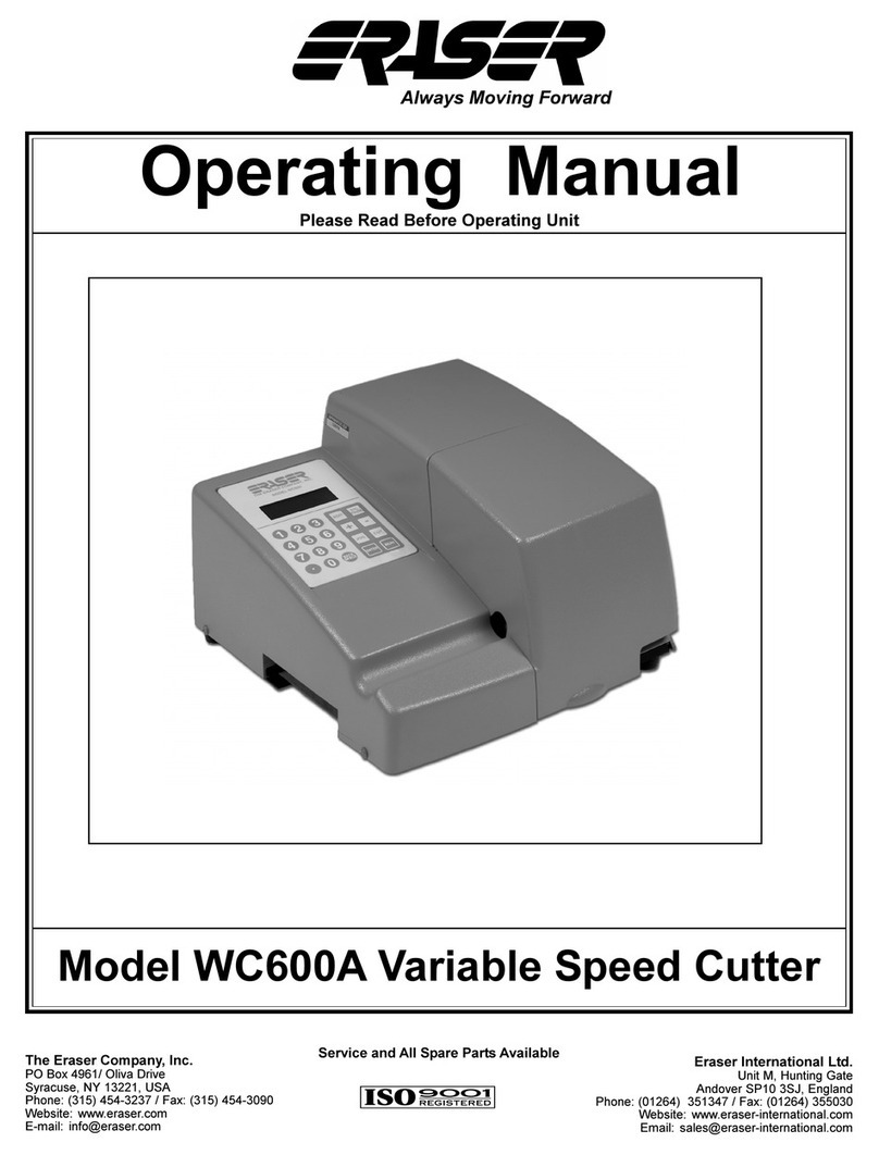
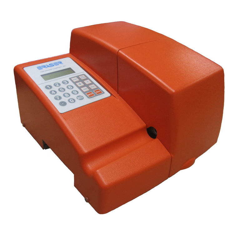
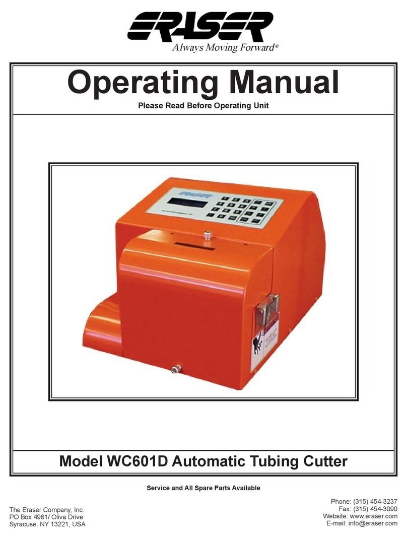
Model WC601B Rotary Tubing Cutter

AUTOMATIC ROTARY BLADE
TUBING CUTTER
Eraser Company Inc. • Syracuse, NY USA • Ph: 315-454-3237 • [email protected] • www.eraser.com • Fax 315-454-3090
Eraser International Ltd. • England • Ph:(01264)351347 • [email protected] • www.eraser-international.com • Fax (01264)355030
SPECIFICATIONS
Maximum Cut Length.......................................…23,300.00"
(233,000.0mm)
Minimum Cut Length............................……0.100" (2.54mm)
Maximum Material Size…..................….500” OD (12.7mmø)
Tolerances.......... At cut lengths of under 2” (51mm) on most
materials, the tolerance is ±0.01”(.25mm). All other cut
length tolerances are 1% or better dependent on material and
feed. Programmable length compensation of ±99% is built
into the unit to accomodate unusual materials. Squareness
of cut is 0-2 degrees.
Batching...................……Up to 99 programmable batches
Kits.......................................Up to 10 programmable kits
Blades.................……Razor type double beveled steel blade
Feed....................................Dual driven adjustable belt feed
Bushings.........…Purchased separately. Customer material
sample is required to drill bushings.
Counter...........................................................…0-999,999
Power..................................………115V 60Hz or 230V 50Hz
Decibel Rating...............................................…….60 db(A)
Size....................................................…...14” x 13” x 8.75”
(356mm x 330mm x 222mm)
Weight.....................................................26 lbs. (11.8 Kg)
ORDERINGINFORMATION
AR7131 (WC601B)………..................Variable speed rotary
tubing cutter, 115V 60 Hz
AR7132 (WC601B)………..................Variable speed rotary
tubing cutter, 230V 50 Hz
AR7133 (WC601B)….........…….........Variable speed rotary
tubing cutter, 230V 60 Hz, UK plug
IR1017…………....…………...........Set of custom bushings
for WC601B (Send material for sizing)
PR0232...................................One replacement feed belt
(2 necessary per unit)
PG0677......................One replacement drive belt for WC601B
Feed Rate:
There are nine selectable feed rates. In addition, cut time and cut
speedoftherotaryheadareselectable.Productionratesarevariable
by length of cut pieces, feed rate and cut speed and time.
Production Rates:
There are nine selectable belt feed rates and cut head rotation
speeds as well as an infinitely adjustable time parameters.
Production rates vary, most importantly, according to difficulty
of cutting (i.e. cut time) and, to a lesser degree, difficulty in
transport (i.e. how much material is being feed, how heavy of
a spool, how sophisticated the pre-feed system, etc.). If
production rates are critical, send 20 feet or more (most
accurate determination if you send the spool intended to use
in production) to our lab for cut testing. The following table
shows some typical production rates. These rates were devel-
oped using an average cut time for a typical range of materials.
1 sec. cut time Length 2" Length 6" Length 10" Length 20" Linear speed
Feed Rate # 51mm 152mm 254mm 508mm (feed belts)
5.7 in./sec
(144mm/sec)
8.0 in./sec
(203mm/sec)
12.2 in./sec
(309mm/sec)
16.6 in./sec
(421mm/sec)
20.8 in./sec
(528mm/sec)
25.1 in./sec
(637mm/sec)
29.3 in./sec
(744mm/sec)
33.4 in./sec
(848mm/sec)
39.8 in./sec
(1011mm/sec)
Various Feed Lengths in pcs./hour
1 1700 1300 1100 700
800
3 2050 1800 1500 1100
2 1900 1500 1200
1300
5 2150 1950 1750 1400
4 2100 1900 1650
1450
7 2200 1950 1900 1550
6 2150 1950 1800
1650
9 2200 1950 1900 1650
8 2200 1950 1900

OPERATION
Eraser Company Inc. • Syracuse, NY USA • Ph: 315-454-3237 • [email protected] • www.eraser.com • Fax 315-454-3090
Eraser International Ltd. • England • Ph:(01264)351347 • [email protected] • www.eraser-international.com • Fax (01264)355030
4 LINE KEYPAD DISPLAY
FEED ROLLER
TENSION ADJUSTER EXIT
BUSHING
FEED
BELT
INPUT
BUSHING
WC601B CUTTER HEAD AND FEED BELTS

Model WC601B Bushing Installation Drawing
1. Install the entrance bushing chamfer side out (to the left). Make certain it does not interfere with the feed belts
when they are fully closed. Tighten the set screw to lock its position.
2. Insert chamfered side of head bushing toward belt feed. Position it so that the end opposite the chamfer is as
close as possible to the blade without interference when cutter head is engaged. Lock its position with the set screw.
3. Adjust blade depth stop before installing the exit bushing. Insert the exit bushing chamfer side out (to the right).
Position it so that the end opposite the chamfer is as close as possible to the blade without interference when cutter
head is engaged. Lock its position with the set screw.

WARNING
DO NOT OPERATE TOOL UNTIL YOU HAVE READ
THOROUGHLY, AND UNDERSTAND COM-
PLETELY, ALL INSTRUCTIONS, RULES, ETC. ON
THIS PAGE, AND IN THE OPERATING MANUAL.
WHEN USING ELECTRIC TOOLS, BASIC SAFETY
PRECAUTIONS SHOULD ALWAYS BE FOLLOWED
TO REDUCE RISK OF FIRE, ELECTRIC SHOCK,
AND PERSONAL INJURY, INCLUDING THE FOL-
LOWING:
GROUNDING INSTRUCTIONS
In the event of a malfunction or breakdown, grounding provides
a path of least resistance for electric current to reduce the risk
of electric shock. This tool is equipped with an electric cord
having an equipment-grounding conductor and a grounding
plug. The plug must be plugged into a matching outlet that is
properly installed and grounded in accordance with all local
codes and ordinances.
Do not modify the plug provided – if it will not fit the outlet, have
the proper outlet installed by a qualified electrician.
Improper connection of the equipment-grounding conductor
can result in a risk of electric shock. The green conductor with
or without yellow stripes is the equipment-grounding conduc-
tor. If repair or replacement of the electric cord or plug is
necessary, do not connect the equipment-grounding conduc-
tor to a live terminal.
Check with a qualified electrician or service personnel if the
grounding instructions are not completely understood, or if in
doubt as to whether the tool is properly grounded.
Use only 3-wire extension cords that have 3-prong grounding
plugs and 3-pole receptacles that accept the tool’s plug.
Repair or replace damaged or worn cord immediately.
GENERAL INSTRUCTIONS
REMOVE ADJUSTING KEYS AND WRENCHES.
Form habit of checking to see that keys and adjusting
wrenches are removed from tool before turning on.
KEEP WORK AREA CLEAN. Cluttered areas and benches
invite accidents.
DON’T USE IN DANGEROUS ENVIRONMENTS.
Don’t use power tools in damp or wet locations, or expose
them to rain. Keep work area well lighted.
ALWAYSUSESAFETYGLASSES.Everydayeyeglasses
only have impact resistant lenses; they are NOT safety
glasses. Also use face or dust mask if cutting operation is
dusty.
WEAR PROPER APPAREL. Do not wear loose clothing,
gloves, neckties, rings, bracelets, or other jewelry that might
get caught in moving parts. Nonslip footwear is recom-
mended. Wear protective hair covering to contain long hair.
DON’T OVERREACH. Keep proper footing and balance
at all times.
MAINTAIN TOOLS WITH CARE. Keep tools sharp and
clean for best performance and to reduce the risk of injury.
Follow instructions for lubricating and changing accessories.
DISCONNECT TOOL before servicing; when changing
accessories, such as blades, wheels, cutters, and like.
USE RECOMMENDED ACCESSORIES. Consult the
operating manual for recommended accessories. The use of
improper accessories may cause risk of injury to persons.
CHECK DAMAGED PARTS. Before further use of the
tool, a guard or other part that is damaged should be carefully
checked to determine that it will operate properly and perform
its intended function. Check for alignment of moving parts,
binding of moving parts, breakage of parts, mounting, and any
other conditions that may affect its operation. A guard or other
part that is damaged should be properly repaired or replaced.
DO NOT EXCEED THE MAXIMUM MATERIAL SPECIFICA-
TIONS.
DO NOT OPERATED UNIT WITHOUT GUARDS IN PLACE
OR GUARDS NOT IN WORKING ORDER.
DO NOT PERFORM MAINTENANCE OR ADJUSTMENTS
WITH POWER ON.
DO NOT PLACE FINGERS OR APPENDAGES IN OR NEAR
OPENINGS IN GUARDS.
DO NOT RUN UNIT WITH INCORRECT LINE VOLTAGE.
REFER TO LABEL PLACED OVER I/O SWITCH.
DONOT ALLOWUNTRAINED ORUNQUALIFIED PERSON-
NEL TO OPERATE UNIT.
DO NOT DEFEAT ANY OF THE SAFETY FEATURES DE-
SIGNED INTO THE UNIT.
IMPORTANT:
No liability will be incurred by The Eraser Company
for injury, death, or property damage caused by a
product which has been set up, operated, and/or
installed contrary to Eraser’s written instruction
manual, or which has been subjected to misuse,
negligence, or accident, or which has been repaired
or altered by anyone other than Eraser, or which has
been used in a manner or for a purpose for which the
product was not designed.
IMPORTANT SAFETY INSTRUCTIONS
READ ALL INSTRUCTIONS

MODEL WC601B ROTARY TUBING CUTTER
OPERATING INSTRUCTIONS
SET-UP:
The WC601B is supplied with one 3/32" Allen wrench, one
7/64" Allen wrench and one 5/64" Allen wrench.
CAUTION:
The WC601B blade is intended for use on soft flexible tubing.
However, some rigid tubing and some wire may be cut. The
blade is a very thin, sharp blade, and caution should be used
when handling it.
The WC601B is equipped with carrying handles on the sides
of the housing. Place the unit on a sturdy workbench with the
right corner of the exit opening even with the right corner of the
bench. Short and long cut lengths will drop out the side of the
exit bushing. Material collection bins can be placed to collect
the cut material as it exits the unit. If using the DE700 or any
other tensioning dereeler, place the dereeler to the left side
of the unit at least 24" from the entrance bushing in a straight
line, and align the lower pulley with the entrance bushing. If
using the DE700, refer to the operating manual for further set
up details.
BUSHING INSTALLATION:
To aid in bushing installation refer to the drawing. The unit
requires one set of custom guide bushings. There are three
guide bushings, the entrance, head (or middle) bushing, and
exit bushing. The entrance and exit bushings are the same
size, and the head (middle) bushing is longer. First install the
larger head bushing. Locate the chamfered side of the
bushing; this is the side that goes in first. Slide the bushing
in through the exit bushing mounting plate, past the blade.
Then slide the head bushing back toward the blade, without
hitting the blade. Manually close the blade and check that the
head bushing is not touching the blade. Tighten the head
bushing in place with set screw. Insert the exit bushing in
place with the chamfer facing out away from the blade.
Manually close the blade, position the exit bushing as close
to the blade as possible. Tighten exit bushing in place. Make
certain that the blade moves freely by manually closing the
blade. Reposition the bushings if necessary. Install the
entrance bushing (chamfer side out) making certain that it
does not interfere with the belts when they are in the fully
closed position. Keep the bushings as close as possible to
the blade without the cutting edge closing on to the bushing.
This will provide the squarest cut and allow the shortest
pieces of tubing to be run. Bushings that are not close to the
blade will allow jamming of short cut pieces.
Connect the power cord to the IEC connector, and plug the
unit into the appropriate power supply (either 115V 60Hz OR
230V 50/60Hz).
Place the material to be cut on the dereeler. Turn the
WC601B on using the I/O switch on the back side of the unit.
To open the front cover, lift the hinged cover that is magneti-
cally latched to the base. The display will read “cover open
system disabled” if the cover is open and if the unit is running.
Open the belt feed by turning the knurled belt feed adjusting
knob counter clockwise on the belt feed. Feed the tubing
through the entrance bushing, between the belts into the
head bushing and through the exit bushing. If the cover is
open, the material cannot be fed past the exit bushing, until
the cover is closed. To tighten the upper and lower belts,
simply turn belt adjusting knob clockwise. The belt roller
adjustment will prevent tubing from being compressed, but it
can also affect length. If the material is slippery, more tension
may be applied to the belt feed by turning the tension
adjusting knob clockwise. Apply only enough tension to
transport the material. Do not over-tighten the belts. Over
tightening the belts may cause the material to crush thus
creating excessive drag in the transport bushing. The belts
should be adjusted by tightening them until the material
(tubing) can no longer be pulled between the belts. More belt
pressure may be added if the cut lengths are inconsistent.
Once material has been fed through the bushings and belt
tension is set tighten the cork nut, close the cover and use
the JOG button to feed the material manually, and the CUT
button to cut it off. The unit now is ready for programming.
Note: The material can be fed manually as described above
or by jogging the material through the bushings. To feed with
the cover closed, press the JOG button to enter the manual
mode and press the JOG button again to jog the material
through the entrance/cut bushings. If the material does not
feed, it can be inserted with the guard open. If in the manual
mode, the unit can jog, rotate and cut the material. Press the
JOG or CUT keys to move or cut material.
PROGRAMMING:
START UP: When the unit is turned on, the controller will
report that it is initializing and display “The Eraser Co/
WC601B Kit”. The system will then automatically display the
batch screen:
Do one of these: 0 (Enter 1)
Enter 0 for no batch
Enter . for kit
Next new batch #__
The number on the first line will be the last batch run, or in this
case, 0, since this is the first run since the system was
powered up. A “batch” is a set of parameters for a quantity of
one length to be cut (i.e. the cut length, the feed rate, the cut
time, the cut speed, quantity and the unit of measure). The
number on the last line is the next available batch that has not
yet had parameters stored (clean memory location). The
system requires that batches be created in sequence, so
numbers higher than the number on the last line will not be
accepted. As batches are created, the number on the last line
will increase, until the current maximum of 99 batches is
reached.
Press ENTER to select the default, or type in a new number.
The line being edited will display a blinking cursor. If “0” is
selected, all parameters will be set to zero, and will need to
be entered manually. Parameters entered while using batch
0 are never stored (i.e. the “0” batch is a scratch memory
location). Parameters for all other batches are stored, so the
next time that particular batch is called, those parameters will
be presented as defaults. If any parameters are edited, the
new values will be stored for the next time that batch is
entered. All batches that have parameters stored can be
edited by entering the desired batch number.
CREATING A NEW BATCH:
Enter the number on the last line of the batch prompt screen,
in this case 1. The first edit screen will appear:
Length units IN #1 (Use + or - key to change to mm)
Length 0.00
Length compensation 0
Quantity 0
The current batch number is shown beside the # at the top
right. The cursor will be flashing just before the in (inch),
indicating that the field is currently editable. In general, the
line being edited will display a blinking cursor. Press ENTER
to accept the default of inches, or press the “+” or “-“ key to
toggle to mm, for millimeters, then press ENTER to store
mm. Each time ENTER is pressed, the cursor advances to
the next parameter.
Enter a value for the length parameter. If ENTER is pressed
accidentally before a value is entered, a long error beep will
sound, otherwise the entered value will be stored. If a mistake
is made, press the BS key to back space over the entry. If the
enter key has been pressed, press the ESC key and start
over. All values entered so far will have been stored, so you
would only have to press ENTER until you returned to the
place where you wanted to make a change-the values would
not have to be entered again. Any value between .01 and
23,300 may be entered. This allows for 5 digits before the
decimal place and 2 digits after. In mm mode, only 1 decimal
place is allowed after the decimal point and 6 digits in front of
the decimal.
Due to variations in materials, pre-feed systems and belt
tension, actual cut length may vary from the inputted length
by a proportional amount. The WC601B incorporates a length
compensation feature to provide an easy adjustment in these
cases. The length can be compensated +/-1% to +/- 99% of
the inputted length. The length compensation display will
show (-) for a negative value. Example: If 10" (254mm) is
entered as the desired length, but the actual cut pieces
measure 9.8" (249mm), a length compensation of +2% will
increase the cut length by .200 (5mm) to the desired 10"
(254). The default is 0, or the “+” or “-” keys may be used to
add or decrease length compensation of plus or minus 1 -
99% of the inputted length. NOTE: Often it will not be known
if length compensation is needed until after a trial run is
completed. When programming a batch, leave the field at 0
and edit the batch later if necessary to add length compen-
sation. Once a value has been entered, or if the default of 0
is to be used, press ENTER. The length compensation will
remain with the batch program. An alternate, more accurate,
method would be simply to enter the desired cut length,
measure the error and add/subtract the error to/from the
targeted length (e.g. a desired 10.00” is entered into the
length parameter; a measured 9.82” is cut. The operator
compensates for this by adding 0.18” to the targeted cut
length value. The new cut length value becomes 10.18”).
ENTER THE QUANTITY OF CUT DESIRED - UP TO 999,999.
Rate Screen:
Feed Rate 3 #x (Enter 1 thru 9, rate #3 is default.
x=current batch number)
Initial Rate 1500
Final Rate 8600
Acceleration 18
After the quantity is entered, the rate edit screen appears.
Press “+” or “-” to increment or decrement the feed rate value.
Alternately, the desired feed rate may be entered manually
(any number between 1 and 9). As the value is changed, the
rate values are updated to show what values are active for that
feed rate. The following table represents the maximum speed
at any feed rate of the feed belts:
NOTE: The slower the feed rate, the more accurate in length
the cut pieces will be. It is advised to start with the lowest feed
rate and check results, then adjust the feed rate if desired.
Cutter Screen:
Cutter Parameters
Cut Speed 6 (Enter 1 thru 9, 6 is default)
Cut Time 1.000 (Enter0.1toanynumberofseconds,1isdefault)
The cut speed controls the speed and pressure at which the
rotary blade cuts through the material. If material does not cut
completely through, increase the speed control. If cut is not
clean enough, decrease the speed control. The cut time can
be changed for materials of different hardness. Average cut on
times are from 0.5 second to 2 seconds. The blade speed and
cut time should be set as low as possible to give the best
possible cut. There are 9 cut speeds that allow incremental
adjustment of the rotary speed of the cut head (typically 750
RPM to 1900RPM).
After the Cut Time is entered, the display under “Cut Time
x.xxx” will show: “Press Run to Start”. Press RUN or ENTER
to begin the cutting cycle of the tubing cutter.
Run Screen:
Feed Rate # Linear Speed (in/sec) Linear Speed (mm/sec)
1 5.7 144
2 8 203
3 12.2 309
4 16.6 421
5 20.8 528
6 25.1 637
7 29.3 744
8 33.4 848
9 39.8 1011

Pieces 10 #x (where x=batch#)
Length 1.000 IN
Feed Rate 3 10 (compensation factor)
Pieces Left nnnn (where n=pieces to be processed)
If the compensation factor is non-zero, its value will be printed
on the same line with the feed rate. The system will wait till
the RUN or ENTER key is pressed. Once started, the number
of pieces left is updated as the run progresses.
KIT FEATURE
The WC601B also has a kit feature: this allows a collection
(or set) of batches to be run sequentially. For example, if
batches 4, 5 and 6 are setup and defined to run a 6” piece
(quantity 1, feed rate #3, 0 compensation), 8” piece (quantity
3, feed rate #2, compensation 0) and a 2” piece (quantity 1,
feed rate 5, compensation 0) respectively, a kit can be defined
to be batches 4, 5 and 6 (not necessarily in that order). The
WC601B will then feed and cut a 6” piece, 3 8” pieces and a
2” piece. The quantity of kits (i.e. the number of sets of
lengths) is entered when defining a kit.
The default idle screen below:
Do one of these: 0
Enter 0 for no Batch
Enter. for Kit
Next new batch number #__
Allows the user to enter kit mode by a “.” key press. The
screen will then go to the kit selecting screen:
Select Kit #:__ (this variable displays last kit # ran since
power-up)
Enter 0 to return
Next new Kit #__ (this variable displays the first undefined kit #)
At this point the user has 3 options. 1) The user selects a kit
already defined and assigned a number. The screen then
moves on to the first kit editing screen, displaying the first
batch in that kit [see kit editing screen below]. 2) The user can
back out of the kit mode (back to first screen) by choosing “0”
and ENTER. 3) The user can define a new kit. This looks
similar to the kit editing screens. Assuming that batches 4,
5, and 6 are already defined as above (Batch 4=1 piece @ 6”,
batch 5=3 pieces @ 8” and batch 6=1 piece @ 2”) the kit
editing screens allow the user to simply enter a batch number
for each step of the kit:
Select batch#__ (default=0 for undefined kit, first batch #
otherwise)
Kit __ Index 1 (index = batch order)
Enter # to change
Len=______ Quant=_____ (displays 0 if new kit, batch
parameters otherwise)
If kit 1 is undefined, then we have:
Select batch#0
Kit 1 Index 1
Enter # to change
Len=0.00 Quant=0
The user then selects the first batch in a kit (for example, batch #4)
Select batch#4
Kit 1 Index 1 (the index increments to 2, the second
batch in a kit)
Enter # to change
Len=6.00 Quant=1
The user presses ENTER and then selects batch #5:
Select batch#5
Kit 1 Index 2
Enter # to change
Len=8.00 Quant=2
The user presses ENTER and then selects batch #6:
Select batch#6
Kit 1 Index 3
Enter # to change
Len=1.00 Quant=4
The user presses ENTER:
Select batch#0
Kit 1 Index 4
Enter # to change
Len=0.00 Quant=0
If the user leaves the 0 as a batch number and then presses
ENTER, then the kit is now defined. A “0” batch number ends
the definition of the kit. If the user presses another #, then
there will be another batch in the kit and the index increments.
60 batches per kit is the maximum that can be defined.
Eventually the user defines a last batch in a kit:
Enter quantity of
Kits:0 (default=0 in new kit, last quantity in a defined kit)
Enter 0 for Manual
Or # for Auto mode
The quantity defaults to the quantity defined when kit was
created or to 0 if a new kit. If manual mode is desired (i.e. a
button press required to advance each piece), then a “0” is
entered. Automatic mode (the machine runs continuously to
complete the kit) requires the operator to enter a number. An
existing kit can always be edited (i.e. add/delete or change
batches within a kit). Batches always need to be defined
before being entered into a kit.
PAUSE FUNCTIONS
To interrupt a run at any time, depress the PAUSE/ESC key
once to stop the unit. Press the ESC key again to exit the
batch or kit. (Depressing the ESC key twice quickly will stop
the unit immediately.) When the key is released, the mes-
sage “paused” will appear on the bottom line of the display.
The system can be opened and adjusted only if the material
does not extend past the exit bushing. Then close and restart
by pressing the RUN or ENTER key. If the material is

extending past the exit bushing, press the CUT key to cut and
remove the cut piece to allow the guard to open. While
paused, the length compensation may be edited with the “+”
or “-” keys. Material may be fed using the JOG key. By
depressing the JOG key, material will be fed with the length
being displayed. Each time a manual cut is performed, the
length is reset back to zero. The feed rate may be changed
while paused by pressing EDIT and selecting a new feed rate.
Press ESC/PAUSE when paused to abort the run and return
to the Batch Prompt screen. When the run is complete, the
message Run Complete will appear on the bottom line.
OPERATION:
The WC601B will not operate unless the front cover is closed.
If the cover is opened during a run the unit will stop and the
screen will display “cover open/system disabled.” The sys-
tem cannot be run until the cover is closed and the display
reads “ready to run/any key continues.” Pressing the ESC or
PAUSE key will return to the run screen in the pause mode.
Pressing the RUN key will immediately resume the run.
POWER FAILURE:
In case of a power failure, the WC601B will be reinitialized and
will not start unexpectedly. All parameters stored in a batch
program will remain in memory. Parameters in the 0 batch will
be lost. The controller is protected by a fuse located in the
back of the housing just above the IEC connector.
BLADE CHANGE, OR REPLACEMENT AND
BLADE DEPTH ADJUSTMENT
CAUTION: BE SURE UNIT IS UNPLUGGED BEFORE
CHANGING BLADES.
To replace the blade, with the front cover open, find the exit
bushing and loosen the set screw holding it in place with the
5/64" Allen wrench provided. Slide the exit bushing to the right
and remove. Next, remove one of the screws holding the blade
in place, with the 3/32" Allen wrench provided and loosen the
other one. Slide the blade out from under the screw and
washer. Replace blade, screw, and tighten.
NOTE: If this is the first time the blade has been dulled, it may
be used again by turning the blade around and using the other
side. The cutting edge of the blade is offset, so the blade may
be used twice.
To adjust the depth of the blade, locate the socket head cap
screw located on the rotary head and loosen the locking
socket head set screw, which locks the socket head cap
screw in place, using the 5/64" Allen wrench provided. To
adjust the blade deeper, turn the socket head cap screw
using the 7/64" Allen wrench provided counterclockwise. To
raise the blade, turn the screw clockwise. NEVER ALLOW
THE BLADE TO GO PAST CENTER OF BUSHING! Blade
depth is properly set when the blade is slightly deeper than
the inside wall of the tubing being cut. After adjusting the
blade depth, tighten the locking socket head set screw to
keep the blade from moving.
MAINTENANCE:
CAUTION: BE SURE TO UNPLUG THE UNIT BEFORE
PERFORMING ANY MAINTENANCE. BE SURE TO EM-
PLOY APPROPRIATE ANTI-STATIC PROCEDURES/DE-
VICES WHEN DISASSEMBLING AND ASSEMBLING UNIT.
1. Check the blade for wear after prolonged use. Due to the
number of different materials, this maintenance should be
reviewed by your plant maintenance personnel and adjusted
accordingly.
2. No other maintenance is required for the units.
TROUBLESHOOTING:
PROBLEM: The blade does not move and is stuck in a closed
position.
SOLUTION:
Adjust the blade as described in the blade change or
replacement section: Head or exit bushings may be adjusted
too close to the blade.
PROBLEM:Material doesnotfeedproperlythroughthebushings.
SOLUTION:
1. Tighten the belt-feed adjusting knob clockwise to increase
the belt pressure on the material.
2.Checkthe blade andbushingposition. Readjust ifnecessary.
PROBLEM: Display does not function.
SOLUTIONS:
1. Check the fuse located in the rear of the housing. Only use
the recommended fuses. If the fuse continues to blow after
replacement, return the unit to the factory for repair.
2. Check the on/off switch.
PROBLEM: Poor quality cut or no cut.
SOLUTIONS:
1. Check that the blade is not dull. Replace or turn if
necessary.
2. Make certain the head and exit bushings are close enough
to the blade on both sides and chamfers are facing out.
3. Check blade depth adjustment.
4. Lower the motor cutter speed and increase the cutter on time.
5. Check cut motor brushes. Replace if less than ¼” length.
PROBLEM: Erratic cut lengths.
SOLUTIONS:
1. Check dereeler to make certain material is feeding correctly.
2. Make certain proper tension is applied to belt feed.

Batch #1
Length=xxx.xx
Comp. Factor=x
unit of measure=inch
quantity=xxx
feedrate=x
Memory organization of batches and kits
Batches are any number of pieces cut to 1 length:in
memory, the WC601A uses 5 variables in an array: the
length, the unit of measure, the compensation factor, the
quanitity of pieces to cut and a feed rate.
Kits are a collection of batches [i.e. any number of of
pieces cut to many different lengths (maximum of 60)].
Batch #4
Batch #5
Batch #6
Batch #0
Batch #0
Batch #0
Batch #0
Kit #1 Quantity=50
Index 1
Index 2
Index 3
Index 4
Index 5
Index 6
Index 60
Kit #2 Quantity=x
Index 3
Index 60
Index 6
Index 4
Index 5
Index 1
Index 2
Batch #x
Batch #0
Batch #0
Batch #x
Batch #x
Batch #x
Batch #x
Batch #0
Index 4
Index 60
Index 5
Index 6
Batch #0
Batch #0
Batch #0
Kit #9 Quantity=0
Index 2
Index 3
Index 1
Batch #0
Batch #0
Batch #0
99 Batches
9 Kits
Each batch stores
parameters
to cut one length any number
of times, at one of nine feed
speeds and a correction
factor associated with it.
Up to 60 batches
per kit allowed
Length=xxx.xx
Comp. Factor=x
unit of measure=inch
quantity=xxx
feedrate=x
Batch #2
Length=xxx.xx
Comp. Factor=x
unit of measure=inch
quantity=xxx
feedrate=x
Batch #3
Length=6.00
Comp. Factor=0
unit of measure=inch
quantity=1
feedrate=3
Batch #4
Length=8.00
Comp. Factor=0
unit of measure=inch
quantity=3
feedrate=2
Batch #5
Length=2.00
Comp. Factor=0
unit of measure=inch
quantity=1
feedrate=5
Batch #6
Length=xxx.xx
Comp. Factor=x
unit of measure=inch
quantity=xxx
feedrate=x
Batch #99
Memory Organization of Batches and Kits
Batches are any number of pieces cut to 1 length. In memory, the WC601B uses 5 variables in an array:
the length, the unit of measure, the compensation factor, the quantity of pieces to cut, and the feed rate.
Kits are a collection of batches [i.e.: any number of pieces cut to many different lengths (maximum of 60)].
Eraser International Ltd.
Unit M, Hunting Gate
Andover SP10 3SJ, England
Phone: (01264) 351347 / Fax: (01264) 355030
Website: www.eraser-international.com
Email: [email protected]
The Eraser Company, Inc.
PO Box 4961/ Oliva Drive
Syracuse, NY 13221, USA
Phone: (315) 454-3237 / Fax: (315) 454-3090
Website: www.eraser.com
E-mail: info@eraser.com
IR1563
4/04
Table of contents
Other Eraser Cutter manuals

Eraser
Eraser WC600A User manual

Eraser
Eraser WC601A User manual

Eraser
Eraser LFTC1 User manual

Eraser
Eraser FTC1 User manual

Eraser
Eraser WC601D User manual

Eraser
Eraser WC601A User manual

Eraser
Eraser WC600D User manual

Eraser
Eraser RTC1 User manual

Eraser
Eraser HC10 User manual

Eraser
Eraser CCB100 User manual