SET-UP:
The WC600D is supplied with one 3/32" Allen wrench,
one 5/32" Allen wrench and one 5/64" Allen wrench.
Bushing must be purchased separately.
CAUTION:
The WC600D blade is intended for use on soft flexible
tubing. However, some rigid tubing and some wire may be
cut. The blade is a very thin sharp blade and caution
should be used when handling it.
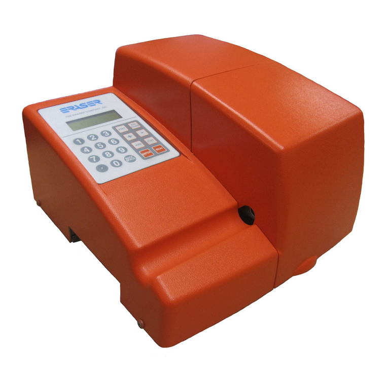
Place the Model WC600D on a sturdy workbench with the
right corner of the exit opening even with the right corner
of the bench. Short and long cut lengths will drop out the
side of the exit bushing. Material collection bins can be
placed to collect the cut material as it exits the unit. If
using the DE700 (or any other tensioning dereeler), place
the dereeler to the left side of the unit, at least 24" from the
entrance bushing in a straight line and align the lower
pulley with the entrance bushing. If using the DE700, refer
to their operating manual for further set up details.
BUSHING INSTALLATION:
To aid in bushing installation refer to the drawing. If
different sizes of material are going to be cut, additional
bushing sets may be ordered. There are three guide
bushings, the entrance, head, (or middle) bushing, and
exit bushing. First install the longer head bushing. Locate
the chamfered side of the bushing, this is the side that
goes in first. Slide the bushing in as close as possible to
the belt feed and back toward the blade, without hitting the
blade. Manually close the blade and check that the head
bushing is not touching the blade. Tighten the head
bushing in place. Insert the exit bushing in place. Manu-
ally close the blade, position the exit bushing as close to
the blade as possible. Tighten exit bushing in place. Make
certain that the blade moves freely by manually closing
the blade. Reposition the bushings if necessary. Install
the entrance bushing (chamfer side out) making certain
that it does not interfere with the belts when they are in the
fully closed position. Keep the bushings as close as
possible to the blade. This will provide the squarest cut
and allow the shortest pieces of tubing to be run. Bush-
ings that are not close to the blade will allow jamming of
short cut pieces.
Connect the power cord to the IEC connector, and plug
the unit into the appropriate power supply (either 115V
60Hz OR 230V 50Hz).
Place the material to be cut on the dereeler. Turn the
WC600D on using the I/O switch on the back side of the
unit. To open the front cover, unscrew the top and front.
The display will read “cover open system disabled” if the
cover is open or if the unit is in a run program. Back out
the belt feed adjusting knob by turning the adjusting knob
counter clockwise on belt roller tension adjuster. Feed the
tubing through the entrance bushing, between the belts
into the head bushing and through the exit bushing. To
tighten the upper and lower belts, simply turn belt adjust-
ing knob clockwise. The belt roller adjustment will prevent
tubing from being compressed, but it can also affect
length. If the material is slippery, more tension may be
applied to the belt feed by turning the tension adjusting
knob clockwise. Apply only enough tension to transport
the material. Do not over- tighten the belts. Over tightening
the belts may cause the material to crush thus creating
excessive drag in the transport bushing. The belts should
be adjusted by tightening them until the material (tubing)
can no longer be pulled between the belts. More belt
pressure may be added if the cut lengths are inconsistent.
Once material has been fed through the bushings and belt
tension is set, close the cover and use the jog button to
feed the material manually, and the cut button to cut it off.
The unit now is ready for programming. Note: The material
can be fed manually as described above or by jogging the
material through the bushings. To feed with the cover
closed, press the Jog button to enter the manual mode
and press the Jog button again to jog the material through
the entrance/cut bushings. If the material does not feed,
it can be inserted with the guard open. If in the manual
mode the unit can jog, rotate and cut the material. Press
the jog or cut keys to move or cut material. The speed of
the jog and cutter head will be determined by the last
inputted variables placed in the microprocessor.
PROGRAMMING:
START UP: When the unit is turned on, the controller will
report that it is initializing and display The Eraser Co/
WC601B. The line being edited will display a blinking
cursor. The system will then automatically display the
batch screen:
Do one of these: 0 (Enter 1)
Enter 0 for no batch
Enter known batch #__
Enter new batch #__
The number on the first line will be the last batch run, or
in this case, 0, since this is the first run since the system
was powered up. The number on the last line is the next
available batch that has not yet had parameters stored.
The system requires that batches be created in se-
quence, so numbers higher than the number on the last
line will not be accepted. As batches are created, the
number on the last line will increase, until the current
maximum of 99 batches is reached.
Press enter to select the default, or type in a new number.
If 0 is selected, all parameters will be set to zero, and will
be entered manually. Parameters entered while using
batch 0 are never stored. Parameters for all other batches
MODEL WC600D AUTOMATIC TUBING CUTTER
OPERATING INSTRUCTIONS
