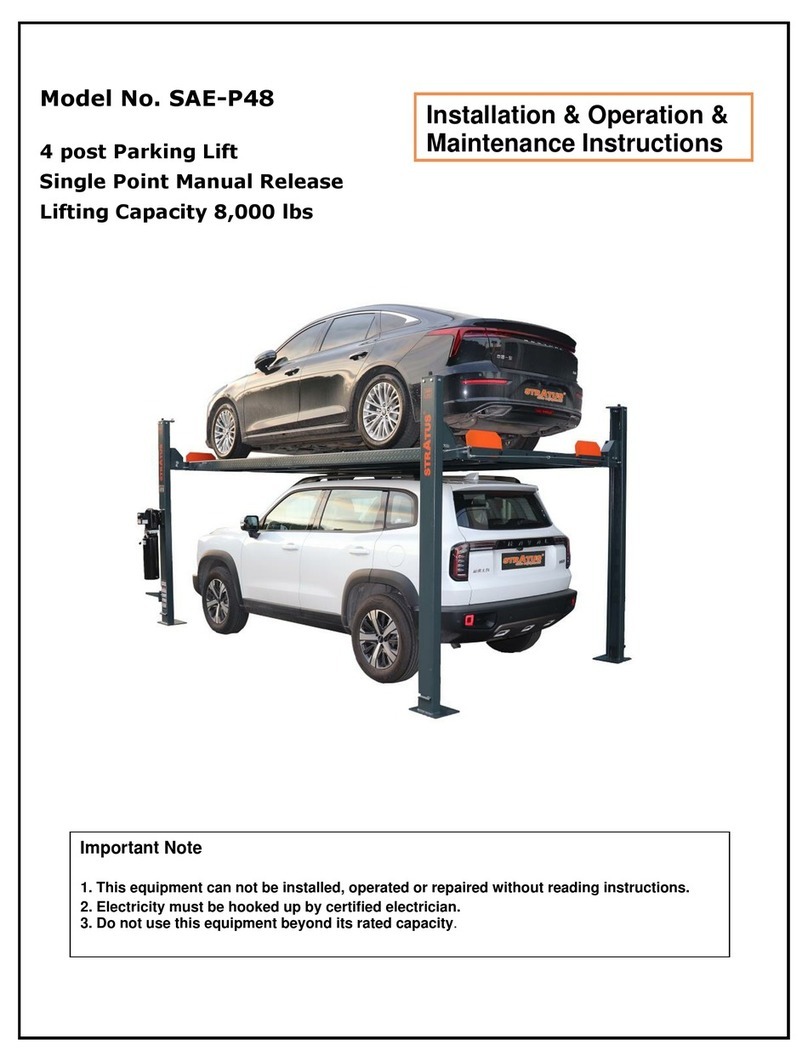
Stratus SAE-P166M Guide

Model No.:SAE-P166M
●Single Posng Li
●Single (1) Point Manual Release
●Liing Capacity:6600LBS
Installaon & Operaon
Maintenance & Instrucons
Single Post Parking Li Installaon & Operaon & Maintenance Instrucons
Important Note
1.This equipment can not be installed, operated or repaired without reading instrucons.
2.Electricity must be hooked up by cered electrician.
3.Do not use this equipment beyond its rated capacity.

2
Table of contents
1-Table of content………………………………………………………………………………………………………3
1.1-Product Feature………………………………………………………………………………………………………3
1.2-Safety lock structure…………………………………………………………………………………………………3
2-Basic parameters of the equipment……………………………………………………………………………………4
2.1-Product Dimensions…………………………………………………………………………………………………4
2.2-Product structure……………………………………………………………………………………………………5
2.3-Tools required before installaon……………………………………………………………………………………5
3-installaon steps………………………………………………………………………………………………………6
3.1-Check the components of the li before installaon………………………………………………………………6
3.2-Check the standard parts in the accessories box, etc.………………………………………………………………6
3.3-Equipment installaon space………………………………………………………………………………………8
3.4-Foundaon preparaon for installaon……………………………………………………………………………8
3.5-Chassis and foot angle iron installaon……………………………………………………………………………8
3.6-Expansion screw installaon………………………………………………………………………………………8
3.7-Post Mount…………………………………………………………………………………………………………9
3.8-Yoke Mounng………………………………………………………………………………………………………9
3.9-Plaorm yoke installaon…………………………………………………………………………………………10
3.10-plaorm installaon………………………………………………………………………………………………11
3.11-Dust tray installaon………………………………………………………………………………………………12
3.12-fender installaon…………………………………………………………………………………………………12
3.13-Power unit installaon……………………………………………………………………………………………13
3.14-Limit switch and tubing installaon………………………………………………………………………………13
3.15-Power unit descripon……………………………………………………………………………………………14
4-Check aer installaon………………………………………………………………………………………………15
4.1-Notes on operaon…………………………………………………………………………………………………15
4.2-Operaon steps……………………………………………………………………………………………………15
5-Equipment maintenance and inspecon……………………………………………………………………………16
6-Troubleshoong………………………………………………………………………………………………………17

3
1-The main performance of equipment
The product is a hydraulic li .The product is manually unlocked, easy to operate, suitable for parking of various mod-
els below 6600LBS.
1.1-Product Features
When the hydraulic li is powered on through the power unit, press the buon switch, the gear pump works, the hy-
draulic oil pushes the piston rod up, and is brought up by the chain to the pulley and the liing arm, so as to achieve the
purpose of liing; In the process of liing the machine, the block and the safety lock tooth will blink and bite together
during each ascent process, so as to ensure that the hydraulic system will not cause slippage;
1.2-Safety lock structure (as shown in the picture)
Every me you use the li, you must check whether the safety lock is normal through the observaon hole of the col-
umn;
Method: Press the buon switch when there is no load, the plaorm rises to check whether it is engaged; press the low-
ering lever to check whether the safety lock is lowered to the lock posion; repeat the operaon several mes before
the vehicle can be lied;
Serial number Name Specicaon Quanty Remark
1Post observaon hole 1
2Safety Lock Assembly 1
3Return spring 1

4
2-Basic parameters of the equipment
Liing capacity 6600LBS/3000KG Motor voltage 220V
Max liing height 78 3/4″/2000mm Power 2.2Kw
Min height 4 15/16″/215mm Frequency 60Hz
Plaorm length 152″/3860mm Breaker 30A
Plaorm width 24″/609mm Hydraulic oil AW46/AW32
Plaorm space 34 5/8″/880mm Shipping Size 155″×30″×38″
3920×740×960mm
Liing me About 60s Shipping Weight 2753LBS/1250Kg
Lowering me About 50s
2.1-Product dimensions (as shown in the gure)

5
2.2-The structural group of the product (as shown in the gure)
2.3-The tools required before installaon are as follows:
Rotary hammer drill(Φ19)
English spanner(12")
carpenter's chalk
Pliers
Hammer
Ratchet spanner with socket(28#)
Screw Sets
Socket head wrench(3#,5#,8#)
Level bar
Lock wrench
Tap measure
Wrench set
(10#,13#,14#,15#,17#,19,24#,27#,30#)
Ser Name Qty Ps Ser Name Qty Ps
1Post welding 1created by self 9Plaorm Support Le Arm Welding 1created by self
2Upper cover 1created by self 10 Plaorm Support Right Arm Welding 1created by self
3limit switch 1Purchased parts 11 connecng yoke 1created by self
4power unit 1Purchased parts 12 fender 4created by self
5Foot angle iron 1created by self 13 car slats 4created by self
6Chassis welding 1created by self 14 Dust tray1 1created by self
7Approach board 2created by self 15 Dust tray2 1created by self
8Plaorm welding 2created by self 16 Dust tray 6created by self

6
3- Installaon steps
3.1- Please check the parts of the li before installaon (as shown in the picture)
3.2- Check the standard parts, etc. in the accessory box (as shown in the table below)
Sec. Name Photo Specicaon Qty PS
1Outer hex bolt with elasc at washer and
hex nut M16×50 14
2Expansion screw M19×160 12 3/4″
3Outer hex bolt with elasc at washer and
hex nut M20×100 8半扣
4Outer hexagon bolt with elasc at washer
M20×60 8
5Outer hex bolt with elasc at washer and
hex nut M20×80 8
6Socket head cap screws M16×45 4
7Phillips buon head screw with spring at
washer and hexagon nut M6×20 32

7
Sec. Name Photo Specicaon Qty PS
8Hexagon socket screw with elasc at
washer and hex nut M12×180 4half buckle
9Hexagon socket screw with elasc at
washer and hex nut M12×130 2half buckle
10 Hexagon socket screw with elasc at
washer and hex nut M12×80 2half buckle
11 fender cover 8
12 power unit backpack 1
13 Hexagon socket head screw with elasc
at washer M6×16 4
14 Outer hex bolt with elasc at washer
and hex nut M8×20 4
15 Limit switch (with wire)
1
16 hydraulic hose 1
17 Column plasc buckle cover
1
18 plasc gasket 15
19 plasc cable es 15
20 manual 1

8
Ser Name Spec Qty Ps
1Chassis welding 1created by self
2Foot angle iron 1created by self
3Hex bolts M16×50 6Standard Parts
4Flat pad φ16 6Standard Parts
5spring washer φ16 6Standard Parts
6Hex nuts M16 6Standard Parts
3.6-Expansion screw installaon (as shown in the picture)
Ser Name Spec Qty Ps
1Concrete oor 1
2Chassis and foot angle iron assembly created by self
3Expansion screw 3/4″12 Purchased parts
3.3-Equipment installaon space
According to the external dimension drawing of the product; the li must be at least 1 meter away from other xed
objects (such as the wall) to ensure that there is enough space to ensure that the vehicle can be driven on and o the
liing plaorm;
3.4 - Foundaon preparaon for installaon
Concrete type C20/25, the minimum thickness is 200mm, the strength is above 3000PSI, the atness error is less than
0.5%, and the newly poured concrete needs to be cured for more than 20 days;
3.5- Chassis and foot angle iron installaon (as shown in the picture)

9
3.7- Column installaon (as shown in the picture)
Ser Name Spec Qty Ps
1Column assembly 1created by self
2Hex bolts M20×60 8Standard Parts
3spring washer φ20 8Standard Parts
4Flat pad φ20 8Standard Parts
3.8 - Aachment yoke installaon (as shown in the picture)
Ser Name Spec Qty Ps
1Column assembly 1created by self
2Pulley assembly 1created by self
3Joining Yoke Welding 1created by self
4Flat pad φ20 8Standard Parts
5spring washer φ20 8Standard Parts
6Hex bolts M20×100mm 8Standard Parts

10
3.9-Plaorm yoke installaon (as shown in the picture)
Ser Name Spec Qty Ps
1Column assembly 1created by self
2Joining Yoke Welding 1created by self
3Plaorm support right fork arm welding 1created by self
4Plaorm support le fork arm welding 1created by self
5Hex nuts M20 8Standard Parts
6spring washer Φ20 8Standard Parts
7Flat pad Φ20 8Standard Parts
8Hex bolts M20×80mm 8Standard Parts
9Hexagon socket head screw
(adjust plaorm support yoke) M16×45L 4Standard Parts

11
3.10-Plaorm installaon (as shown in the gure)
Ser Name Spec Qty Ps
1Purchased parts 2created by self
2Plaorm le fork arm welding 1created by self
3Plaorm right fork arm welding 1created by self
4Socket head cap screws M12×180 4Standard Parts
5Flat pad Φ12 8Standard Parts
6spring washer Φ12 8Standard Parts
7Hex nuts M12 8Standard Parts
8Socket head cap screws M12×130 2Standard Parts
9Socket head cap screws M12×80 2Standard Parts

12
3.11-Dust tray installaon (as shown in the gure)
Ser Name Spec Qty Ps
1Dust tray2 1created by self
2Dust tray1 1created by self
3Dust tray 6created by self
4Phillips buon
head screw M6×20mm 32 Standard Parts
5Flat pad φ632 Standard Parts
6Hex nuts M6 32 Standard Parts
7Approach board 2created by self
3.12-Installaon of car fender (as shown in the gure)
Note: The equipment adopts a separate bridge approach plate. When parking a vehicle on the plaorm, the vehicle bar-
rier must be inserted into the designated posion;
Ser Name Spec Qty Ps
1fender 4created by self
2car slats 4created by self
3Hex bolts M16×50mm 8Standard Parts
4fender cover 8created by self
5Flat pad φ16 8Standard Parts
6spring washer φ16 8Standard Parts
7Hex nuts M16 8Standard Parts

13
3.13-Power unit installaon (as shown in the gure)
Note: The power unit can be installed on both sides of the column, which can be selected according to the needs of
customers;
Ser Name Spec Qty Ps
1power unit 1Purchased parts
2power unit backpack 1created by self
3Flat pad φ64Standard Parts
4spring washer Φ6 4Standard Parts
5Socket head cap
screws M6×16 4Standard Parts
6Hex bolts M8×20 4Standard Parts
7Flat pad Φ8 4Standard Parts
8spring washer Φ8 4Standard Parts
9Hex nuts M8 4Standard Parts
3.14- Limit switch installaon and oil pipe installaon (as shown in the picture)
Ser Name Spec Qty Ps
1power unit 1Purchased parts
2hydraulic hose 1created by self
3power cable 1Purchased parts
4Connect the limit
switch plug 1Purchased parts
5limit switch 1Purchased parts
Note: Only fresh and clean hydraulic oil is allowed, and 46# hydraulic oil is recommended; do not ll the oil barrel com-
pletely for the rst refueling, the hydraulic oil volume can meet the liing plaorm to the highest level;
Suggeson: replace the hydraulic oil with new hydraulic oil 6 months aer the rst use, and then replace it once a year;

14
Funconal descripon of each part of the power unit
**Important Informaon**
Pressure Valve: Clockwise adjustment increases pressure to make the power unit to have more power, counterclock-
wise adjustment decreases pressure to make the power unit to have less power.
Hydraulic Oil ow valve: Clockwise adjustment to speed up, counterclockwise adjustment to slow down.
3.15-Descripon of each component of the power unit

15
4-Check aer installaon
1) Whether the expansion bolts are installed in place;
2) Whether the buon stops when the hand is released;
3) Whether the sensivity of the limit switch is valid;
4) Rise and fall without jier; no abnormal noise;
5) Check whether the xing bolts, nuts and circlips are loose;
6) There is no oil leakage at the oil pipe connecon;
7) Product warning sckers and nameplates are complete and clearly visible;
4.1-Notes on operaon
1) Check the connecon of the oil pipe to ensure that there is no oil leakage before starng operaon;
2) It cannot be used if there is a problem with the safety device;
3) Check whether the center of gravity of the lied vehicle is in the middle of the liing plaorm, if not, please ad-
just the center of gravity before liing;
4) During the liing process, the operator and other relevant personnel should stand in the safe area;
5) When the plaorm is lied to the required height and the operator leaves, the power should be turned o to
avoid misoperaon by other personnel;
6) Make sure that the safety lock is locked in place before working under the vehicle;
7) Make sure that there is no one under the car before liing and lowering;
4.2-Operaon steps
1) In order to avoid personal injury and property damage, only trained personnel are allowed to operate the li;
2) Park the lied vehicle on the two plaorms to ensure that the vehicle is parked in the correct posion, stable
and does not slip;
3) Aer pressing the buon to raise the liing plaorm slightly, check the stability of the vehicle on the plaorm
again;
4) When the plaorm is lied to the required height, press the lowering lever to lock the mechanical safety lock in
place and turn o the power; check the stability of the lied vehicle again;
5) Before descending, be sure to check around the lied vehicle to make sure there are no people and obstacles;
6) Turn on the power switch; press the buon switch, when the safety lock is out of the lock posion, pull the un-
locking rope to lower the liing plaorm;

16
5-Maintenance and inspecon of equipment
Ser Name Method Cycle
1Oil cylinder and oil
pipe joint Before using the li, check for oil leakage; every day
2control buon Check whether the buon is "press to run, hand o to stop";every day
3safety lock combina-
on
Check whether the security lock can be unlocked and locked simultane-
ously;every day
4limit switch Press the up buon, and when the limit switch is acvated, does the li
stop the upward movement; every day
5Slider running track No. 1 lithium base grease is used for lubricaon, and there is no obstruc-
on by foreign objects on the running track;
every three
months
6Chains and chain pins Lubricate with No. 1 lithium base grease. If there are cracks, they should
be replaced;
every three
months
7Expansion bolt Check the condion of the expansion bolts and the ground, if there is any
looseness, deal with it urgently;
every three
months
8overall Li the li several mes back and forth with rated load or no load, and
the li should run stably without any abnormal noise;
every three
months
9Hydraulic oi
Change the hydraulic oil 6 months aer rst use and then annually there-
aer. Check the cleanliness of the hydraulic oil. If the hydraulic oil turns
black or there are impuries in the oil barrel, replace the hydraulic oil
immediately;
Per year

17
6- Troubleshoong of common faults
Symptoms reason soluon
Unusual sound found
Are there any traces of fricon inside the
cylinder?
Add lubricang oil inside the cylin-
der
Is there any obstacle in the column to clear
The motor does not turn and does
not rise
Bad wire contact Check and connect the wiring
The motor is disconnected and burned replace the motor
Damaged limit switch Replace limit switch
Motor turns but doesn't rise
motor reverse Correct the wire connecon
Relief valve is loose or obstructed adjust or clean
Damaged gear pump Replace the gear pump
The oil sucon pipe is loose and falls o Tighten the sucon pipe
Sucon pipe lter clogged to clean
Slowly unload aer ascending
Check oil pipe for oil leakage replace oil pipe
Poor cylinder seal replace
Poor sealing of one-way valve clean or replace
Defecve relief valve clean or replace
Solenoid unloading valve defecve clean or replace
slow ascent
Oil lter clogged clean or replace
air mixed in oil pressure Supplementary hydraulic oil
Overow valve adjustment is not in place Adjustment
Hydraulic oil becomes hot (above 45°) replace
Cylinder seals worn replace
Down throle stuck with obstrucon clean or replace
slow down
Dirty hydraulic oil replace
Throle valve is stuck replace
There is an obstacle in the tubing clean or replace

18
Table of contents
Other Stratus Lifting System manuals
Stratus
Stratus SAE-C9P Guide
Stratus
Stratus SAE-C10C Guide
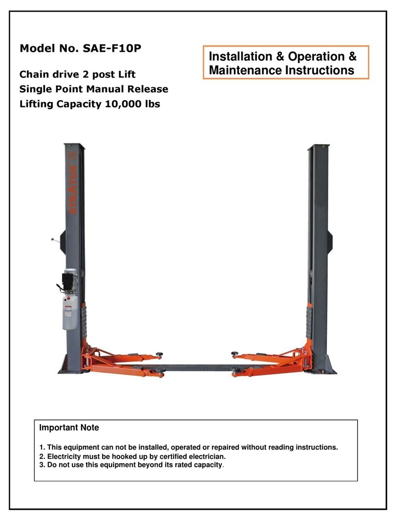
Stratus
Stratus SAE-F10P Guide
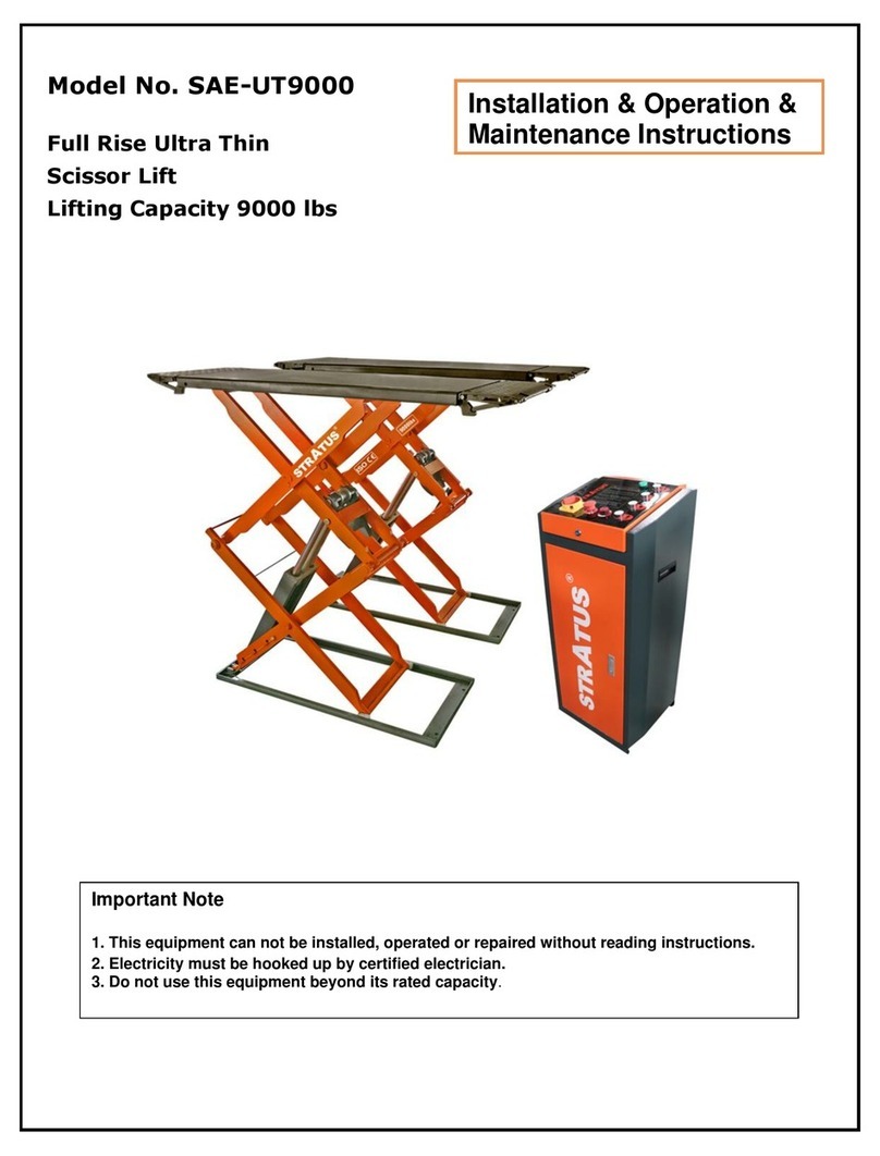
Stratus
Stratus SAE-UT9000 Guide

Stratus
Stratus SAE-C10P Guide
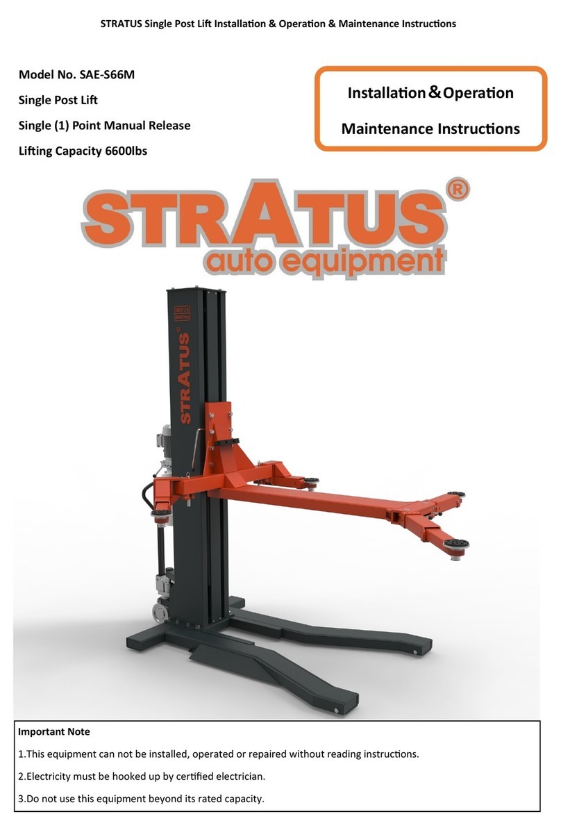
Stratus
Stratus SAE-S66M User manual
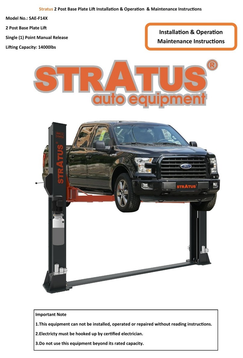
Stratus
Stratus SAE-F14X Guide
Stratus
Stratus MS9000XT User manual
Stratus
Stratus SAE-C14X Guide
Stratus
Stratus SAE-F12X Guide

