ERGOTEC UP & DOWN TURN 3 User manual
Montage- und Sicherheitshinweise für
deutsch
Stand 15.09.2022
Irrtum und technische Änderungen vorbehalten. Die aktuellste Version dieser Montage- und Sicherheitshinweise finden Sie auch auf www.ergotec.de
max. 100 kg
max. 120 kg
max. 140 kg
max. 100 kg
max. 120 kg
max. 100 kg
max. 100 kg
max. 120 kg
max. 140 kg
max. 100 kg
max. 120 kg
max. 100 kg
max. 120 kg
max. 140 kg
max. 160 kg
max. 120 kg
max. 140 kg
max. 120 kg
max. 120 kg
max. 140 kg
max. 160 kg
max. 120 kg
max. 140 kg
max. 120 kg
E-BIKE 25 km/h
E-BIKE 25 km/h
E-BIKE 25 km/h
E-BIKE 25 km/h
E-BIKE 25 km/h
E-BIKE 25 km/h
Sprunghöhe <_
60 cm
Sprunghöhe <_
60 cm
Sprunghöhe <_
60 cm
Sprunghöhe <_
120 cm
Sprunghöhe <_
120 cm
Sprunghöhe <_
180 cm
Sprunghöhe <_
60 cm
Sprunghöhe <_
60 cm
Sprunghöhe <_
60 cm
Sprunghöhe <_
120 cm
Sprunghöhe <_
120 cm
Sprunghöhe <_
180 cm
Mountain-Bike Safety Level
Road-/Gravel-/Travel-Bike Safety Level
City-/Trekking-Bike Safety Level
Cargo-Bike Safety Level
Jugendrad Safety Level
Kinderrad Safety Level
max. 100 kg
max. 100 kg
max. 140 kg
max. 100 kg
max. 160 kg
max. 140 kg
max. 160 kg
max. 120 kg
max. 120 kg
max. 100 kg
max. 140 kg
max. 120 kg
max. 160 kg
max. 180 kg
max. 100 kg
max. 120 kg
max. 140 kg
max. 160 kg
max. 120 kg
max. 140 kg
max. 100 kg
max. 100 kg
max. 250 kg
max. 100 kg
max. 300 kg
max. 250 kg
max. 300 kg
max. 120 kg
max. 120 kg
max. 100 kg
max. 140 kg
max. 120 kg
max. 160 kg
max. 180 kg
max. 120 kg
max. 140 kg
max. 160 kg
max. 180 kg
max. 140 kg
max. 160 kg
E-BIKE 25 km/h
E-BIKE 25 km/h
E-BIKE 25 km/h + 45 km/h
E-BIKE 25 km/h + 45 km/h
E-BIKE 25 km/h
E-BIKE 25 km/h
E-BIKE 25 km/h
E-BIKE 25 km/h
E-BIKE 45 km/h*
E-BIKE 45 km/h*
einspurig / mehrspurig
12“-24“
einspurig / mehrspurig
einspurig / mehrspurig
einspurig / mehrspurig
Lenksystem Sattelstütze
Die Produktklassifizierung der ergotec Safety Level entspricht der DIN EN ISO 4210 Norm für Fahrräder und
DIN EN 15194 für E-Bikes. E-Bike-Typ: Trittunterstützung bis angegebene Geschwindigkeit.
* Nachträglicher Einbau nur mit Abnahme einer anerkannten Prüfstelle und Eintragung in die Fahrzeugpapiere.
Vielen Dank, dass Sie sich beim Kauf Ihres neuen Vorbau-Adapters für ein Produkt
aus unserem Haus entschieden haben.
Vergleichen Sie das SAFETY LEVEL am Vorbau-Adapter mit der
beigefügten Tabelle und vergewissern Sie sich, ob dieser für den
vorgesehenen Einsatzzweck geeignet ist.
Vergewissern Sie sich vor der Montage des Vorbau-Adapters, dass
dieser für das maximal zugelassene Gesamtgewicht des Fahrrades
geeignet ist. Entsprechende Angaben dazu finden Sie auf der
Produktbeschreibung oder erhalten Sie bei Ihrem Fahrradhändler.
Lesen Sie vor Gebrauch die nachfolgenden Montage- und
Sicherheitshinweise aufmerksam durch. Bewahren Sie die Hinweise
sorgfältig auf und geben Sie diese ggf. an den Nachbesitzer weiter.
Montage
Die Montage setzt eine entsprechende Grundkenntnis voraus. Sollten Sie über
diese nicht verfügen, so wenden Sie sich bitte an den Fahrrad-Fachhandel.
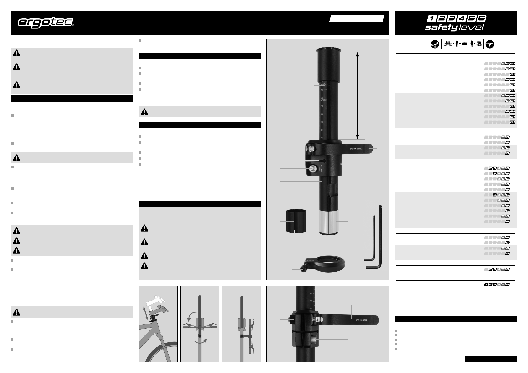
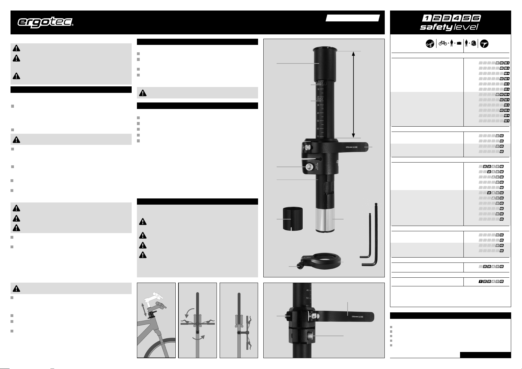
Überprüfen Sie, ob der Innendurchmesser cder Ahead-Klemmung des
Vorbau-Adapters (28,6 mm) mit dem Außendurchmesser des Gabelschafts
übereinstimmt.
Es gibt hier 2 unterschiedliche Größen:
bei 1“ Gabelschaft: Außendurchmesser 25,4 mm und
bei 1 1/8“ Gabelschaft: Außendurchmesser 28,6 mm.
Überprüfen Sie auch die Länge des Gabelschafts, welcher mindestens 155 mm
lang sein muss.
Bei einer Gabelschaftlänge kleiner als 155 mm kann der
Vorbau-Adapter nicht verwendet werden.
Überprüfen Sie ebenfalls, ob sich die Führungshülse d(25,2 mm) in den
Gabelschaft einschieben lässt. Sollte der Innendurchmesser des Gabelschafts
kleiner sein, so ziehen Sie die Führungshülse ab und schieben dann die
dünnere Führungshülse e(24,2 mm), welche im Lieferumfang enthalten
ist, auf das Gleitrohr des Vorbau-Adapters auf.
Die Innenseite des Gabelschafts sollte vor der Montage unbedingt mit einem
wasserresistenten Fett behandelt werden, da sonst Korrosion ein späteres
Verstellen erschwert.
Schieben Sie nun den Steuerlager-Einstellring fauf den Gabelschaft auf.
Achten Sie dabei darauf, dass sich die offene Seite an der Unterseite befindet.
Schieben Sie anschließend den Schaft des Vorbau-Adapters erst in und dann
die Ahead-Klemmung auf den Gabelschaft und richten diesen so aus dass sich
der Schnellspannhebel in Fahrtrichtung rechts befindet.
Kombinieren Sie den Vorbau-Adapter mit keinem Aluminium-
Gabelschaft – dies kann zu Funktionsstörungen führen.
Kombinieren Sie den Vorbau-Adapter mit keinem Carbon-
Gabelschaft – es besteht Bruchgefahr!
Der Gabelschaft darf aus Sicherheitsgründen maximal 2 mm
kürzer als die Außenklemmung des Vorbau-Adapters sein.
Ziehen Sie nun die Ahead-Klemmschraube gmit einem 5 mm Innen-
sechskant-Schlüssel und einem Anzugswert von 9 -10 Nm fest.
Überprüfen Sie anschließend, ob der Innendurchmesser der Ahead-Klemmung
des Vorbaus mit dem Außendurchmesser (28,6 mm) der Klemmhülse hdes
Vorbau-Adapters übereinstimmt.
Es gibt hier ebenfalls 2 unterschiedliche Größen:
bei 1“ Ahead-Vorbauklemmung: Innendurchmesser 25,4 mm und
bei 1 1/8“ Ahead-Vorbauklemmung: Innendurchmesser 28,6 mm.
Der Innendurchmesser der Ahead-Vorbauklemmung muss dem
Außendurchmesser der Klemmhülse des Vorbau-Adapters entsprechen.
Beachten Sie hierbei auch die Montage- und Sicherheitshinweise
des Steuerlager-Herstellers.
Schieben Sie nun die Ahead-Klemmung des Vorbaus auf die Vorbauklemmhülse
des Vorbau-Adapters. Bei einer Gabelschaftlänge von mehr als 175 mm muss
die Vorbauklemmhülse mit dem Vorbau an der Position MAX. 1 und bei einer
Gabelschaftlänge von 155-175 mm an Position MAX. 2 geklemmt werden.
Richten Sie anschließend den Vorbau so aus, dass dieser mit dem Vorderrad
in der Flucht steht.
Ziehen Sie nun die Schaftklemmschrauben am Vorbau mit dem von Ihrem
Vorbauhersteller vorgegebenen Anzugswert fest.
Sicherheitshinweis
Kontrollieren Sie den Anzugswert der Schrauben nach ca. 500 km und
anschließend regelmäßig im Rahmen der Service-Intervalle, mindestens
jedoch 1 x pro Jahr.
Befestigen Sie keine Zusatzanbauten wie Kindersitz oder Gepäckträger
am Vorbau. Dies könnte zu einer Überbeanspruchung und somit zum
Bruch des Vorbaus führen.
Dieser Vorbau-Adapter ist nicht für Mountainbiking oder Wettkämpfe
geeignet. Die hohen Beanspruchungen könnten zum Bruch des
Vorbau-Adapters führen.
Verstellen Sie die Höhe nicht während der Fahrt. Dies könnte zum
Sturz führen.
Um einen Sturz oder Unfall zu vermeiden, muss der Vorbau-Adapter
nach einer Beschädigung unbedingt ausgetauscht werden.
Vorbau-Adapter UP & DOWN TURN 3
Garantie
Für ergotec-Vorbau-Adapter gelten folgende Garantiezeiten:
mit Sicherheitslevel 6 6 Jahre oder 35.000 km
mit Sicherheitslevel 5 5 Jahre oder 30.000 km
mit Sicherheitslevel 4 4 Jahre oder 25.000 km
mit Sicherheitslevel 3 3 Jahre oder 20.000 km
mit Sicherheitslevel 2 3 Jahre oder 15.000 km
Eventuelle Garantieansprüche sollten über den
Fahrrad-Fachhandel abgewickelt werden. RICHTIGRADFAHREN.DE
Zum Einstellen des Steuerlagerspiels drehen Sie mit einem 3 mm Innen-
sechskant-Schlüssel die Einstellschraube iim Uhrzeigersinn, bis kein Spiel
oder Widerstand fühlbar ist.
Höhenverstellung
Um die Lenkeinheit in der Höhe zu verstellen, gehen Sie bitte wie folgt vor:
Öffnen Sie den Schnellspannhebel j.
Durch Hochziehen bzw. Herunterschieben des Vorbau-Adapters können Sie die
Höhe der Griffposition auf Ihre Bedürfnisse ausrichten.
Schließen Sie anschließend den Schnellspannhebel jwieder.
Überprüfen Sie dabei die Vorspannung des Schnellspannhebels. Sollte keine
Vorspannung mehr vorhanden sein, so drehen Sie die Einstellschraube k,
die sich auf der gegenüberliegenden Seite befindet, einige Umdrehungen im
Uhrzeigersinn.
Achten Sie dabei darauf, dass der Adapter nicht über die
Stop-Markierung herausgezogen wird.
Verdrehung
Um die Lenkeinheit zu verdrehen, gehen Sie bitte wie folgt vor:
Öffnen Sie den Schnellspannhebel j.
Ziehen Sie den Vorbau-Adapter über die Stop-Markierung bis zum Anschlag
nach oben.
Verdrehen Sie die Lenkeinheit um 90° nach rechts
Schieben Sie dann den Vorbau-Adapter wieder nach unten.
Schließen Sie anschließend den Schnellspannhebel jwieder.
k
g
j
c
g
e
i
h
j
d
f
MAX. 1
67 – 167 mm
MAX. 2
Assembly and safety instructions for
english
Valid: 15.09.2022
Error and technical changes reserved. The latest version of these installation and safety instructions can also be found at www.ergotec.de
max. 100 kg
max. 120 kg
max. 140 kg
max. 100 kg
max. 120 kg
max. 100 kg
max. 100 kg
max. 120 kg
max. 140 kg
max. 100 kg
max. 120 kg
max. 100 kg
max. 120 kg
max. 140 kg
max. 160 kg
max. 120 kg
max. 140 kg
max. 120 kg
max. 120 kg
max. 140 kg
max. 160 kg
max. 120 kg
max. 140 kg
max. 120 kg
E-BIKE 25 km/h
E-BIKE 25 km/h
E-BIKE 25 km/h
E-BIKE 25 km/h
E-BIKE 25 km/h
E-BIKE 25 km/h
Jump height <_
60 cm
Jump height <_
60 cm
Jump height <_
60 cm
Jump height <_
120 cm
Jump height <_
120 cm
Jump height <_
180 cm
Jump height <_
60 cm
Jump height <_
60 cm
Jump height <_
60 cm
Jump height <_
120 cm
Jump height <_
120 cm
Jump height <_
180 cm
Mountain-Bike Safety Level
Road-/Gravel-/Travel-Bike Safety Level
City-/Trekking-Bike Safety Level
Cargo-Bike Safety Level
Young adult-Bike Safety Level
Child Bike Safety Level
max. 100 kg
max. 100 kg
max. 140 kg
max. 100 kg
max. 160 kg
max. 140 kg
max. 160 kg
max. 120 kg
max. 120 kg
max. 100 kg
max. 140 kg
max. 120 kg
max. 160 kg
max. 180 kg
max. 100 kg
max. 120 kg
max. 140 kg
max. 160 kg
max. 120 kg
max. 140 kg
max. 100 kg
max. 100 kg
max. 250 kg
max. 100 kg
max. 300 kg
max. 250 kg
max. 300 kg
max. 120 kg
max. 120 kg
max. 100 kg
max. 140 kg
max. 120 kg
max. 160 kg
max. 180 kg
max. 120 kg
max. 140 kg
max. 160 kg
max. 180 kg
max. 140 kg
max. 160 kg
E-BIKE 25 km/h
E-BIKE 25 km/h
E-BIKE 25 km/h + 45 km/h
E-BIKE 25 km/h + 45 km/h
E-BIKE 25 km/h
E-BIKE 25 km/h
E-BIKE 25 km/h
E-BIKE 25 km/h
E-BIKE 45 km/h*
E-BIKE 45 km/h*
Single track / Multi track
12“-24“
Single track / Multi track
Single track / Multi track
Single track / Multi track
Steering System Seatpost
The product classification of the ergotec Safety Level corresponds to the DIN EN ISO 4210 norm for bikes and
DIN EN 15194 for e-bikes. E-bike-type: pedal assist up to the indicated speed.
* Retrofitting only with the approval of a recognised certifying body and entry in the documents for the bike.
Thank you for deciding to buy your new stem adapter from our company.
Compare the SAFETY LEVEL on the stem adapter with the attached
table in order to check whether it is suitable for the intended use.
Before fitting the stem adapter please make sure that it is suitable
for the max. permitted weight of the bike. You will find the relevant
details on the packing card, or alternatively you can ask your
bicycle dealer.
Before use please read the following assembly and safety
instructions carefully. Keep them in a safe place and pass
them on to the next owner if necessary.
Assembly
Basic technical knowledge is required for the assembly of this product. If you do
not have this knowledge, please use the services of a specialist bicycle dealer.
Check that the internal diameter cof the Ahead clamp of the stem adapter
(28.6 mm) fits the external diameter of the steer tube.
There are 2 different sizes:
with 1“ steer tube: external diameter 25.4 mm and
with 1 1/8“ steer tube: external diameter 28.6 mm.
Next you check the length of the steer tube, which must be at least 155 mm.
The stem adapter cannot be used with a steer tube length
of less than 155 mm.
Also check whether guide sleeve d(25.2 mm) can be inserted into the steer
tube. If the inner diameter of the steer tube is smaller, remove the guide sleeve
and push the thinner guide sleeve e(24.2 mm), which is included in the
scope of delivery, onto the sliding tube of the stem adapter.
Before assembly the inside of the steer tube must always be treated with
water-resistant grease, because otherwise corrosion could make later
adjustment difficult.
Now push the setting ring ffor the steering bearings onto the steer tube.
Make sure that the open side is facing downwards.
Next you push the shaft of the stem adapter into the Ahead clamp and then
place the clamp on the steer tube, adjusting it so that the quick release lever
is facing to the right in the direction of travel.
You should never combine the stem adapter with an aluminium
steer tube – this could lead to malfunctions.
For safety reasons the stem adapter should never be combined
with a carbon steer tube – risk of breakage.
For safety reasons the steer tube must not be more than 2 mm
shorter than the outer clamp of the stem adapter.
Now you tighten the Ahead clamping screw gwith a 5 mm hexagonal key
to a value of 9 -10 Nm.
Finally you check that the inner diameter of the Ahead clamp of the stem
matches the outer diameter (28.6 mm) of the clamp sleeve hof the stem
adapter.
There are also 2 different sizes here:
with 1“ stem clamp: inner diameter 25.4 mm and
with 1 1/8“ stem clamp: inner diameter 28.6 mm
The inner diameter of the Ahead stem clamp must fit the outer diameter of the
clamp sleeve of the stem adapter.
Please also observe the mounting and safety instructions of the
manufacturer of the steering bearings.
Now push the Ahead clamp of the stem on the stem clamping sleeve
of the stem adapter. If the steer tube is longer than 175 mm the stem clamping
sleeve has to be clamped on the stem in position MAX. 1, and with a steer
tube length of 155 - 175 mm it must be in position MAX. 2.
Next you adjust the stem in such a way that is aligned with the front wheel.
Now tighten the shaft clamping screws on the stem to the tightness value
specified by the stem manufacturer.
In order to adjust the play on the bearings you use an 3 mm hexagonal key
to turn the setting screw iin a clockwise direction until no more play or
resistance can be felt.
Stem adapter UP & DOWN TURN 3
Guarantee
For ergotec stem adapters the following guarantee periods apply:
with safety level 6 6 years or 35,000 km
with safety level 5 5 years or 30,000 km
with safety level 4 4 years or 25,000 km
with safety level 3 3 years or 20,000 km
with safety level 2 3 years or 15,000 km
Guarantee claims should be processed through
a specialist bicycle dealer. CYCLINGRIGHT.COM
Height adjustment
In order to adjust the height of the steering unit you proceed as follows:
Release quick release lever j.
By pulling the stem adapter upwards or pushing it downwards you can adjust
the height of the grip position to your individual requirements.
Next you close quick release lever jonce more.
In doing so you should check the pre-tension of the quick release lever. If there
is no longer any pre-tension you should turn adjusting screw k, which is
positioned on the opposite side, a number of rotations in a clockwise direction.
Make sure that the adapter is not drawn out
above the Stop mark.
Rotation
In order to rotate the steering unit you proceed as follows:
Release quick release lever j.
Pull the stem adapter upwards past the Stop mark to as far as it will go.
Rotate the steering unit by 90° to the right.
Push the stem adapter downwards again.
Next you close quick release lever jonce more.
Safety instructions
The tightness of the bolts must be checked after approx. 500 km and once more
during the regular service intervals (with once a year as a minimum).
You should not attach any additional equipment such as a child‘s seat
or a luggage rack to the stem. This could lead to excessive strain and
as a result to the breaking of the stem.
This stem adapter is not suitable for mountain biking or competitions.
The heavy demands could lead to breakage.
The height should not be adjusted during the ride. This could lead to
an accident.
To prevent the risk of a fall or accident, the stem adapter must always
be replaced if it has been damaged.
k
g
j
c
g
e
i
h
j
d
f
MAX. 1
67 – 167 mm
MAX. 2
Table of contents
Languages:
Other ERGOTEC Bicycle Accessories manuals

ERGOTEC
ERGOTEC AHS PREMIUM Supplement

ERGOTEC
ERGOTEC DOUBLE FLEX 3 Supplement

ERGOTEC
ERGOTEC Kobra Vario 40 Supplement

ERGOTEC
ERGOTEC Barracuda Supplement

ERGOTEC
ERGOTEC KOBRA VARIO Supplement

ERGOTEC
ERGOTEC SP-10.0 Supplement

ERGOTEC
ERGOTEC M-77LV Supplement

ERGOTEC
ERGOTEC UP & DOWN TURN 3 Supplement

ERGOTEC
ERGOTEC BUFFALO Supplement

ERGOTEC
ERGOTEC AHEAD Supplement

ERGOTEC
ERGOTEC Charisma Supplement

ERGOTEC
ERGOTEC UP & DOWN 3 Supplement

ERGOTEC
ERGOTEC PM-705N Supplement

ERGOTEC
ERGOTEC SEPIA XL Supplement

ERGOTEC
ERGOTEC FUTURA Supplement

ERGOTEC
ERGOTEC Stem Integra-BK User manual

ERGOTEC
ERGOTEC SP-9.0 Supplement

ERGOTEC
ERGOTEC Pedals EP-2 Supplement

ERGOTEC
ERGOTEC UP & DOWN RC Supplement


 product manual")


