manuals.online logo
Brands
  1. Home
  2. •
  3. Brands
  4. •
  5. Ergotron
  6. •
  7. Indoor Furnishing
  8. •
  9. Ergotron 48" Bench II User manual

Ergotron 48" Bench II User manual

01– 48”Wide Bench Shelf...................... Qty. 1........................... (see below)
28” Deep (ABS4829zz-xx and ABS4835zz-xx)
36” Deep (ABD4829zz-xx and ABD4835zz-xx)
02– Bench Leg Assemblies ................... Qty. 2
25” Bench Legs (ABS4829zz-xx and ABD4829zz-xx)
31” Bench Legs (ABS4835zz-xx and ABD4835zz-xx)
03– Bench Arm Left................................. Qty. 1
04– Cross Ends .......................................... Qty. 2
05– 1” Button-hd PB Screw................... Qty. 12
06– M6x12mm insert screw ................. Qty. 4
07– 2.5” End Caps ..................................... Qty. 4
08– Caster Inserts..................................... Qty. 4
09– Caster, 5” locking.............................. Qty. 4
10– M8x101mm button head screw. Qty. 8
11– Curved Washers................................ Qty. 8
12– Bench Base Tubes ............................ Qty. 2
28” Deep (ABS4829zz-xx and ABS4835zz-xx)
36” Deep (ABD4829zz-xx and ABD4835zz-xx)
Enclosed Parts List
13– 15” Bench Buttress........................... Qty. 2
14– 41.5” Bench Cross Tubes................ Qty. 2
15– Keps Nuts M6 .................................... Qty. 8
16– M6x12mm Pan screws ................... Qty. 8
17– Bench Arm Right.............................. Qty. 1
18– Support Screws ................................ Qty. 20
19– 48” Bench Pans.................................. Qty. 2
All Screw quantities listed here are the minimum needed for your
Bench assembly. There may be a few extra Screws included, which
are not counted in the Parts List.
To make the assembly of your Bench even easier, we have included the
required tools.. The handy Hex Driver Bit can be used in your electric
drill in place of the Hex Driver.
20- Tool, Hex Driver M4 ........................... Qty. 1
21- Tool, Hex Driver Bit 5/32”.................... Qty. 1
22- Tool, Hex Key 1/4”................................. Qty. 1
Tool, 3-Way Wrench(not shown).......... Qty. 1
These Assembly Instructions
are for the 48”Bench models.
Before beginning assembly
of your Bench, please take a
moment to review the parts
listed below to verify that your
shipment is complete.
04
06
07
03
02
09
05
08
01
10
13
11 14
12
15 16
17
18
19
48” Bench II
Your Bench is heavy!
Don’t try to lift it yourself. Work
with a buddy.
22
21
20
RI
UHY(ವ
www.ergotron.com | USA: 1-800-888-8458 | Europe: +31 (0)33-45 45 600 | China: 400-120-3051 | Japan: [email protected]
)RUWKHODWHVW8VHU,QVWDOODWLRQ*XLGHSOHDVHYLVLWZZZHUJRWURQFRP
M6 x 12mm Insert Screw
(small pink patch on end)
Glide Inserts placed
into the large holes
Leave these two holes open
M8 x 101mm button head screw Curved Washer
Left Leg Assembly
Right Leg Assembly
Side holes
Cross Tubes
M8 x 101mm button head screw Curved Washer
Leave these two holes open
Lower holes
48” Bench
Assembly Instructions
Step 3
Position the Right Leg Assembly (from Step 2) with two
Cross Tubes as shown. Insert one Bench Cap Screw
with a Curved Washer through a side hole, carefully
threading the Screw into the Cross Tube.
Repeat entire procedure for the remaining three
side holes.
Step 2
Orient one Bench Leg Assembly with one Base Tube
Assembly (from Step 1). The Glide Inserts should be
facing down.
Insert one Screw through one Curved Washer, then
carefully insert through one of the lower holes on the
Base Tube, threading into the Right Leg Assembly.
Repeat this procedure for the remaining three lower
holes on the Right and Left Leg Assembly.
Install Bench Casters by threading one into each Caster
Insert.
Left Leg
Assembly
Right Leg
Assembly
Thread one Caster
into each Caster
Insert AFTER theBase
Tubes have been
installed to the Legs.
NOTE: Loosen these
Support Screws (if
needed) to allow the
Base Tube to install
easier.
Glide Inserts
Step 1
Use a mallet to install the two Bench Caster Inserts into
each Bench Base Tube and secure with one Insert Screw
per Insert.
Use a mallet to pop two End Caps into the ends of both
Base Tubes.
RI
UHY(ವ
Step 4
Determine the desired height of your Shelf. This instruction
will place the shelf at the top of the legs, either 34” or
40” from the oor (depending on which height Bench you
purchased).
The holes along the Leg Assemblies are spaced at 1”
increments. Adjusting either one hole up or down will
modify the nal Shelf height by 1” respectively. Rotating the
Glides will also provide additional height adjustment.
NOTE: Your Shelf height can be adjusted at a later time if needed
by following Steps 5-8 below.
Step 5
Position the Left Bench Arm onto the Left Leg Assembly.
Align the top two openings of the Arm with Hole 2 of the
Leg Assembly. Loosely install a Support Screw through
the top two holes of the Arm into the Leg.
Install the remaining six Support Screws into the Left
Arm, but do not fully tighten any of the Support Screws.
Repeat entire procedure for the Right Bench Arm on the
Right Leg Assembly.
Step 6 (requires a 3-Way Wrench)
Position a Bench Pan between the Arms, aligning the
two tabs on each Arm with the two holes in the lower
corners of a Pan. Insert a Pan Screw through the Pan
and Arm Tab- capturing it with a Keps Nut (but do not
fully tighten). Repeat this procedure for the remaining
end of the Pan and for the second Pan.
Tighten all Pan and Support Screws.
NOTE: the 3-Way Wrench can be used to assist in tighten-
ing the Keps Nuts.
M6 x 12mm Pan Screw
Support Screw
34” or 40”
Leave top two
Holes open Hole 2
Left Leg Assembly
Right Leg Assembly
M6 Keps Nut
Arms
Second Pan shown installed
REMINDER: You may want to measure
your equipment to make sure it ts into
the selected Shelf location.
Left Bench Arm
RI
UHY(ವ
Step 7
Place the Bench Shelf (laminate facing down) onto the oor.
With the help of another person, carefully rotate the Base
Assembly (from Step 6) over onto the Shelf.
Position the holes on the Pans and Arms to align with the twelve pre-
drilled holes on the Shelf. Insert two 1”Button-hd PB Screws through
each center opening of the Bench Pans (shown circled at right).
Install the remaining PB Screws into each of the Arms and Pans. A total
of twelve PB Screws will be installed.
If a drawer and/or keyboard caddy are a part of this conguration,
install them now using their instructions.
With the help of a buddy, carefully rotate your Bench right
side up.
Pans
Arms
Rounded Edge of Shelf
Predrilled holes
Lower Metal Mounts
Cable Grommet
Workstation Screw
(not counted in Parts List)
Removal of Leg Covers and Cable Grommets
Remove the Leg Cover by: 1. First removing the top two
Workstation Screws. 2. Slightly lift the Cover upward and
o the lower metal mounts.
Cable Grommets are snapped into and out of each of the
circular Leg openings.
Step 8 (requires a 3-Way Wrench)
FIRST- from the rear of your Bench, align one Buttress
with one hole on the Back Pan. Install a Pan Screw
through the Buttress and loosely capture using a Keps
Nut on the opposite side.
SECOND- position one Cross End on the remaining
Buttress end and install a Pan Screw and Keps Nut in the
same manner, but do not fully tighten.
THIRD- rotate the Buttress to align the Cross End with
two openings on the Leg. Secure the Cross End to the
Leg using two Support Screws.
Repeat this entire procedure for the remaining Buttress
and Cross End on the opposite end.
Tighten all Pan Screws, Support Screws and Keps Nuts.
Congratulations! Your 48” Bench assembly is complete.
M6 x 12mm Pan Screw
1” button Hd PB Screw
M6 Keps Nut
Buttress
Back Pan hole
Support Screw
FIRST Install this Pan Screw
SECOND Install this Pan Screw
THIRD Install the Cross End
NOTE: The purpose of the Buttress is not to
support your Bench Shelf. It is intended to make
your Bench absolutely rigid under extreme
weight conditions.
RI
UHY(ವ
RI
UHY(ವ
k(UJRWURQ,QF$OOULJKWVUHVHUYHG
www.ergotron.com |
USA: 1-800-888-8458
|
Europe: +31 (0)33-45 45 600
|
China: 400-120-3051
|
Japan: [email protected]
)RUORFDOFXVWRPHUFDUHSKRQHQXPEHUVYLVLWKWWSFRQWDFWHUJRWURQFRP
)RU6HUYLFHYLVLWZZZHUJRWURQFRP
)RU:DUUDQW\YLVLWZZZHUJRWURQFRPZDUUDQW\

Other Ergotron Indoor Furnishing manuals
Ergotron Neo-Flex Notebook PC Stand User manual

Ergotron

Ergotron Neo-Flex Notebook PC Stand User manual

Ergotron WorkFit-C Dual User manual

Ergotron

Ergotron WorkFit-C Dual User manual

Ergotron WorkFit-A, Single LCD Mount, LD User manual

Ergotron

Ergotron WorkFit-A, Single LCD Mount, LD User manual

Ergotron Neo-Flex User manual

Ergotron

Ergotron Neo-Flex User manual

Ergotron Zido 2-drawer Enclosure User manual

Ergotron

Ergotron Zido 2-drawer Enclosure User manual

Ergotron Styleview Vertical Lift LCD Monitor Dimensions

Ergotron

Ergotron Styleview Vertical Lift LCD Monitor Dimensions

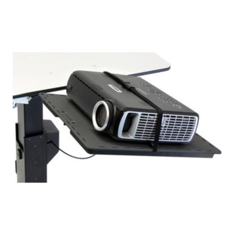
Ergotron Projector Shelf for TeachWell User manual

Ergotron

Ergotron Projector Shelf for TeachWell User manual

Ergotron SV10 User manual

Ergotron

Ergotron SV10 User manual

Ergotron WorkFit-A, Single LCD Mount, LD User manual

Ergotron

Ergotron WorkFit-A, Single LCD Mount, LD User manual

Ergotron JUV User manual

Ergotron

Ergotron JUV User manual

Ergotron WORKFIT Standing Desk Converter User manual

Ergotron

Ergotron WORKFIT Standing Desk Converter User manual

Ergotron Elevate II User manual

Ergotron

Ergotron Elevate II User manual

Ergotron WORKFIT-DL User manual

Ergotron

Ergotron WORKFIT-DL User manual

Ergotron Glide Upgrade User manual

Ergotron

Ergotron Glide Upgrade User manual

Ergotron Modesty Panel User manual

Ergotron

Ergotron Modesty Panel User manual

Ergotron Zido ZGBCG User manual

Ergotron

Ergotron Zido ZGBCG User manual

Ergotron Zido ZAH25CG/CG4 User manual

Ergotron

Ergotron Zido ZAH25CG/CG4 User manual

Ergotron Zido Handle User manual

Ergotron

Ergotron Zido Handle User manual

Ergotron 72” AnthroBench II User manual

Ergotron

Ergotron 72” AnthroBench II User manual

Ergotron 97-540-053 User manual

Ergotron

Ergotron 97-540-053 User manual
Ergotron ZAH25CG/CG4 User manual

Ergotron

Ergotron ZAH25CG/CG4 User manual

Ergotron 19610 User manual

Ergotron

Ergotron 19610 User manual

Ergotron LearnFit SE Troubleshooting guide

Ergotron

Ergotron LearnFit SE Troubleshooting guide

Ergotron WorkFit-D User manual

Ergotron

Ergotron WorkFit-D User manual

Popular Indoor Furnishing manuals by other brands

Invacare Softform Premier Active 2 user manual

Invacare

Invacare Softform Premier Active 2 user manual

Broyhill BL-TV-060-21A Assembly instructions

Broyhill

Broyhill BL-TV-060-21A Assembly instructions

KEUCO Stageline 32842 0000 Series Mounting instruction

KEUCO

KEUCO Stageline 32842 0000 Series Mounting instruction

DIR Paris instruction manual

DIR

DIR Paris instruction manual

Vivo DESK-V000VS instruction manual

Vivo

Vivo DESK-V000VS instruction manual

mFi URBAN LOFT BED Assembly instructions

mFi

mFi URBAN LOFT BED Assembly instructions

LivingXL 500LB Assembly and safety instructions

LivingXL

LivingXL 500LB Assembly and safety instructions

OVE EDENDERRY 30 installation manual

OVE

OVE EDENDERRY 30 installation manual

VECELO KHD-XF-CS01-GLD Assembly instructions

VECELO

VECELO KHD-XF-CS01-GLD Assembly instructions

WB Manufacturing FLIP TOP RECTANGLE TABLE Assembly instructions

WB Manufacturing

WB Manufacturing FLIP TOP RECTANGLE TABLE Assembly instructions

Baxton Studio Sorrento BBT8013 Assembly instructions

Baxton Studio

Baxton Studio Sorrento BBT8013 Assembly instructions

LINSY HOME LH618E3 manual

LINSY HOME

LINSY HOME LH618E3 manual

RH Baby&child PFEIFFER UPHOLSTERED BED FULL & QUEEN Assembly instructions

RH Baby&child

RH Baby&child PFEIFFER UPHOLSTERED BED FULL & QUEEN Assembly instructions

Cheyenne Products CPFB1983 Assembly instructions

Cheyenne Products

Cheyenne Products CPFB1983 Assembly instructions

Fox Manhattan 7510041 quick start guide

Fox

Fox Manhattan 7510041 quick start guide

Fursys Ringo S50 Series quick start guide

Fursys

Fursys Ringo S50 Series quick start guide

Monarch Specialties I 3055 Assembly instructions

Monarch Specialties

Monarch Specialties I 3055 Assembly instructions

RST Portofino OP-PECLBOTTO2B-PORVII Accessories assembly instructions

RST

RST Portofino OP-PECLBOTTO2B-PORVII Accessories assembly instructions

manuals.online logo
manuals.online logoBrands
  • About & Mission
  • Contact us
  • Privacy Policy
  • Terms and Conditions

Copyright 2025 Manuals.Online. All Rights Reserved.