EMPFÄNGER MINI 1 KANAL 433 Z1
Allgemein
Der Empfänger SEL 2641 R433 Z1 ist eine Komponente unseres Funksystems 433, um Automationen
und elektrische sowie elektronische Systeme fern zu steuern.
Dank der hochsicheren Codierung, „ “, können wir einen
manipulationssicheren Betrieb gewährleisten. Der vom Handsender gesendete Code ändert sich bei
jeder Aktivierung und der Mikrocontroller im Empfänger syncronisiert alle eingelesenen Sender im
System.Die Programmierung erfolgt selbstlernend durch 1 Taste.
Der Empfänger entspricht den europäischen Normen 89/336/CEE , 73/23/CEE, EN 60335-1,
EG Konformitätsbescheinigung.
®
KeeLoq Hopping code
Technische daten
Empfängertyp: ............................................................................Superheterodyne
Modulation: ...............................................................................AM/ASK
Frequenz: ...................................................................................433,92 MHz
Frequenz des lokalen Oszillators: .................................................6,6128 MHz
Zwischenfrequenz: ......................................................................10,7 MHz
Empfindlichkeit (für erfolgreiches Signal):....................................... -115 dB
Eingangsimpedanz: ....................................................................50 Ohm
Max. Speicher: ...........................................................................85 Handsendercodes
Spannungsversorgung: ................................................................12/24 VAC/DC
Ruhestrom: .................................................................................13/18 mA
Laststrom: ..................................................................................24/41 mA
Relaisanzahl: ..............................................................................1 (1 NO-NC), Leistung 24 VA
Betriebstemperatur .....................................................................-20 bis + 70 °C
Abmessung: ...............................................................................80x80x50 mm
Gewich.......................................................................................gr. 130
Positionierung
Die Positionierung des Empfängers ist für die
Empfangsleistung wichtig um eine gute Funktion zu
gewährleisten. Der Installationsort sollte nicht in
unmittelbarer Nähe von Störquellen ( z.B. EDV/Stromverteiler
mit hoher Leistung) sein.
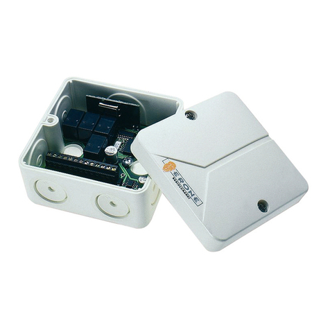
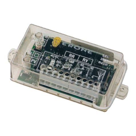
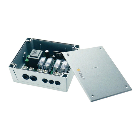
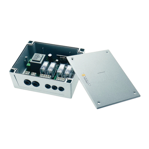
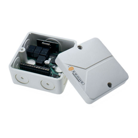
Der Empfänger bestehet aus: (Bild. 3)
!1 Gehaüse mit platine
!1 Deckel
!2 Schrauben
!2 Gummidichtung.
!1 Antenne
Empfänger
Montagen
Empfängerdeckel entfernen.
Das Gehäuse mit Schrauben befestingen. Am Ende die Gummidichtung befestigen.
Anschlüsse (Bild. 5)
Stromversorgung : Antenne:
Anschlüsse 11,12 : 12 VAC/DC Anschluß 15 : Schirm
Anschlüsse 11,13 : 24 VAC/DC Anschluß 14 : Antenne
Relaisanschlüsse:
Anschlüsse 8,9 : NO Relais Anschlüsse 9,10 : NC Relais
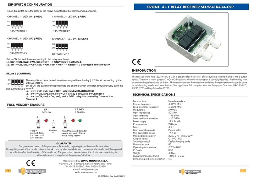
Einstellung des Relais K4 (Bild. 4)
Das Relais K4 Kann durch den Jumper JP1 als on /off oder impuls eingestellt werden
Speicherung
Der Empfänger speichert auf sequentielle Weise die Tasten eines Handsenders.
Zur Handsenderspeicherung drücken Sie am Empfänger die Taste P1 für etwa 2 Sekunden, bis die
grüne LED DL4 aufleuchtet. Taste P1 loslassen. Drücken Sie jetzt die Handsendertaste, die Sie
speichern möchten.Die grüne LED DL4 erlischt kurz und leuchtet neu auf, zur Bestätigung der erfolgten
Speicherung.
Wenn der Jumper JP1 in Position ON während der Handsenderspeicherung ist, blink die
grüne LED DL4 schnell, statt ein festes Licht.
Löschung einer Handsendertaste im Speicher
Drücken Sie für ca. 2 Sekunden die Taste P1,bis die grüne LED DL4 auf leuchtet.
Taste P1 loslassen.Drücken Sie die Taste des Handsenders, die Sie löschen möchten. Zwei Blinken der
grünen LED DL4 und roten LED DL3 hintereinander bestätigen die erfolgte Löschung der
Handsendertaste.
Speicher gesamt löschen
Drücken Sie die Taste P1 bis die grüne LED DL4 aufleuchtet, dann Taste P1 loslassen. Während die LED
leuchtet, drücken Sie die Taste P1 erneut, bis beide LED rot DL3 und grün DL4 dreimal aufleuchten.
Damit haben Sie den gesamten Speicher gelöscht.
Die Taste des betätigten Handsenders verursacht die Aktivierung des Relais K4. Nach der
Speicherung der Taste des Handsenders, die LED DL4 leuchtet noch 2 Sekunden auf. Während dieser
Zeit ist es möglich weitere Sender zu speichern, ohne die Taste P1nochmal zu drücken. Wenn DL4
erlischt, um andere Handsender zu speichern, ist es notwendig vom Anfang die Prozedur zu
wiederholen.
1 RELAY MINI RECEIVER 433 Z1
RICEVITORE MINI 1 RELE’ 433 Z1
Introduction
The receiver mod. SEL2641 R433-Z1 is designed for the control of automatic closing systems and anti-
®
burglar systems, thanks to its very high security coding system (KeeLoq Hopping code).
The code sent by the transmitter changes at every activation, avoiding any scanning and copying risk.
A special algorithm allows to keep synchronyzed transmitter and receiver.
The receiver has 1 output relay with NO and NO/NC contacts, and can be connected to many types of
mechanics as gates, garage doors, rolling shutters, awnings, anti-burglar appliances, lighting, etc.
The appliance can store into the EEPROM a serial number, a manufacturer key and the counter number of
more transmitters. The programming can be done in self-learning mode by means of one button.
The housing protection of IP65 allows external installations.
The appliance full complies with the European Directives 89/336/EEC, 73/23/EEC and Regulation EN
60950
Technical specifications
Receiver type . . . . . . . . . . . . . . . . . . . . . . . . . . . . . . . . . . . . . . . Superheterodyne
Carrier frequency . . . . . . . . . . . . . . . . . . . . . . . . . . . . . . . . . . . . 433,92 MHz
Local oscillator frequency . . . . . . . . . . . . . . . . . . . . . . . . . . . . . . 6.6128 MHz
Demodulation . . . . . . . . . . . . . . . . . . . . . . . . . . . . . . . . . . . . . . AM/ASK
Local Oscillator . . . . . . . . . . . . . . . . . . . . . . . . . . . . . . . . . . . . . VCO / PLL
Channel width . . . . . . . . . . . . . . . . . . . . . . . . . . . . . . . . . . . . . . > 25 KHz
Intermediate frequency . . . . . . . . . . . . . . . . . . . . . . . . . . . . . . . . 10.7 MHz
Input sensitivity . . . . . . . . . . . . . . . . . . . . . . . . . . . . . . . . . . . . . . -115 dBm
Local oscillator spurious emissions . . . . . . . . . . . . . . . . . . . . . . . . < -57 dBm
Input load:. . . . . . . . . . . . . . . . . . . . . . . . . . . . . . . . . . . . . . . . . 50 Ohm
Power supply: . . . . . . . . . . . . . . . . . . . . . . . . . . . . . . . . . . . . . . 12 / 24 Vac/dc
Consumption: Steady / 12 Vdc ( 2 relays excited) . . . . . . . 13 mA / 18 mA
Steady / 24 Vdc ( 2 relays excited) . . . . . . . 24 mA / 41 mA
Max applicable power . . . . . . . . . . . . . . . . . . . . . . . . . . . . . . . . 24VA
Relay number . . . . . . . . . . . . . . . . . . . . . . . . . . . . . . . . . . . . . . 1
Contacts . . . . . . . . . . . . . . . . . . . . . . . . . . . . . . . . . . . . . . . . . . NO, NO/NC
Memory capacity . . . . . . . . . . . . . . . . . . . . . . . . . . . . . . . . . . . . 85 user codes
TX security code . . . . . . . . . . . . . . . . . . . . . . . . . . . . . . . . . . . . . Rolling code
64
Max code combination number. . . . . . . . . . . . . . . . . . . . . . . . . . 2
Operating temperature. . . . . . . . . . . . . . . . . . . . . . . . . . . . . . . . -20°/+70°C
Housing protection. . . . . . . . . . . . . . . . . . . . . . . . . . . . . . . . . . . IP65
Weight . . . . . . . . . . . . . . . . . . . . . . . . . . . . . . . . . . . . . . . . . . . gr. 130
Overall dimensions (mm). . . . . . . . . . . . . . . . . . . . . . . . . . . . . . . 80 x 80 x 50
Positioning
The receiver allocation is very important for the best operation of the
system. Place the receiver far from interference sources as big
magnetic fields, informatic systems, radio emissions.
The installation and the antenna positioning is very important for the
best receiving as well.
Composition (Fig. 3)
!1 box with electronics
!1 cover
!2 screws
!2 gumm taps
!1 antenna net
!2 screws with plugs
I/O Contacts - (Fig. 5)
terminal 1 = Contact NO Relay terminal 11 = Input supply Common
terminal 2 = Contact C Relay terminal 12 = Input supply +12 Vac/dc
terminal 3 = Contact NO Relay terminal 13 = Input supply +24 Vac/dc
terminal 14 = Pole Antenna terminal 15 = GND Antenna
Fixing
Remove the receiver cover. Fix the box by using the screws and the plugs supplied;
At the end place the taps supplied over the holes to protect the screws head.
Transmitter memorization
The receiver makes the memorization of the transmitters buttons in sequential way.
Keep the button P1 pressed down until the red led DL4 switches on , release P1 and push the key which has
to be memorized.( key A or key B). The relay K4 excites for a while and the led DL4 switches off.
Relay K4 Configuration (Fig. 4)
The relay K4 can be configured in step mode. . Depending upon the position of the jumper JP1, the
relay will be in “Pulse mode” ( JP1 open) or “Step mode” (JP1 closed).
In step mode the relay excites at the first right transmission and releases at the next one.
Single transmitter cancelling
Keep the button P1 pressed down until the red led DL4 switches on ; release P1 and push the key “A” of the
transmitter to cancel : if this one was stored, it will be cancelled: at the end of the operation both the led DL3
and DL4 blink 2 times to confirm .
Complete memory reset
Keep the button P1 pressed down until the first red led DL4 switches on, release it, push it again and keep it
pushed down until 3 blinks of the leds DL3 and DL4 occur. In this way the memory is completely cancelled.
Memory Full
In case of full memory, that means 85 transmitters are already stored, if one try to store an extra transmitter, a
sequence of 3 blinks of DL3 and DL4 occurs and the operation fails.
Generalità
Il ricevitore mod. SEL2641 R433-Z1 è concepito per comandare automatismi di chiusura e sistemi d’allarme,
®
grazie ad una codifica ad altissima sicurezza (KeeLoq Hopping code). Il codice ricevuto dal trasmettitore cambia
ad ogni attivazione, evitando così il rischio della copia e successiva riproduzione. Un sistema interno permette di
mantenere sempre sincronizzati ricevitore e trasmettitore. Il ricevitore, dispone in uscita di relè con contatti puri NA
ed NA / NC e può essere collegato quindi ad un qualsiasi tipo di meccanismo ( cancello, porta di garage,
serrande, tapparelle, tende, centrale antifurto, illuminazione, ecc.). La programmazione in autoapprendimento si
effettua per mezzo di 1 tasto. La memorizzazione dei trasmettitori si effettua su EEPROM.Il contenitore IP65 ne
consente l’installazione in esterno.
L’apparecchiatura è costruita in conformità alle Direttive 89/336/CEE, 73/23/CEE ed alla Norma EN 60950.
CaratteristicheTecniche
Tipo ricevitore. . . . . . . . . . . . . . . . . . . . . . . . . . . . . . . . . . . . . . . Supereterodina
Frequenza portante . . . . . . . . . . . . . . . . . . . . . . . . . . . . . . . . . . . 433.92 MHz
Frequenza oscillatore locale . . . . . . . . . . . . . . . . . . . . . . . . . . . . 6.6128 MHz
Demodulazione . . . . . . . . . . . . . . . . . . . . . . . . . . . . . . . . . . . . . AM/ASK
Oscillatore locale . . . . . . . . . . . . . . . . . . . . . . . . . . . . . . . . . . . . VCO / PLL
Larghezza di canale . . . . . . . . . . . . . . . . . . . . . . . . . . . . . . . . . . > 25 KHz
Frequenza intermedia . . . . . . . . . . . . . . . . . . . . . . . . . . . . . . . . . 10.7 MHz
Sensibilità d'ingresso . . . . . . . . . . . . . . . . . . . . . . . . . . . . . . . . . . -115 dBm
Emissione dell'oscillatore locale . . . . . . . . . . . . . . . . . . . . . . . . . . < -57 dBm
Impedenza d’ingresso: . . . . . . . . . . . . . . . . . . . . . . . . . . . . . . . . 50 Ohm
Tensione di alimentazione . . . . . . . . . . . . . . . . . . . . . . . . . . . . . . 12 / 24 Vac/dc
Consumo: Vuoto / 12 Vdc ( relè attivato) . . . . . . . . . . . 13 mA / 18 mA
Vuoto / 24 Vdc ( relè attivato) . . . . . . . . . . . 24 mA / 41 mA
Potenza max applicabile . . . . . . . . . . . . . . . . . . . . . . . . . . . . . . . 24VA
N° Relè . . . . . . . . . . . . . . . . . . . . . . . . . . . . . . . . . . . . . . . . . . . 1
Contatti . . . . . . . . . . . . . . . . . . . . . . . . . . . . . . . . . . . . . . . . . . . NA, NA/NC
N° max codici utente . . . . . . . . . . . . . . . . . . . . . . . . . . . . . . . . . 85
Codice di sicurezza TX . . . . . . . . . . . . . . . . . . . . . . . . . . . . . . . . Rolling code
64
N° max combinazioni di codice . . . . . . . . . . . . . . . . . . . . . . . . . . 2
Temperatura di funzionamento. . . . . . . . . . . . . . . . . . . . . . . . . . . -20° ÷ +70°C
Grado di protezione . . . . . . . . . . . . . . . . . . . . . . . . . . . . . . . . . . IP65
Peso . . . . . . . . . . . . . . . . . . . . . . . . . . . . . . . . . . . . . . . . . . . . . gr. 130
Dimensioni (mm) . . . . . . . . . . . . . . . . . . . . . . . . . . . . . . . . . . . . 80 x 80 x 50
Posizionamento
La scelta della posizione del ricevitore è molto importante per
ottenere un buon funzionamento del sistema.posizionare il ricevitore
lontano da fonti di disturbo quali sistemi informatici, allarmi od altre
emissioni radio.
Composizione (Fig. 3)
!1 scatola con scheda ricevitore
!1 coperchio
!2 viti
!2 tappi di gomma
!1 filo d’antenna
!2 viti e 2 tasselli
Legenda Contatti (Fig. 5)
morsetto 8 = Contatto NA Relè morsetto 11 = Ingresso alimentazione Comune
morsetto 9 = Contatto C Relè morsetto 12 = Ingresso alimentazione +12 Vac/dc
morsetto 10 = Contatto NC Relè morsetto 13 = Ingresso alimentazione +24 Vac/dc
morsetto 14 = Antenna morsetto 15 = GND Antenna
Memorizzazione
Per memorizzare, premere e mantenere premuto il pulsante P1 per circa 2 secondi fino a che si accende il led
verde DL4 ( DL4 lampeggia se JP1 è in posizione ON ). Successivamente rilasciare il pulsante P1 e premere il
tasto del trasmettitore da memorizzare: DL4 si spegne e si riaccende per conferma dell’avvenuta memorizzazione.
In questo modo il tasto del trasmettitore attivato provocherà l’attivazione del relè K4. Al termine della
memorizzazione del singolo tasto del trasmettitore, il led DL4 rimane acceso ancora per 2 secondi. Durante
questo intervallo di tempo è possibile memorizzare ulteriori trasmettitori senza intervenire ancora sul pulsante P1.
Una volta spento però DL4, per memorizzare altri trasmettitori, è necessario ricominciare la procedura daccapo.
Fissaggio
Togliere il coperchio dal ricevitore. Fissare la scatola utilizzando viti e tasselli appropriati alla natura del
supporto. Al termine mettere i tappi di gomma in dotazione a protezione delle viti di fissaggio.
Configurazione relè K4 (Fig. 4)
Il relè K4 può essere configurato in modalità passo-passo. Per far ciò è sufficiente ponticellare JP1.
In modalità passo-passo il relè K4 si eccita al primo impulso ricevuto e si diseccita al successivo
Cancellazione parziale
Mantenere premuto P1 fino a quando si accende il led DL4. Rilasciare P1 e premere il tasto del trasmettitore da
cancellare. 2lampeggi consecutivi dei led DL4 e DL3, confermano l’avvenuta cancellazione.
Cancellazione totale
Mantenere premuto P1 fino a quando si accende il led DL4. Rilasciare P1 e ripremerlo immediatamente
tenendolo premuto fino a quando avvengono 3lampeggi consecutivi dei led DL4 e DL3, che confermano
l’avvenuta cancellazione totale della memoria.
Memoria piena
A memoria piena ( con 85 trasmettitori già memorizzati), se si cerca di memorizzarne uno nuovo, il ricevitore fa
lampeggiare 1 volta DL3 e DL4 contemporaneamente.


