ESAB Aristo U82 User manual

GB
Valid from program version 0.030460 896 074 GB 090515
Aristot
U82
Instruction manual

-- 2 --
TOCe
Rights reserved to alter specifications without notice.
1SAFETY 5...........................................................
2 INTRODUCTION 6...................................................
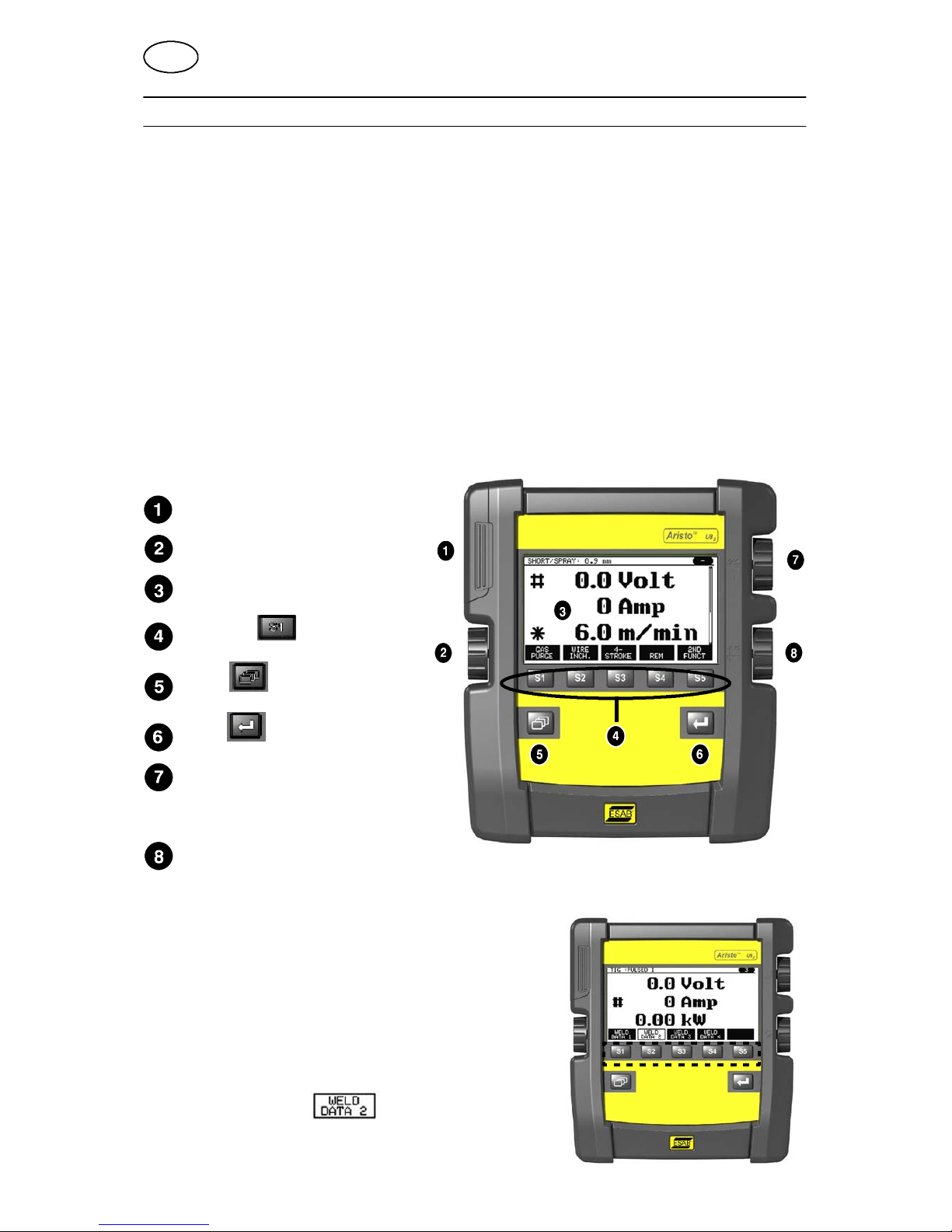
2.1 Control panel Aristo U82 6....................................................
2.1.1 Keys and knobs 6......................................................
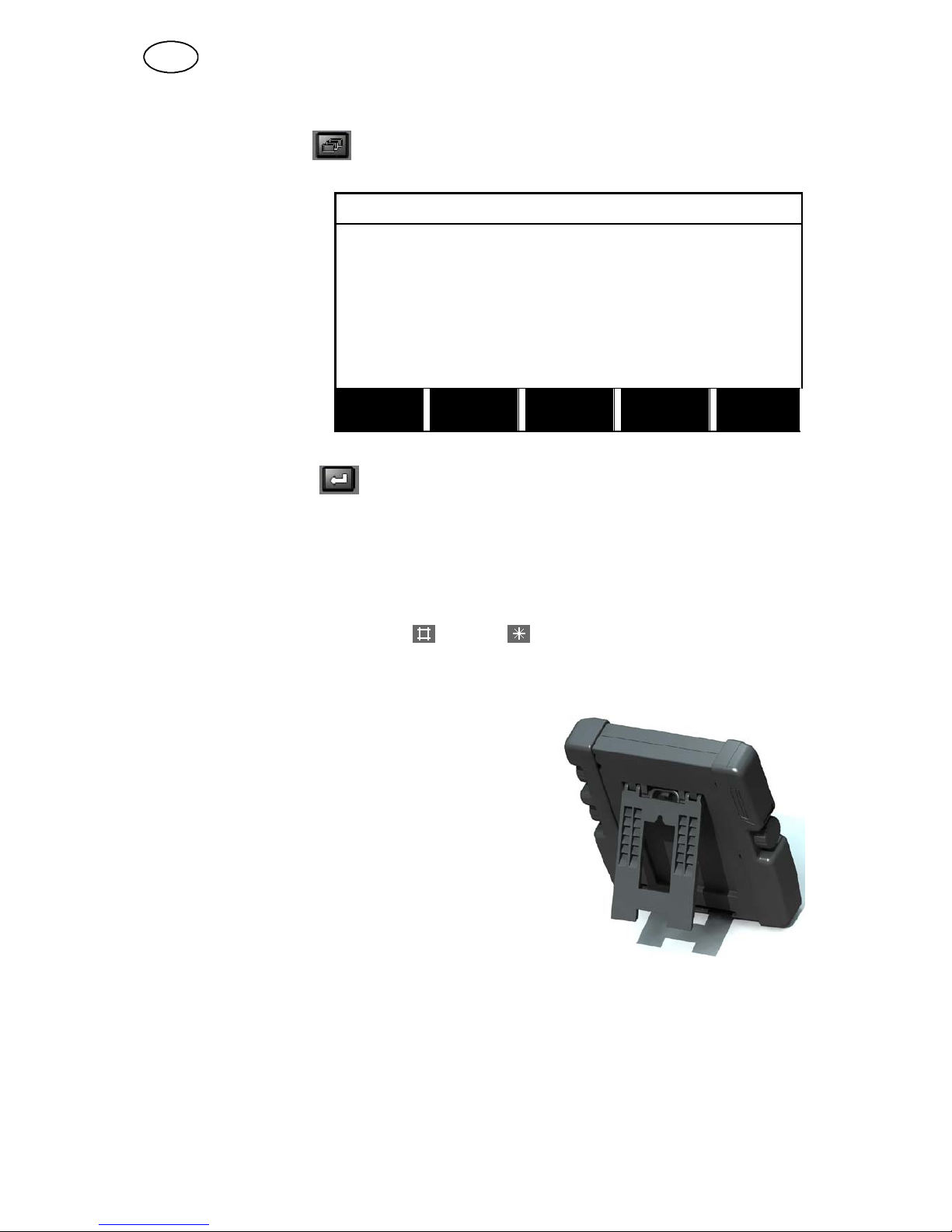
2.2 Location 7..................................................................
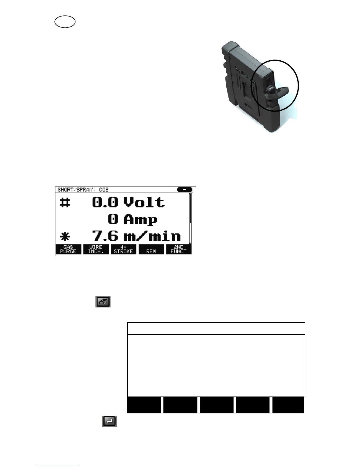
2.3 USB connection 7...........................................................
2.3.1 Insert USB memory 8...................................................
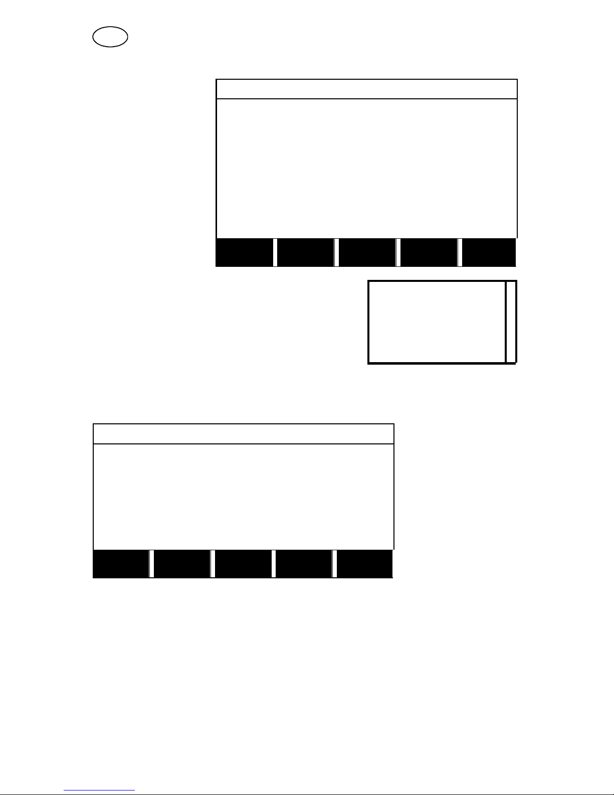
2.4 First step – choice of language 8..............................................
2.5 Display 9...................................................................
2.5.1 Symbols in the display 10.................................................
2.6 General information about settings 11...........................................
2.6.1 Setting of numerical values 11.............................................
2.6.2 Setting with given alternatives 11..........................................
2.6.3 Settings ON/OFF 11.....................................................
2.6.4 QUIT and ENTER 11.....................................................
3 MENUS 12...........................................................
3.1 Main menu 12...............................................................
3.1.1 Configuration menu 12...................................................
3.1.2 Tools menu 13..........................................................
3.1.3 Weld data setting menu 13................................................
3.1.4 Measure 14.............................................................
3.1.5 Weld data memory meny 14..............................................
3.1.6 Fast mode menu 15......................................................
4 MIG/MAG WELDING 15................................................
4.1 Settings in the weld data setting menu 16........................................
4.1.1 MIG/MAG welding with short--/sprayarc. 16.................................
4.1.2 MIG/MAG welding with pulsing 17.........................................
4.1.3 MIG/MAG welding with SuperPulseä, primary/secondary, short--/sprayarc/pulsing .
18
4.1.4 MIG/MAG welding with QSet 19...........................................
4.2 Function explanations for settings 19............................................
4.3 SuperPulse 24...............................................................
4.3.1 Wire and gas combinations 25.............................................
4.3.2 Different pulsing methods 25..............................................
4.3.3 Wire feed unit 25........................................................
4.4 QSet 27.....................................................................
5 MMA WELDING 27....................................................
5.1 MMA welding DC 27..........................................................
6 TIG WELDING 28.....................................................
6.1 Settings in the weld data setting menu 28........................................
6.1.1 TIG welding without pulsing DC 28.........................................
6.1.2 TIG welding with pulsing DC 29............................................
6.2 Function explanations for settings 29............................................
6.3 Other function explanations 32.................................................
7 ARC AIR GOUGING 33................................................
7.1 Settings in the weld data setting menu 33........................................
7.2 Function explanations 33......................................................

-- 3 --
TOCe
Rights reserved to alter specifications without notice.
8 MEMORY MANAGEMENT 34...........................................
8.1 Control panel working method 34...............................................
8.2 Store 34....................................................................
8.3 Recall 35....................................................................
8.4 Delete 37...................................................................
8.5 Copy 38.....................................................................
8.6 Edit 39......................................................................
8.7 Name 41....................................................................
9 CONFIGURATION MENU 42...........................................
9.1 Code lock 42...............................................................
9.1.1 Lock code status 43......................................................
9.1.2 Specify/edit lock code 43.................................................
9.2 Remote controls 44...........................................................
9.2.1 Forget override 44.......................................................
9.2.2 Configuration for digital remote control unit 44...............................
9.2.3 Configuration for analogue remote control unit 45............................
9.2.4 Scale on inputs 45.......................................................
9.3 MIG/MAG defaults 46.........................................................
9.3.1 Gun trigger mode (2--stroke/4--stroke) 46...................................
9.3.2 4--stroke configuration 47.................................................
9.3.3 Soft key configuration 48.................................................
9.3.4 Voltage measurement in pulsing 49........................................
9.3.5 AVC feeder 50..........................................................
9.3.6 Release pulse 50........................................................
9.4 MMA defaults 50.............................................................
9.5 Fast mode soft keys 50.......................................................
9.6 Double start sources 51.......................................................
9.7 Panel remote enable 51.......................................................
9.8 Auto save mode 51...........................................................
9.9 Trigger weld data switch 51....................................................
9.10 Multiple wire feeders 53.......................................................
9.11 Quality functions 54..........................................................
9.12 Maintenance 54..............................................................
9.13 Unit of length 55.............................................................
9.14 Measure value frequency 55...................................................
9.15 Register key 55..............................................................

-- 4 --
TOCe
Rights reserved to alter specifications without notice.
10 TOOLS 56............................................................
10.1 Error log 56..................................................................
10.1.1 Delete error message 57.................................................
10.1.2 Units 57................................................................
10.1.3 Error code descriptions 57................................................
10.2 Export/Import 60.............................................................
10.3 File manager 61..............................................................
10.3.1 Delete a file/folder 62.....................................................
10.3.2 Rename a file/folder 62...................................................
10.3.3 Create new folder 62.....................................................
10.3.4 Copy and paste files 63...................................................
10.4 Edit setting limits 64..........................................................
10.5 Edit measure limits 65........................................................
10.6 Production statistics 66.......................................................
10.7 Quality functions 67..........................................................
10.7.1 Store quality data 67.....................................................
10.8 User defined synergic data 68..................................................
10.8.1 Specify voltage/wire co--ordinates 68.......................................
10.8.2 Specify valid wire/gas combination 69......................................
10.8.3 Create your own wire/gas alternative 70....................................
10.9 Calendar 71.................................................................
10.10 User accounts 71............................................................
MENU STRUCTURE 72...................................................
WIRE AND GAS DIMENSIONS 78.........................................
ORDERING NUMBER 81.................................................
ACCESSORIES 82.......................................................

-- 5 --
bi23e
1SAFETY
NOTE! This unit is tested by ESAB in a general set--up. The repsonsibility for safety
and function, of the specific set--up, lies with the integrator.
Users of ESAB welding equipment have the ultimate responsibility for ensuring that anyone who
works on or near the equipment observes all the relevant safety precautions. Safety precautions
must meet the requirements that apply to this type of welding equipment. The following
recommendations should be observed in addition to the standard regulations that apply to the
workplace.
All work must be carried out by trained personnel well--acquainted with the operation of the welding
equipment. Incorrect operation of the equipment may lead to hazardous situations which can result
in injury to the operator and damage to the equipment.
1. Anyone who uses the welding equipment must be familiar with:
Sits operation
Slocation of emergency stops
Sits function
Srelevant safety precautions
Swelding
2. The operator must ensure that:
Sno unauthorized person is stationed within the working area of the equipment when it is
started up.
Sno--one is unprotected when the arc is struck
3. The workplace must:
Sbe suitable for the purpose
Sbe free from drafts
4. Personal safety equipment
SAlways wear recommended personal safety equipment, such as safety glasses, flame--proof
clothing, safety gloves.
SDo not wear loose--fitting items, such as scarves, bracelets, rings, etc., which could become
trapped or cause burns.
5. General precautions
SMake sure the return cable is connected securely.
SWork on high voltage equipment may only be carried out by a qualified electrician.
SAppropriate fire extinquishing equipment must be clearly marked and close at hand.
SLubrication and maintenance must not be carried out on the equipment during operation.
Do not dispose of electrical equipment together with normal waste!
In observance of European Directive 2002/96/EC on Waste Electrical and Electronic
Equipment and its implementation in accordance with national law, electrical equipment
that has reached the end of its life must be collected separately and returned to an
environmentally compatible recycling facility. As the owner of the equipment, you should
get information on approved collection systems from our local representative.
By applying this European Directive you will improve the environment and human
health!
GB

-- 6 --
bi23e
2 INTRODUCTION
To benefit as much as possible from your welding equipment, we recommend that
you read this instruction manual.
For general information about operation, see the instruction manuals for the power
source and the wire feed unit.
The text presented in the display is available in the following languages:
English, Swedish, Finnish, Norwegian, Danish, German, French, Italian, Dutch,
Spanish, Portuguese, Hungarian, Polish, American, Czech and Chinese.
2.1 Control panel Aristo U82
The control panel is supplied with a mounting bracket with screws and an English
instruction manual. A 1.2 m cable is mounted on to the panel. A USB memory and
an extension cable are available as accessories, see page 82.
Instruction manuals in other languages can be downloaded from the website,
www.esab.com.
Place for USB memory
Knob for moving cursor
Display
Soft keys
Menu
Enter
Knob for increasing or
decreasing set values and
setting the voltage, #
Knob for increasing or decreasing set values and setting the wire feed speed, *
2.1.1 Keys and knobs
Soft keys (4)
The five keys in a row under the display have
varying functions. These are “soft” keys, i.e.
they can have different functions depending on
which menu you are currently working in. The
current function for these keys can be seen
from the text in the bottom row of the display.
When the function is active, this is indicated by
the key turning white:
GB

-- 7 --
bi23e
Menu key (5)
Using the MENU key always takes you back to the main menu:
MIG/MAG
PROCESS MIG/MAG
METHOD SHORT/SPRAY
WIRE TYPE Fe
SHIELDING GAS Ar+8%CO2
WIRE DIAMETER 1.2 mm
CONFIGURATION"
TOOLS"
SET MEASURE MEMORY
FAST
MODE
Enter key (6)
Using the ENTER key confirms a selection.
Cursor knob (2)
Using the left--hand knob moves the cursor to different rows in the display.
Plus/minus knobs (7, 8)
The right--hand knobs increase or decrease the value of a setting. To the side of the
knobs there is a symbol, a square or a star . Most numerical settings can be
adjusted with either knob, although certain settings have to be made with a particular
knob.
2.2 Location
On the reverse of the control panel there is a
fold--out stand that enables you to put the panel
down and still view the display in an upright position.
The stand also acts as a mounting device, enabling
the control panel to be hung on the wire feed unit.
2.3 USB connection
External USB memories can be used to transfer programs
to and from the control panel. See more in chapter 10.2.
The files that are produced in the control panel are stored as xml files. The USB
memory must be formatted as FAT 32 in order to work.
During normal use there is no risk of “viruses” being able to infect the equipment. To
eliminate this risk entirely, we recommend that the memory that is used together with
this equipment not be used for any other purpose.
Certain USB memories may not work with this equipment. We recommend using
USB memories from a reputable supplier. ESAB assumes no responsibility for any
damage caused as a consequence of the incorrect use of a USB memory.
GB

-- 8 --
bi23e
2.3.1 Insert USB memory
Proceed as follows:
STurn off the power source’s main switch.
SOpen the cover on the left--hand end of the control
panel.
SInsert the USB memory in the USB connector.
SClose the cover.
STurn on the power source’s main switch.
2.4 First step – choice of language
This menu appears in the display the first time you start up the equipment.
The control panel is set to English on delivery. To select your language, proceed as
follows.
Press MENU to come to the main menu.
MIG/MAG
Using the left--hand
knob, position the
cursor on the CON-
FIGURATION row
PROCESS MIG/MAG
METHOD SHORT/SPRAY
WIRE TYPE Fe
SHIELDING GAS Ar+8%CO2
WIRE DIAMETER 1.2 mm
CONFIGURATION "
TOOLS"
SET MEASURE MEMORY
FAST
MODE
Press ENTER .
GB

-- 9 --
bi23e
CONFIGURATION
Position the cursor on
the LANGUAGE row.
Press ENTER to bring
upalistofthe
languages that are
available in the control
panel.
LANGUAGE ENGLISH
CODE LOCK"
REMOTE CONTROLS"
MIG/MAG DEFAULTS"
MMA DEFAULTS"
FAST MODE SOFT KEYS"
DOUBLE START SOURCES OFF
PANEL REMOTE ENABLE OFF
AUTO SAVE MODE OFF
TRIGGER WELDDATA SWITCH"
QUIT
Position the cursor on the row for your language and
press ENTER.
NORSK
POLSKI
PORTUGUES
SUOMI
SVENSKA
CHINESE
|
|
|
2.5 Display
MIG/MAG
PROCESS MIG/MAG
METHOD SHORT/SPRAY
WIRE TYPE Fe
SHIELDING GAS Ar+8%CO2
WIRE DIAMETER 1.2 mm
CONFIGURATION "
TOOLS"
SET MEASURE MEMORY
FAST
MODE
The cursor
The control panel’s cursor is presented as a shaded field around the text, with the
selected text turning white. The selection is displayed in the instruction manual with
bold text.
GB

-- 1 0 --
bi23e
Arrows and scroll bars
Where there is more information behind a row, this is indicated with a black arrow
behind the text. A scroll bar is presented to the right of the display if there are more
rows in the list:
Text boxes
At the bottom of the display are five boxes containing text that describes the current
function of the five keys directly below the boxes.
Energy saving mode
To increase the life of the background lighting, it is switched off after three minutes of
no activity.
2.5.1 Symbols in the display
AThe selected weld data set
BThe selected wire feed unit
CA fault has occurred. See chapter
15
DRecalled memory position number
ESelect the plus/minus knob marked
with # to increase or decrease a
parameter value.
FMeasured motor current
GSelect the plus/minus knob marked
with * to increase or decrease a
parameter value.
HEditing mode, editing memory
position
GB

-- 1 1 --
bi23e
2.6 General information about settings
There are three main types of setting:
SSetting of numerical values
SSetting with given alternatives
SSetting of ON/OFF mode
2.6.1 Setting of numerical values
When setting a numerical value, one of the two plus/minus knobs is used to increase
or decrease a given value. A number of values can also be altered from the remote
control unit.
2.6.2 Setting with given alternatives
Some settings are made by selecting an alternative from a list.
Such a list might look like this:
MIG/MAG
MMA
TIG
GOUGING
Here the cursor is placed on the row for MIG/MAG. By pressing ENTER in this
position, the MIG/MAG alternative is selected. If you want to choose another
alternative instead, position the cursor on the correct row by stepping up or down
with the left knob. Then press ENTER . If you want to exit the list without making a
selection, press QUIT.
2.6.3 Settings ON/OFF
For some functions, it is possible to set the values ON and OFF. The synergy
function during MIG/MAG and MMA welding is an example of such a function. The
ON or OFF settings can be selected from a list of alternatives as described above.
2.6.4 QUIT and ENTER
The “soft” key farthest to the right is used primarily for QUIT, although it is
occasionally used for other functions.
SPressing QUIT entails moving back to the previous menu or screen.
The key is called ENTER in this manual.
SPressing ENTER entails the execution of a selected choice in a menu or a list.
GB

-- 1 2 --
bi23e
3MENUS
The control panel uses several different menus. The menus are the Main,
Configuration, Tools, Weld data setting, Measure, Weld data memory and Fast mode
menus. The menu structures are displayed from the page 72.Duringstart--up,a
start--up screen containing information about the current program version is also
displayed briefly.
Start--up screen
3.1 Main menu
MIG/MAG
In the MAIN MENU,
you can change
welding process,
welding method, wire
type, etc.
From this menu you
can proceed to all other
sub--menus.
PROCESS MIG/MAG
METHOD SHORT/SPRAY
WIRE TYPE Fe
SHIELDING GAS Ar+8%CO2
WIRE DIAMETER 1.2 mm
CONFIGURATION "
TOOLS"
SET MEASURE MEMORY
FAST
MODE
3.1.1 Configuration menu
CONFIGURATION
In the CONFIGUR-
ATION menu you can
change language, alter
other basic settings,
unit of measurement,
etc.
LANGUAGE ENGLISH
CODE LOCK"
REMOTE CONTROLS"
MIG/MAG DEFAULTS"
MMA DEFAULTS"
FAST MODE SOFT KEYS"
DOUBLE START SOURCES OFF
PANEL REMOTE ENABLE OFF
AUTO SAVE MODE OFF
TRIGGER WELD DATA SWITCH"
QUIT
GB

-- 1 3 --
bi23e
3.1.2 Tools menu
TOOLS
In the TOOLS menu
you can transfer files,
view quality and
production statistics,
error logs, etc.
ERROR LOG"
EXPORT/IMPORT"
FILE MANAGER"
SETTING LIMIT EDITOR"
MEASURE LIMIT EDITOR"
PRODUCTION STATISTICS"
QUALITY FUNCTIONS"
USER DEFINED SYNERGIC DATA"
CALENDAR"
USER ACCOUNTS"
QUIT
3.1.3 Weld data setting menu
WELD DATA SETTING
In the WELD DATA
SETTING menu you
can alter various
welding parameters.
The menu has different
appearances depend-
ing on which welding
process is selected.
The example shows
MIG/MAG welding with
short--/sprayarc.
VOLTAGE 28.2 (+3.5) V
WIRE SPEED 6.0 M/MIN
INDUCTANCE 80%
SYNERGIC MODE ON
START DATA"
STOP DATA"
SETTING LIMITS"
MEASURE LIMITS"
SPOT WELDING"
EDIT DESCRIPTION"
CRATER
FILL
HOT
START
4--
STROKE QUIT
GB

-- 1 4 --
bi23e
3.1.4 Measure
SHORT/SPRAY. Fe, CO2, 1.2 mm
In MEASURE, you can
view measured values
for various welding
parameters while
welding is in progress.
# 0.0 Volt
0Amp
* 6.0 m/min
GAS
PURGE
WIRE
INCH
4--
STROKE REM
2ND
FUNCT
You can change the value of certain parameters in the Measure screen. Which
parameters these are depends on which welding process is set. The parameter
values that can be adjusted are always marked with #or *.
The measured values remain in the display even after welding has been completed.
You can move to different menus without losing the measurement values. If the set
value is altered when welding is not in progress, the measurement value is changed
to zero in order to avoid confusion.
TIP:
When pulsing, you can select whether the voltage value is to be displayed as an
average value or a peak value. This setting can be adjusted under MIG/MAG
defaults, see chapter 9.3.
3.1.5 Weld data memory meny
WELD DATA MEMORY
In the WELD DATA
MEMORY menu you
can store, recall, delete
and copy various set
weld data. The weld
data sets can be stored
in 255 different memory
positions.
1--
2--
3--
4--
5--
6--
7--
STORE
2ND
FUNCT QUIT
For further information, see the chapter 8“Memory management”.
GB

-- 1 5 --
bi23e
3.1.6 Fast mode menu
SHORT/SPRAY. Fe, CO2, 1.2 mm 7
In the FAST MODE
menu, you can “link”
soft keys to weld data
memory positions.
These settings are
carried out in the
Configuration menu.
The number of the
selected memory
position is displayed in
the top right corner.
# 28.5 Volt
0Amp
* 6.0 m/min
WELD
DATA 1
WELD
DATA 2
WELD
DATA 3
WELD
DATA 4
2ND
FUNCT
For further information, see the chapter 9.5 “Fast mode soft keys”.
4 MIG/MAG WELDING
Main menu →Process
MIG/MAG welding melts a continuously supplied filler wire, with the weld pool being
protected by shielding gas.
Pulsing is used to influence the transfer of the droplets from the arc so that it
remains stable and spatter--free, even with low weld data.
The table on page NO TAG shows the wire diameters that can be selected for
MIG/MAG welding with SHORT--/SPRAYARC.
The table on page NO TAG shows the wire diameters that can be selected for
MIG/MAG welding with PULSING.
When the MIG/MAG process is selected, you can choose between four methods by
selecting Method with the left--hand knob and then pressing ENTER. Choose
between short--/sprayarc, pulse, superpulse or QSet and then press ENTER again.
GB

-- 1 6 --
bi23e
4.1 Settings in the weld data setting menu
4.1.1 MIG/MAG welding with short--/sprayarc.
Settings Setting range In steps of Synergy
depend-
ent
Adjust-
able in
synergy
Voltage 8--60V 0.25 V
(displayed with
one decimal)
x x
Wire feed speed** 0.8 -- 25.0 m/min 0.1 m/min x
Inductance 0 -- 100% 1% x x
Regulator type 1--12 1 x --
Synergy* OFF or ON -- -- --
Gas pre--flow 0.1 -- 25 s 0.1 s x
Creep start OFF or ON -- x
“Hot start” OFF or ON -- x
“Hot start” time 0--10s 0.1 s x
“Hot start” wire feed Complete wire feed range 0.1 m/min x
“Touch sense” 0--20A
Crater filling OFF or ON -- x
Crater filling time 0--10s 0.1 s x
Final crater filling wire feed 1.5 m/min at current wire feed
speed
0.1 m/min x
Final crater filling voltage 8 -- 24.7 V x
“Release pulse”*** OFF or ON
Burnback time 0--1s 0.01 s x
Gas post--flow 0.1 -- 25 s 0.1 s x
Setting limits 1--50 -- -- --
Measure limits 1--50 -- -- --
Spot welding OFF or ON -- x
Spot welding time 0--25s 0.1 s x
*) The synergic line on delivery: solid wire (Fe), shielding gas CO2with wire 1.2 mm.
**)The setting range is dependent on the wire feed unit used.
***) Adjusted in the configuration menu MIG/MAG defaults.
GB

-- 1 7 --
bi23e
4.1.2 MIG/MAG welding with pulsing
Settings Setting range In steps of Synergy
depend-
ent
Adjust-
able in
synergy
Voltage 10 -- 50 V 0.25 V
(displayed with
one decimal)
x x
Wire feed speed* 0.8 -- 25.0 m/min 0.1 m/min x
Pulse current** 100 -- 650 A 4A x
Pulse time 1.7 -- 25.5 ms 0.1 ms x
Pulse frequency 16 -- 312 Hz 2Hz x
Background current 4 -- 300 A 1A x
Slope 1--9 1 x
Synergy*** OFF or ON -- -- --
Ka 0 -- 100% 1% x
Ki 0 -- 100% 1% x
Gas pre--flow 0.1 -- 25 s 0.1 s x
Creep start OFF or ON -- x
“Hot start” OFF or ON -- x
“Hot start” time 0--10s 0.1 s x
“Hot start” wire feed Complete wire feed range 0.1 m/min x
“Touch sense” 0--20A
Crater filling
(pulsed/not pulsed)
OFF or ON -- x
Crater filling time 0--10s 0.1 s x
Final crater filling wire feed 1.5 m/min at current wire feed
speed
0.1 m/min x
Final crater filling voltage 8 -- 33.2 V x
Final pulse current 100 -- max A x
Final background current 12 -- 50 A x
Final frequency 20 -- 270 Hz x
“Release pulse”**** OFF or ON
Burnback time 0--1s 0.01 s x
Gas post--flow 0.1 -- 25 s 0.1 s x
Setting limits 1--50 -- -- --
Measure limits 1--50 -- -- --
Spot welding OFF or ON -- x
Spot welding time 0--25s 0.1 s x
*) The setting range is dependent on the wire feed unit used.
**) Minimal background current and pulse current are dependent on which machine type is used.
***) The synergic line on delivery: solid wire (Fe), shielding gas CO2with wire 1.2 mm.
****) Adjusted in the configuration menu MIG/MAG defaults.
GB

-- 1 8 --
bi23e
4.1.3 MIG/MAG welding with SuperPulse™, primary/secondary,
short--/sprayarc/pulsing
Main menu →Process →Method →Phase →Method
Settings Setting range In steps of Synergy
dependent Adjustable
in synergy
Phase Primary or Secondary -- x
Method Short--/sprayarc or pulsing -- x
Voltage 10 -- 50 V 0,25 V(displayed
with 1 decimal)
x x
Wire feed speed* 0.8 -- 25.0 m/min 0.1 m/min x
Inductance 0 -- 100% 1% x x
Pulse current** 100 -- 650 A 4A x
Pulse time 1.7 -- 25.5 ms 0.1 ms x
Pulse frequency 16 -- 312 Hz 2Hz x
Background current 4 -- 300 A 1A x
Slope 1--9 1 x
Ka 0 -- 100% 1% x
Ki 0 -- 100% 1% x
Regulator type 1
Synergy*** OFF or ON -- -- --
Phase weld time 0--2.50s 0.01 s x
Gas pre--flow 0.1 -- 25 s 0.1 s x
Creep start OFF or ON -- x
“Hot start” OFF or ON -- x
“Hot start” time 0--10s 0.1 s x
“Hot start” wire feed Complete wire feed range 0.1 m/min x
“Hot start” voltage -- 1 4 -- + 2 7 V x--
“Touch sense” 0 -- 100 A x
Crater filling
(pulsed/not pulsed)
OFF or ON -- x
Crater filling time 0--10s 0.1 s x
Final crater filling wire feed 1.5 m/min at current wire feed
speed
0.1 m/min x
Final crater filling voltage 8 -- 33.2 V x
Final pulse current 100 -- max A x
Final background current 12 -- 50 A x
Final frequency 20 -- 270 Hz x
Cut--off pulse %
Burnback time 0--1s 0.01 s x
Gas post--flow 0.1 -- 25 s 0.1 s x
Setting limits 1--50 -- -- --
Measure limits 1--50 -- -- --
Spot welding OFF or ON -- x
Spot welding time 0--25s 0.1 s x
“Release pulse”**** OFF or ON x
*) The setting range is dependent on the wire feed unit used.
**) Minimal background current and pulse current are dependent on which machine type is used.
***) The synergic line on delivery: solid wire (Fe), shielding gas CO2with wire 1.2 mm.
****) Adjusted in the configuration menu MIG/MAG basic settings.
GB

-- 1 9 --
bi23e
4.1.4 MIG/MAG welding with QSet
Main menu →Process →Method
Settings Setting range In steps of
QSet -- 1 8 -- + 1 8 1
Wire feed speed* 0.8 -- 25.0 m/min 0.1 m/min
Inductance 0 -- 100% 1
Control type 1--12 1
Gas pre--flow 0.1 -- 25 s 0.1 s
Creep start OFF or ON --
Pinch off pulse 10 -- 120% 1%
Burnback time 0--1s 0.01 s
Gas post--flow 0.1 -- 25 s 0.1 s
Setting limits 1--50 --
Measure limits 1--50 --
Spot welding OFF or ON --
Spot welding time 0--25s 0.1 s
*) The setting range is dependent on the wire feed unit used.
4.2 Function explanations for settings
Voltage
Higher voltage increases the arc length and produces a hotter, wider weld pool.
The voltage setting differs between synergy and non synergy modes. In synergy
mode, the voltage is set as a positive or negative offset from the synergic line of the
voltage. In non synergy mode, the voltage value is set as an absolute value.
The voltage is set in the measure, weld data setting ,or fast mode menus. When the
remote control unit is used, the setting can be adjusted from here.
Wire feed speed
This sets the required feed speed of the filler wire in m/minute.
The wire feed speed is set in the measure, weld data setting ,or fast mode menus.
When the remote control unit is used, the setting can be adjusted from here.
Inductance
Higher inductance results in a wider weld pool and less spatter. Lower inductance
produces a harsher sound but a stable, concentrated arc.
Inductance is set in the weld data setting menu.
Only applies to MIG/MAG welding with short--/sprayarc.
Regulator type
Affects the short circuit process and heat in the weld.
The setting should not be altered.
GB

-- 2 0 --
bi23e
Pulse current
The higher of the two current values in the event of pulsed current.
Pulse current is set in the weld data setting menu with the synergy function switched
off.
Only applies to MIG/MAG welding with pulsing.
Pulse time
The time the pulse current is on during a pulse period.
Pulse current is set in the weld data setting menu with the synergy function switched
off.
Only applies to MIG/MAG welding with pulsing.
Pulse frequency
Time for background current which, along with the time for pulse current, gives the
pulse period.
Pulse frequency is set in the weld data setting menu with the synergy function
switched off.
Only applies to MIG/MAG welding with pulsing.
Background current
The lower of the two current values in the event of pulsed current.
Background current is set in the weld data setting menu with the synergy function
switched off. Only applies to MIG/MAG welding with pulsing.
Current
Pulse current
Background current Pulse
time
Pulse period time
Time
MIG/MAG welding with pulsing.
Slope
“Slope” means that the pulse current slowly increases/decreases to the set value.
The “Slope” parameter can be set in nine stages, with each stage corresponding to
100 μs.
The slope is important as regards the sound. A steep slope produces a louder and
sharper sound. Too gentle a slope can, in the worst case scenario, impair the pulse’s
ability to cut off the droplet.
GB
Other manuals for Aristo U82
4
Table of contents
Other ESAB Control Panel manuals

ESAB
ESAB Caddy A32 User manual

ESAB
ESAB A2 PEK User manual

ESAB
ESAB Caddy TA33 User manual

ESAB
ESAB 0558001912 Operating instructions

ESAB
ESAB 0558001913 Operating instructions

ESAB
ESAB A2 PEK User manual

ESAB
ESAB Aristo U82 User manual

ESAB
ESAB A2 Multitrac User manual

ESAB
ESAB T6 User manual

ESAB
ESAB Caddy A32 User manual