ESD DTS2 User manual

Electronic Systems Development
Airborne Data Acquisition And Telemetry System
DTS2
Rev 1.4
Note: reliminary documentation
lease report any errors.
Last changes 2009/01/04

NOTICE
© Copyright 2009
All Rights Reserved.
This documentation and related hardware and software developed by Electronic Systems
Development contains proprietary information protected by copyright. o part of this
document may be reproduced, stored in a retrieval system, or transmitted in any form by any
means electronic, mechanical, by photocopying, recording or otherwise without prior written
permission from Electronic Systems Development.
Information in this manual is subject to change without prior notice in order to improve
accuracy, design and function and does not represent a commitment on the part of the
manufacturer. Information furnished in this manual is believed to be accurate and reliable.
However, no responsibility is assumed for its use, nor for any infringements of patents or
other rights of third parties which may result from its use.
In no event will Electronic Systems Development or persons affiliated to Electronic Systems
Development be liable for direct, indirect, special, incidental or consequential damages
arising out of the use or inability to use the product or documentation, even if advised of the
possibility of such damages.
CREDITS
TITA is the property of RAP, CAR (Dr Mike Dixon).
IBM, IBM PC/XT/AT are all trademarks of International Business Machine Corporation.
Microsoft, Windows XP, DOS and MSDOS are all trademarks of Microsoft Corporation.
Other product names mentioned herein are used for identification purposes only and may be
trademarks and/or registered trademarks of their respective companies.
WARRANTY
The seller warrants that the equipment supplied will be free from defects in material and
workmanship for a period of 6 months from the confirmed date of purchase of the original
buyer.
NOTE:
This technical documentation is written with the assumption that the user of this equipment
either has good knowledge of electronics and computers including a basic knowledge of DOS
or has a person on their staff that has this knowledge.
Do not try to set up or work on this equipment if you are not suitably qualified to do so.
If this equipment is tampered with including drilling of mounting holes in the chassis
the warranty will be VOID.

Read this First !!
This is a Summery of Warnings found in this document.
If some of these warnings are not o served damage may result to the equipment or
data may e lost.
Connecting The System Power. Page 8.
Warning !! Do not connect more than 13.8 V DC to the
System power otherwise damage may result .
Connecting The Radio Antenna. Page 8.
Warning !! Make sure that the radio antenna is connected efore
switching power on, if the radio transmits without an antenna the radio will e damaged.
Connecting The GPS Antenna. Page 9.
Warning !! Make sure that the GPS antenna is connected efore
switching on power otherwise the GPS will e damaged.
NEVER connect or disconnect the GPS antenna while power is ON, Switch off first
then connect the antenna then switch power ack ON.
Connecting Analog Signals To The System. Page 9.
Warning !! Make sure that the analog voltages connected to the
system do not exceed +-10 Volts.
Connecting Parallel I/O To The System. Page 9
Warning !! Do not connect signals that exceed +-28 V to the counter and parallel
input channels, a minimum of 5 Volts is needed to switch the circuit.
Setting up the Radio. Page 11.
If required in your country you must apply for a radio frequency from your local FCC.
Warning !! Do not eject/insert the Compact Flash DISK cartridge while power is on.
First switch off power efore removing or inserting a Flash Disk otherwise the cartridge will
definitely e damaged, see page 14.

4
INDEX AGE
1 I TRODUCTIO 5
2. DESCRIPTIO 5
3. SYSTEM FEATURES 6
3.1 CO TROLLER
3.2 GPS
3.3 A ALOG TO DIGITAL
3.4 PARALLEL I/O
3.5 TELEMETRY
3.6 SYSTEM POWER REQUIREME TS
4. SOFTWARE 6
5. TELEMETRY PROTOCOL 7
5.1 TIMED PROTOCOL
6. SYSTEM LIMITATIO S 7
7. CO ECTIO S TO THE SYSTEM 8
7.1 CO ECTI G THE SYSTEM POWER
7.2 CO ECTI G THE RADIO A TE A
7.3 CO ECTI G THE GPS A TE A
7.4 CO ECTI G A ALOG I PUTS TO THE SYSTEM
7.5 CO ECTI G PARALLEL I/O TO THE SYSTEM
7.6 FLAGS
8. THE STATUS LED’S 11
9. STATUS PORT 11
10. DISPLAY 12
11. CO FIGURI G THE SYSTEM 12
12. DATA STORAGE 21
13. DATA FORMAT 22
14. ADC CHA EL OFFSET A D SLOPE VALUES 24
15. PERFORMA CE 26
16. I STALLI G THE SYSTEM 26
17. RECOMME DED COMPO E TS 27
18. APPE DIX 28

5
1. INTRODUCTION
The Data Acquisition and Telemetry System Version 2 (DTS2) has been developed to acquire
Analog, Digital and GPS data for recording and transmission via Radio Telemetry from an
Airborne system to a ground Base Station with the primary function of updating aircraft
position in the operations control room on the ground. The system has been designed and
customized to be 100% compatible with TITA .
2. DESCRI TION
The system is based on an imbedded 386 CPU module with PC compatible features such as,
RS232 COM ports and Compact Flash Disk support for data storage. The CPU module is the
main controller of the system and runs the Data Acquisition, Storage and Telemetry program.
DTS2 has an 8 channel 12 bit ADC chip, user defined counter channels, user defined I/O
ports, 6 Serial Channels ( RS232 ) and internal GPS and Radio Data Modem.
All address decoding Counter functions and Parallel I/O are implemented in a single
ALTERA FPGA chip which is configurable for a multitude of functions making the card
versatile and useable for many applications.
The CPU card runs a program which samples data from the ADC at user programmable rates,
reads the Parallel Input Ports and Flags, counts Events and ingests the GPS data, formats the
data to a Packet Data String (PDS) compatible with TITA , stores this string on Compact
FLASH Card at user programmable rates and transmits this string via Radio Telemetry to the
Ground Base Station for real-time aircraft tracking on the TITA display.
The system is user configurable for sample and update rates, Telemetry transmission rates and
disk storage rates, device ID and ADC offsets and slopes are also user programmable by
editing a straight forward TEXT configuration file.

6
3. System Features:
3.1 Controller:
Imbedded 386 CPU Controller Module with standard PC capabilities.
On card 4 Mb Dram.
2 serial Com ports ( RS232 ).
The operating system is Imbedded DOS.
3.2 G S:
ESD GPS1 Microblox 12 channel GPS module with external antenna.
Conforms to MEA data format.
Connects to one of the serial ports on the controller.
Position update of 1 per second.
3.3 ADC:
8 channel Analog to Digital converter with 12 bit resolution and protected bipolar inputs of
+- 5V or +- 10V (individually selectable).
Connects to analog sensors and instruments.
3.4 arallel I/O:
4 Protected Parallel input ports for monitoring flags and buttons.
2 Protected Counter channels for counting events such as flares fired.
4 Output ports with open collector drivers for switching on relays, LED’s etc.
3.5 Telemetry:
UHF or VHF with user selectable modulation ( FSK, GMSK and 4FSK ) baud rates up to
9600 Baud. Maximum 5 watt output power ( programmable ).
3.6 System ower requirements:
The system requires 12V @ 5 amps.
ote: a 24 V to 12 V converter is needed for 24 volt aircraft systems.
The 12VDC Power Connector is an C512 3 pin connector.
3.7 Enclosure Dimensions
Length =
16 cM , Width = 24.2 cM , Height = 6.1cM .
4. Software:
The 386 Module runs a program which acquires data from the GPS, Parallel Input,
Counter channels and the ADC channels.
These data are written to the Compact Flash Disk at a pre-selected rate, normally 1 record per
second.
The data are also formatted into the PDS ( Packet Data String ) for transmission via Telemetry
to the Ground Base Station. The Base Station receives the string, checks for and correct errors
and then sends the string to TITA which in turn displays the aircraft tracks on the TITA
display. The Packet Data String (PDS) is compatible with the TITA ESD_AC_I GEST
running on TITA .

7
An optional LabView ( DTS2_VIEW.exe ) utility is available for monitoring the data output
of the DTS2 on a graphical display. The LabView utility can be installed on a Laptop or
Tablet PC with Win XP ( not supplied by ESD ). The Laptop running the application
DTS2_VIEW must be connected to the DTS2 serial port P3.
5. Telemetry rotocol:
5.1 Timed protocol:
The Base Station listens only and the Airborne Systems synchronize their transmission
with the GPS time and pulse per second (PPS) interrupt.
Each Airborne System will have a numeric ID to determine when this system must transmit
its data. With this method the Base Station will receive an update on each second, if there are
3 aircraft then an update from a specific aircraft will be received every 3 seconds etc. If there
is only one Airborne System then an update can be received every second from that aircraft.
Experience has shown that an update every second produces too much data for TITA and
the airborne radio works hard. A suggested update in a single Airborne System setup is every
4 seconds. Data can be logged once per second on the Airborne System if so required.
6. System Limitations:
Radio reception is the most important factor effecting reliable updates from the Airborne
System. The placement of the Airborne Telemetry antenna is critical (should be on the
underside of the aircraft fuselage and as far as possible from the aircraft communications
antennas). The placement and height of the Base Station antenna is very important for good
reception.
The GPS module used in this system relies on good coverage of the sky to detect satellites.
Do not try to test the system in a metal roof hangar as the G S will not detect any satellites
and the Error light will stay lit.
No Analysis package is supplied with DTS2. The user must read the files stored on the CF
card with Microsoft Excel or a similar program that can read “comma delimited” text.
Microsoft Excel can be used to draw up graphs and summaries of the data from a flight.
TITA is used to display aircraft tracks and no provision is made for a separate output to
display aircraft position on a monitor.
DTS2 Panels
DTS2 Front anel
The Front Panel shows the 8 LED’s , the Power Breaker / Switch and the Compact Flash
socket / slot

8
DTS2 Back anel
ANALOG Channels
Serial I/O Radio Antenna G S Antenna
G S Data Output Digital I/O
7. Connections To The System
7.1 Connecting The System To ower
Both the Base and Airborne systems require 12 VDC.
Warning !! Do not connect more than 13.8 V DC to the system power otherwise damage
will result .
Base Station.
The Base Station system requires a 115 AC to 12 VDC @ 2 Amps power
supply (USA) or 220 AC to 12 VDC @ 2 Amps (RSA/Europe). A separate cable must be run
from a 12VDC power supply to the Base Station unit / antenna mounted on the mast.
Airborne System.
The Airborne System requires a 28VDC to 12 VDC @ 8 Amps power converter on 28 V
aircraft only, otherwise the system can be connected directly to the 12 V supply on 12 V
aircraft. The power connector P1 is located at the rear or the DTS. Pin 1 = +12 V,
Pin 3 = ground. The Connector Type is C512.
7.2 Connecting The Radio Antenna
Warning !! Make sure that the radio modem antenna is connected before switching power
on, if the radio modem transmits without an antenna the radio will be damaged.
The cable and antenna used will play a great role in the quality of radio reception and
transmission. It is very important to make sure that good quality cable, antennas and
connectors are used and the connections are properly made.
Base Station.
The Base Station antenna is part of the Base Station unit and is connected directly to the
Radio Modem without cable.
Airborne System
The Airborne System radio antenna connects to B C connector P11. Make sure that the cable
is as short as possible and the antenna must be mounted on the underside of the fuselage of
the aircraft. Use an Aircraft certified antenna.

9
7.3 Connecting The G S Antenna
Warning !! Make sure that the G S antenna is connected before switching on power
otherwise the G S will be damaged.
NEVER connect or disconnect the G S antenna while power is ON, switch power off first
then connect the antenna then switch power back ON.
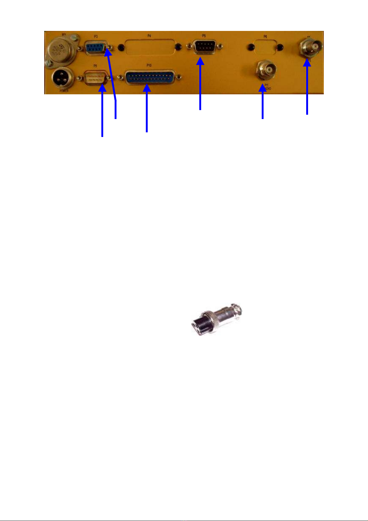
The GPS antenna connects to the system via a standard B C plug to P7 on the rear panel of
the DTS2. Use an aircraft certified GPS antenna.
Raw GPS data from the on board module is sent out on serial RS232 port P9 at 9600 baud.
The Raw GPS MEA –0813 sentence string looks like this:
$GPRMC,111621.00,A,3402.78600,S,01849.77818,E,0.039,249.04,101007,,,A*78
$GPGGA,111621.00,3402.78600,S,01849.77818,E,1,08,1.79,212.9,M,32.7,M,,*45
This string output from DTS2 can be connected directly to another data systems RS232
Serial port such as ADAS2000 or DMT and SEA data systems.
7.4 Connecting Analog Signals To The System
Warning !! Make sure that the analog voltages connected to the system do not exceed
+-10 Volts.
Analog signals can be connected to the 9 pin D type connector P5 at the rear of the DTS. Use
RG178 coax cable or shielded Teflon cable for each signal connection. Bad, unshielded or
incorrect connections will result in noisy data.
Analog input channel 5 in Numbers
0 6
1 1
2 7
3 2
4 8
5 3
6 9
7 4
GROU D 5
Selecting the ADC input voltage range.
Jumper BR19 to BR26 are used to select between the -5 to +5 Volt
range or the -10 to +10 Volt range.
Link pins 1 to 2 for the -5 to +5 Volt range.
Link pins 2 to 3 for the -10 to +10 Volt range. * Default on all channels, Do not change the
default settings without consulting ESD.
7.5 Connecting arallel I/O To The System
Warning !! Do not connect signals that exceed +-28V to the counter and parallel input
channels, a minimum of 5 Volts is needed to switch the circuit.
The user can connect flare fire buttons to the counter channels to keep track of how many
flares were fired. The counter channels have software de-bounce filters, each counter will
increment when applying a momentary voltage to the appropriate counter input pin on P10.
The user can also set a software de-bounce value in the configuration file.
NOTE: Keep Counter Channels separate from each other and from other parallel I/O
signals. Cross talk in a multi core ca le can cause a counter channel to increment when
the other channel is pulsed. Use single core shielded ca le for counter channels.

10
COU TER_DEBOU CE parameter and counter TIMEOUT parameter are used for switches
that are held on for several seconds and can be customized to accurately count the switch
closures when firing a flare..
The parallel inputs will change state from a 0 to a 1 when a voltage is applied to the
appropriate pin on P10.
The parallel inputs can be used to show the state of a switch etc.
Parallel input and output signals can e connected to the 25 pin D connector P10
BR34 Header Pin Num er P10 D Connector Pin Num er Signal Name
1 13 Counter 0 *
2 25 Counter 1 *
3 12 IP 4
4 24 IP 3 *
5 11 IP 7
6 23 IP 5
7 10 IP 6
8 22 IP 2 *
9 9 OP0
10 21 OP1
11 8 OP2
12 20 OP3
13 7 OP4
14 19 OP5
15 6 GP6
16 18 GP7
17 5 GP8
18 17 GP9
19 4 GP10
20 16 GP11
21 3 GP12
22 15 GP13
23 2 GP14
24 14 GP15
25 1 G D
26 /C G D
The standard connections to the P/IO port for counting flares are the following:
Connect Burn In Place ( BIP ) flare fire button to COU TER0 and Ejectable ( EJT ) flare fire
button to COU TER1. If Acetone generators are used these can be connected to IP2 and IP3.
The counter and Parallel I/O inputs to DTS2 can take from 5V to 28V inputs.
When the fire button is pressed to fire a flare the connection from the button to DTS2 must go
from 0V to +V. i.e. A voltage must be applied momentarily to enable the system to count the
flares.

11
7.6 Flags
There are 4 software Flags, each Flag is attached to one of the counter channels.
Flag0 is attached to Counter0, Flag1 is attached to Counter1 etc. The Flag will go from 0 to 1
when the corresponding Counter increments and will stay a 1 for the number of seconds that
the user specified in the CFG file - (FLAG_O _TIME) parameter. The Flags can be used to
indicate that a flare is burning and the user can specify the burn time of the flare.
8. The Status LED’s
On the front panel of the DTS2 there are 8 LED’s
LED # Color Name
1 Yellow ot Used.
2 Red TX, flashes when DTS2 Transmits data.
3 Yellow ot Used.
4 Green The GRX LED will flash once per second as the system gets
updated GPS data even if the GPS data is not valid. This
indicates GPS data is being received by the system.
5 Yellow Data ot Valid will light up to show that the GPS data is not
valid ( This can happen if the GPS does not detect enough
Satellites ).
6 Red System Running. This LED will flash rapidly to indicate that
the DTS2 software is running.
PWR Red Lights up to show that power is on.
HDD Red Lights up each time there is Compact Flash DISK Read or
Write.
9 Status ort
The Status port P3 is used to output serial RS232 data to a Laptop or Tablet PC.
The Data string sent on this port has the leading characters $PDS before the data and is
terminated with CR/LF. The Default Baud Rate for this port is 19200. This can be changed to
another baud rate if needed.
The PDS string looks like this:
$PDS,ZBMU,2007,10,10,11,14,08, -34.0464,+018.8296,00662,000,1007,0,0,0,0,000,000,001.23,001.20,001.24,6A,!!
The string is exactly the same as the string that gets sent to TITA and that is written to file
except it has the text header $PDS in the beginning and a check sum at the end.
3 and 9 Serial output uses a crossover serial cable to communicate with other data
collection equipment such as DMT data system or ADAS2000 and ADAS4.
Cable connections are shown below.

12
Example of connections between DTS2 and other systems using a crossover serial cable.
3 sends the DS data string to ADAS4 and 9 sends the raw G S NMEA strings to
ADAS2000. If a laptop is used it can be connected to 3.
10 Display
This version of DTS2 does not have a VGA output for connection to a monitor.
11 Configuring The System
OTE: The system BIOS setup and defaults are fixed and the user cannot change these
settings. BIOS settings are factory defined and are automatically refreshed at power up.
11.1 Setting up the Radio.
Important !! set the radio frequency well away from that used by other organization and
make sure that the frequency you use does not interfere with other users. It is the
responsibility of the user to arrange the frequency allocation for their systems from the
FCC in your country.
11.2 Radio rogramming software.
WinA4p program is used to configure the radio. Instructions on the use of WinA4p is
included in the HELP menu of the software and a separate PDF file. NOTE: WinA4p is the
copyright of RF Data Tech. If any changes are made to the Radio settings you must first
consult with ESD.
Before Running WinA4p set the rotary switches on the modem both to 0 0 with a small screw driver
The following screens show the default settings for DTS2:
P3 P9
Serial Crossover Cables
DTS
ADAS2000
COM 1
ADAS4
COM 1
PDS String
MEA Strings

13
Note that the Base Station modem must be setup with 0.5 Watt transmit power as shown
below:
The default “over air” baud rate is setup at 4800 BPS, this can be changed to lower or higher
baud rate but should not be done without consulting with ESD. ote that the Serial port
setting is 19200 Baud , this should also not be changed by the user.

14
11.3 Compact Flash (CF) Files
Warning !! Do not eject/insert the Compact Flash
cartridge while power is on.
First switch off power efore removing or inserting a
Flashdisk
otherwise the cartridge will definitely e damaged.
Typical CF disk.
The DTS2 software expects that there should be a CF card inserted in the slot for Data
Storage. Without a CF inserted in the system it will not be possible to store data but the DTS2
will continue to function normally and transmit data.
Note that the CF card is inserted upside down in the DTS2
slot.
The CF card must have a file on it called C_DRIVE.TST.
The Text contents of this file look like this:
This is a dummy test file so that DTS2 can check the Compact Flash drive (CF).
! DO OT REMOVE THIS FILE FROM THE CF !
This File is only used by DTS2 software to check that there is a CF inserted. If the CF is not
inserted then the DTS2 will send out the error message on the status RS232 Com Port 3 ( P3)
“ Cannot Access C drive” DTS2 will run normally but no data will be stored. Do not delete
this file from the CF.
If the CF is present then DTS2 will output the message “C drive access OK”
If the DTS2 software is updated with a newer version and ESD sends you a new EXE and/or
CFG file then this new file must be copied onto the CF .
The file name of the DTS2 software is app.exe ( application.exe ).
The configuration file is called app.cfg ( application configuration ).
These files should be copied onto the CF card and the CF card must be inserted into the slot
B: ( Make sure that power is off when removing or inserting the CF card )
Power up the DTS2 and the new files will automatically be copied from the CF drive to the
on board “A“drive ( ote : the A drive is a virtual drive on the DTS2 CPU hardware). After
the new files have been copied by the above process the CF can be removed ( First power off
the DTS2 before removinbg the CF card ). When the DTS2 is powered up again after the
above procedure the DTS2 will use the new version of the software and/or configuration.
A Laptop running a terminal emulator ( T2, Hyper term etc ) can e used to monitor the
status messages on port P3 to check that the software has in fact een upgraded. The
version num er of the software will e shown in the message from the DTS2 when it
powers up.

15
The files that should e on the CF card for software update are shown elow when the
CF card is inserted into a card reader on a Win XP machine.
11.4 Configuring DTS2.
The DTS2 can be user configured by editing the text file A .CFG on the Compact Flash
(CF) card. When the DTS2 boots it checks for a new configuration file on the CF card and
copies this file to the on board A drive, the DTS2 then loads this new configuration at run
time. If there is no new configuration file on the CF DTS2 will use the existing configuration
file that is already loaded on the on board virtual “A” drive.
NOTE: Use only capital letters in the CFG file.
The Following is an example of the APP.CFG file:
HEADER
BASE Cape_Town_RSA
LAT -34.0465
LNG +018.82 3
AC_ID ZBMU
TX_TIME_SLOT 0
TX_SPACING 4
PDS_FILE_STORAGE
DISK ON
ID C
LOG_AFTER 1
RAW_FILE_STORAGE
DISK OFF
ID C
LOG_AFTER 1
FLR_FILE_STORAGE
DISK OFF
ID C
AUXS1
SWITCH ON
COM_PORT 4
BAUD_RATE 1 200
SIO
SWITCH ON
COM_PORT 3
BAUD_RATE 1 200
SEND_RATE 1
GPS
SWITCH ON
COM_PORT 1
BAUD_RATE 600

16
MODEM
SWITCH ON
COM_PORT 2
BAUD_RATE 1 200
PTT_ON_TIME 1
PTT_OFF_TIME 1
CHECK_CD_BEFORE_TX NO
ERROR_CHECKI G YES
ADC
SWITCH ON
SAMPLE_RATE_PER_SEC 8
CHANNEL..cOFFSET...cSLOPE...vOFFSET...vSLOPE...NAME
00 2048 204.8 0.0 2.0 RMT
01 2048 204.8 0.0 2.0 STP
02 2048 204.8 0.0 2.0 PTP
03 2048 204.8 0.0 2.0 OFF
04 2048 204.8 0.0 1.0 OFF
05 2048 204.8 0.0 1.0 OFF
06 2048 204.8 0.0 1.0 OFF
07 2048 204.8 0.0 1.0 OFF
PIO
SWITCH ON
CHANNEL.................….NAME
COUNTER0 BIP
TIMEOUT0 2
COUNTER1 EJT
TIMEOUT1 1
COUNTER2 OFF
TIMEOUT2 1
COUNTER3 OFF
TIMEOUT2 1
COUNTER_DEBOUNCE 10
PI0 R_BURN
PI1 L_BURN
PI2 OFF
PI3 OFF
FLAGS
FLAG......................NAME
FLAG0 BIP
FLAG0_ON_TIME 10
FLAG1 EJT
FLAG1_ON_TIME 7
FLAG2 OFF
FLAG2_ON_TIME 1
FLAG3 OFF
FLAG3_ON_TIME 1
DISPLAY
SWITCH OFF
LICENCE
NUMBER 0D 02865
Making changes to the A .CFG file
The CF card must be inserted into a Laptop or into a USB - Card reader.
The File app.cfg is a TEXT file and can be opened with OTEPAD. NB: Do not open the
file with Microsoft Word !
The text can be changed and then the file closed and saved.

17
11.5 The Airborne system CFG File A .CFG explained.
HEADER
BASE Bethlehem,South_Africa
LAT +28.123
LNG -028.321
AC_ID ZJRA
TX_TIME_SLOT 0
TX_SPACING 4
BASE: can be any text describing the project base of operations. The text must not be longer than 20
characters and must be continuous without spaces.
LAT: The BASE Latitude in dd mm.mmm format.
L G: The BASE Longitude in ddd mm.mmm format.
AC_ID: The alpha numeric text description of the aircraft .
TX_TIME_SLOT and TX_SPACI G: (TX stands for Transmit ).
These two parameters warrant a detailed description. These parameters are use to determine when the Airborne
system is allowed to transmit its data. In a multiple aircraft network ( more than 1 aircraft ) the Airborne systems
must not transmit simultaneously otherwise data will be corrupted. To prevent this from happening the GPS time
PPS and seconds are use to space transmissions from the aircraft allowing each Airborne system to have a turn to
transmit its data.
If there are more than one Airborne systems in a network then a transmission from each system will only be
allowed after the other systems have transmitted their data. Spacing the transmissions by use of the GPS time
seconds is a convenient way of doing this. If for example there are 4 aircraft in the network each system will only
be allowed to transmit every 4
th
second.
The first Airborne system (A) will have the following settings:
TX_TIME_SLOT = 0 and TX_SPACI G = 4.
The second Airborne system (B) will have the following settings:
TX_TIME_SLOT = 1 and TX_SPACI G = 4.
The third Airborne system (C) will have the following settings:
TX_TIME_SLOT = 2 and TX_SPACI G = 4.
The fourth Airborne system (D) will have the following settings:
TX_TIME_SLOT = 3 and TX_SPACI G = 4.
A will transmit on second 00,04,08,12,16,20,,,,,,,, etc
B will transmit on second 01,05,09,13,17,21,,,,,,,, etc
C will transmit on second 02,06,10,14,18,22,,,,,,,, etc
D will transmit on second 03,07,11,15,19,23,,,,,,,, etc
As can be seen from above, The Base Station will receive data on every second with each Airborne system
transmitting every 4
th
second.
It is recommended to have a 2 second spacing of transmissions from the Airborne system. In this case a 4 aircraft
network settings will be the following:
The first Airborne system (A) will have the following settings:
TX_TIME_SLOT = 0 and TX_SPACI G = 8.
The second Airborne system (B) will have the following settings:
TX_TIME_SLOT = 2 and TX_SPACI G = 8.
The third Airborne system (C) will have the following settings:
TX_TIME_SLOT = 4 and TX_SPACI G = 8.
The fourth Airborne system (D) will have the following settings:
TX_TIME_SLOT = 6 and TX_SPACI G = 8.
A will transmit on second 00,08,16,24,32,40,,,,,,,, etc
B will transmit on second 02,10,18,26,34,42,,,,,,,, etc
C will transmit on second 04,12,20,28,36,44,,,,,,,, etc
D will transmit on second 06,14,22,30,38,46,,,,,,,,,etc
The Base Station will receive data once every 2 seconds and each Airborne systems will transmit every 8
seconds.

18
In a 2 aircraft network with a 2 second spacing between transmissions the setting will be the following:
The first Airborne system (A) will have the following settings:
TX_TIME_SLOT = 0 and TX_SPACI G =4.
The second Airborne system (B) will have the following settings:
TX_TIME_SLOT = 2 and TX_SPACI G = 4.
This configuration can be confusing so it is advise to call or email ESD for help when changing your network to
accommodate new aircraft.
A will transmit on second 00,04,08,12,16,20,,,,,,,, etc
B will transmit on second 02,06,10,14,18,22,,,,,,,, etc
PDS_FILE_STORAGE
DISK ON
ID C
LOG_AFTER 1
The PDS ( Packet Data String ) that is sent from the Airborne system to the Base Station can also be saved on the
PCMCIA card of the Airborne system. This is recommended for post flight data analysis.
The DISK can be set to O or OFF. Setting this parameter to OFF will not open an output file.
ID specifies the drive ID which can only be “C”. The CF card will be drive C on this system.
The LOG_AFTER parameter specifies how often the record must be written to disk. Once every second ( The
maximum rate ) will be set to a 1, once every 2 seconds will be set to a 2, etc.
Due to the volume of data it is recommended to set this parameter to 10 for every 10 seconds.
RAW_FILE_STORAGE
DISK OFF
ID C
LOG_AFTER 1
The Raw data file format is explained later on in this manual.
The same applies to this file as explained above. This option is not usually used and can be set to OFF as a
default.
FLR_FILE_STORAGE
DISK OFF
ID C
The FLR_FILE_STORAGE is file that gets written to only when a flare is fired.
This file will contain one PDS record each time a flare gets fired. The user can do post flight analysis on this data
which will yield exact time and place the flare was fired. If the DISK is set to OFF then the file will not be
created. The disk ID as with the other files must be specified as “C”.
AUXS1
SWITCH OFF
COM_PORT 4
BAUD_RATE 19200
Auxilary Serial I/O is not implemented on standard software and should be flagged to OFF.
SIO
SWITCH ON
COM_PORT 3
BAUD_RATE 19200
SEND_RATE 1
SIO is an auxiliary Serial Input Output port only available on some custom setup DTS2 units.
The PDS is also sent out on this port if it is enabled ( set to O ). Always leave this set to OFF.
COM_PORT can be set to 3,4 ,5 or 6. The com port settings have been factory set on this version of DTS2, leave
these default settings as they are. BAUD_RATE is the RS232 RX/TX speed, Leave this setting at 19200.
SE D_RATE is how frequently the system must send data out on the SIO port. 1 is once per second 2 is once
every 2 seconds

19
GPS
SWITCH ON
COM_PORT 1
BAUD_RATE 9600
GPS is the RS232 Com port that the GPS is connected to.
The SWITCH parameter should always be set to O .
The GPS used as a default COM_PORT 1 and this setting should not be changed by the user.
The Current version of DTS2 uses 9600 baud for communicating with the GPS module.
MODEM
SWITCH ON
COM_PORT 2
BAUD_RATE 19200
PTT_ON_TIME 150
PTT_OFF_TIME 40
CHECK_CD_BEFORE_TX NO
ERROR_CHECKING YES
The SWITCH parameter must always be set to O .
Com Port 2 is the default port for the Radio Modem communications and should not be changed by the
user. The baud rate on this version of DTS2 is set to 19200 default but can be changed.
The PTT_O _TIME is the time from when the DTS2 asserts the Push To Talk on the radio before it
starts sending data. This is a factory set parameter and should never be changed by the user.
PTT_OFF_TIME is the time that must elapse after a transmission of data before the PTT of the radio is de
asserted. This parameter should also not be changed by the user.
CHECK_CD_BEFORE_TX is used to listen out for other transmissions before transmitting.
This parameter should always be set to O with this version of DTS2.
ERROR_CHECKI G can be set to YES or O. If it is set to a yes on the Airborne unit then it must be set to a
YES on the Base Station. This parameter enables a CHECK SUM error detection. Leave this parameter set to
YES.
ADC
SWITCH ON
SAMPLE_RATE_PER_SEC 8
CHANNEL..cOFFSET...cSLOPE...vOFFSET...vSLOPE....NAME
00 2048 204.8 2.5 0.05 TEMP
01 2048 204.8 0.0 0.01 HUM
02 2048 204.8 0.0 00.1 PRESS
03 2048 204.8 0.0 1.0 OFF
04 2048 204.8 0.0 1.0 OFF
05 2048 204.8 0.0 1.0 OFF
06 2048 204.8 0.0 1.0 OFF
07 2048 204.8 0.0 1.0 OFF
ADC is the Analog To Digital converter of the DTS2.
A variety of analog sensors can be connected to the DTS2 ADC input channels.
The SWITCH parameter can be set to O or OFF if no analog sensors are connected.
The ADC Offset and Slope are discussed in greater detail on page 22 ote 1.

20
PIO
SWITCH ON
CHANNEL.................…................NAME
COUNTER0 BIP
TIMEOUT 2
COUNTER1 EJT
TIMEOUT 1
COUNTER2 OFF
TIMEOUT 1
COUNTER3 OFF
TIMEOUT 1
COUNTER_DEBOUNCE 10
PIO L_BURN
PI1 R_BURN
PI2 OFF
PI3 OFF
PIO is the Parallel I/O ports and counter channels of the DTS2.
Switch should always be set to on.
COU TER0 can have a name attached to it. Any alpha numeric text, maximum 8 characters long to describe the
counter usage. In the example above the name BIP is attached to COU TER0. This stands for Burn In Place
flares.
The TIMEOUT parameter specifies the length of time in seconds that the system must ignore any further pulses
on the Counter channel after the first pules has been received.
This acts as an extended switch bounce lock out to prevent the counter from incrementing from switch bounce or
the switch being hit several times to fire a flare.
If the TIMEOUT parameter has been set to 4 then the maximum rate that a flare can be fired on that channel
is once every 4 seconds. If the operator fires 2 flares in succession before the 4 seconds timeout has elapsed then
the counter will increment only once.
The person firing the flares has to be informed as to the correct firing procedures which will match the way the
DTS2 has been configured.
The TIMEOUT parameter can be set from any number from 0 to 20 suitable to the specific aircraft flare rack and
firing method.
The above description is applicable to COU TER0, 1 ,2 and 3.
The COU TER_DEBOU CE parameter is a general de bounce lock out and must not be a number greater than
50. This parameter blocks out or de bounces the small transitions at the beginning and end of the switch closure.
PI0 parallel port 0 can have a text label attached to it to describe the channel use.
ot more than 8 characters long. In the example L_BUR is the label for PI0, this is the Left Burn
Acetone generator on the aircraft.
If a parallel input is not used then the user must set it to OFF in the parameter field.
The same explanation applies to the other parallel input ports PI1,2 and 3.
FLAGS
FLAG............................................NAME
FLAG0 BIP
FLAG0_ON_TIME 90
FLAG1 EJT
FLAG1_ON_TIME 7
FLAG2 OFF
FLAG2_ON_TIME 1
FLAG3 OFF
FLAG3_ON_TIME 60
Table of contents
Other ESD Recording Equipment manuals

ESD
ESD CAN-PCI/405 User manual

ESD
ESD CAN-CBX-THERMO User manual

ESD
ESD CAN-ISA/331 User manual

ESD
ESD ECS-XMC User manual

ESD
ESD CPCI-USB-5 User manual

ESD
ESD CPCI-CAN/400-2 User manual

ESD
ESD CAN-CBM-CLOCK User manual

ESD
ESD CAN-PCI/402 User manual

ESD
ESD CAN-PC104/331 Instruction manual

ESD
ESD CAN-PCI/405-B4 User manual

ESD
ESD CPCI-CAN/331 Instruction manual

ESD
ESD CAN-PCI104/200 User manual

ESD
ESD CPCI-CAN/400-4 User manual

ESD
ESD CAN-USB/3-FD User manual

ESD
ESD CAN-PC104/200 Instruction manual

ESD
ESD C.2076.63 User manual

ESD
ESD CAN - PCC User manual

ESD
ESD PMC-CAN/331-3.3 Instruction manual

ESD
ESD ECS-PCIe/1100 User manual

ESD
ESD VME - ASIO16 User manual