Table of contents
1. Overview......................................................................................................................................6
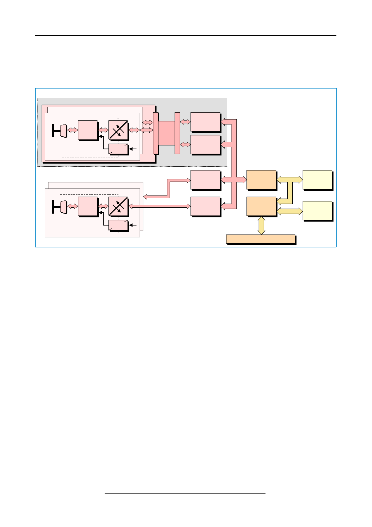
1.1 Module Description................................................................................................................6
2. Hardware Installation....................................................................................................................7
2.1 Procedure..............................................................................................................................7
2.2 PCB View with Connectors....................................................................................................9
2.3 LEDs and Connectors in the Slot Cover...............................................................................10
2.4 CAN-PCI/405-4 Version with 4 CAN Interfaces....................................................................11
3. Technical Data............................................................................................................................12
3.1 General Technical Data........................................................................................................12
3.2 Microprocessor and Memory................................................................................................12
3.3 PCI Bus................................................................................................................................13
3.4 CAN Interface......................................................................................................................13
3.5 Software Support.................................................................................................................14
4. Connector Assignments..............................................................................................................15
4.1 CAN Interface at DSUB9 Connector....................................................................................15
4.2 Connection to Adapter Board (CAN-PCI/405-4 only)...........................................................16
5. Correctly Wiring Electrically Isolated CAN Networks..................................................................17
5.1 Light Industrial Environment (Single Twisted Pair Cable).....................................................17
5.1.1 General Rules.............................................................................................................17
5.1.2 Cabling........................................................................................................................18
5.1.3 Termination..................................................................................................................18
5.2 Heavy Industrial Environment (Double Twisted Pair Cable).................................................19
5.2.1 General Rules.............................................................................................................19
5.2.2 Device Cabling............................................................................................................20
5.2.3 Termination..................................................................................................................20
5.3 Electrical Grounding.............................................................................................................21
5.4 Bus Length...........................................................................................................................21
5.5 Examples for CAN Cables...................................................................................................22
5.5.1 Cable for Light Industrial Environment Applications (Two-Wire)..................................22
5.5.2 Cable for Heavy Industrial Environment Applications (Four-Wire)...............................22
6. CAN Troubleshooting Guide.......................................................................................................23
6.1 Termination..........................................................................................................................23
6.2 Electrical Grounding.............................................................................................................24
6.3 Short Circuit in CAN Wiring..................................................................................................24
6.4 CAN_H/CAN_L-Voltage ......................................................................................................24
6.5 CAN Transceiver Resistance Test .......................................................................................25
7. Declaration of Conformity...........................................................................................................26
8. Order Information.......................................................................................................................27
CAN-PCI/405 Hardware Manual • Doc. No. C.2023.21 / Rev. 1.3 Page 5 of 28