ESD CAN-PC104/331 Instruction manual

CAN-PC104/331
PC/104-CAN-Interface
CAN-PC104/331-2
Hardware Installation
and
Technical Data
to Product C.2012.02, C.2012.04, C.2012.09
CAN-PC104 331 Hardware Manual • Doc. No.: C.2012.21 Rev. 1.6 Page 1 of 32
esd electronic system design gmbh
Vahrenwalder Str 207 • 30165 Hannover • Germany
http://www esd eu
Phone: +49 (0) 511 3 72 98-0 • Fax: +49 (0) 511 3 72 98-68

N O T E
The information in this document has been carefully checked and is believed to be entirely reliable.
esd makes no warranty of any kind with regard to the material in this document, and assumes no
responsibility for any errors that may appear in this document. In particular descriptions and
technical data specified in this document may not be constituted to be guaranteed product features
in any legal sense.
esd reserves the right to make changes without notice to this, or any of its products, to improve
reliability, performance or design.
All rights to this documentation are reserved by esd. Distribution to third parties, and reproduction
of this document in any form, whole or in part, are subject to esd's written approval.
© 2015 esd electronic system design gmbh, Hannover
esd electronic system design gmbh
Vahrenwalder Str. 207
30165 Hannover
Germany
Phone: +49-511-372 98-0
Fax: +49-511-372 98-68
E-Mail: [email protected]
Internet: www.esd.eu
This manual contains important information and instructions on safe and efficient
handling of the CAN-PC104 331. Carefully read this manual before commencing any
work and follow the instructions.
The manual is a product component, please retain it for future use.
Trademark Notices
CANopen® and CiA® are registered community trademarks of CAN in Automation e.V.
Windows is a registered trademark of Microsoft Corporation in the United States and other countries.
The PICMG® name and logo are registered trademarks of the PCI Industrial Computer Manufacturers Group.
All other trademarks, product names, company names or company logos used in this manual are reserved by their
respective owners.
Page 2 of 32 Hardware Manual • Doc. No.: C.2012.21 Rev. 1.6 CAN-PC104 331

Document file I:\Texte\Doku\MANUALS\CAN\PC104331\CAN-PC104-331_Hardware_en_16.odt
Date of print 2015-12-07
Document type
number DOC0800
Hardware version CAN-PC104 Rev. 1.2
Document History
The changes in the document listed below affect changes in the hardware as well as changes in
the description of the facts, only.
Rev. Chapter Changes versus previous version Date
1.5 1.3 New chapter ‘Connector Position and Board Dimensions’. 2002-02-25
5. New chapter ‘Version CAN-PC104 xxx-Micromatch’
1.6
- Safety Instructions and classification inserted
2015-12-07
2.2 Chapter revised
3.3 DeviceNet option deleted
3.4 Chapter updated
4.3 DeviceNet option deleted
5. Description of cable revised
5.2 Note revised
6. Chapter revised
8. Chapter “Order Information” moved and revised
Technical details are subject to change without further notice.
CAN-PC104 331 Hardware Manual • Doc. No.: C.2012.21 Rev. 1.6 Page 3 of 32

Classification of Warning Messages and Safety Instructions
This manual contains noticeable descriptions, warning messages and safety instructions, which
you must follow to avoid personal injuries or death and property damage.
This is the safety alert symbol.
It is used to alert you to potential personal injury hazards. Obey all safety messages
and instructions that follow this symbol to avoid possible injury or death.
DANGER, WARNING, CAUTION
Depending on the hazard level the signal words DANGER, WARNING or CAUTION are used to
highlight safety instructions and warning messages. These messages may also include a warning
relating to property damage.
DANGER
Danger statements indicate a hazardous situation which, if not avoided, will result in
death or serious injury.
WARNING
Warning statements indicate a hazardous situation that, if not avoided, could result in
death or serious injury.
CAUTION
Caution statements indicate a hazardous situation that, if not avoided, could result in
minor or moderate injury.
NOTICE
Notice statements are used to notify people on hazards that could result in things other than
personal injury, like property damage.
NOTICE
This NOTICE statement indicates that the device contains components sensitive to
electrostatic discharge.
NOTICE
This NOTICE statement contains the general mandatory sign and gives information that
must be heeded and complied with for a safe use.
INFORMATION
INFORMATION
Notes to point out something important or useful.
Page 4 of 32 Hardware Manual • Doc. No.: C.2012.21 Rev. 1.6 CAN-PC104 331

Safety Instructions
● When working with the CAN-PC104 331 follow the instructions below and read the manual
carefully to protect yourself from injury and the CAN-PC104 331 from damage.
● The device is a built-in component. It is essential to ensure that the device is mounted in a way
that cannot lead to endangering or injury of persons or damage to objects.
● Do not use damaged or defective cables to connect the CAN-PC104 331 and follow the CAN
wiring hints in chapter: "Correct Wiring of Electrically Isolated CAN Networks".
● In case of damages to the device, which might affect safety, appropriate and immediate
measures must be taken, that exclude an endangerment of persons and domestic animals and
property.
● Current circuits which are connected to the device have to be sufficiently protected against
hazardous voltage (SELV according to EN 60950-1).
● The CAN-PC104 331 may only be driven by power supply current circuits, that are contact
protected. A power supply, that provides a safety extra-low voltage (SELV) according to
EN 60950-1, complies with this conditions.
● The device has to be securely installed in the control cabinet before commissioning.
● Protect the CAN-PC104 331 from dust, moisture and steam.
● Protect the CAN-PC104 331 from shocks and vibrations.
● The CAN-PC104 331 may become warm during normal use. Always allow adequate ventilation
around the CAN-PC104 331 and use care when handling.
● Do not operate the CAN-PC104 331 adjacent to heat sources and do not expose it to
unnecessary thermal radiation. Ensure an ambient temperature as specified in the technical
data.
DANGER
Hazardous Voltage - Risk of electric shock due to unintentional contact with
uninsulated live parts with high voltages inside of the system into which the CAN-
PC104 331 is to be integrated.
→ Disconnect all hazardous voltages (mains voltage) before opening the system.
→ Ensure the absence of voltage before starting any electrical work
NOTICE
Electrostatic discharges may cause damage to electronic components.
To avoid this, perform the steps described on page 11 before you touch the CAN-
PC104 331, in order to discharge the static electricity from your body.
Qualified Personal
This documentation is directed exclusively towards personal qualified in control and automation
engineering.
The installation and commissioning of the product may only be carried out by qualified personal,
which is authorized to put devices, systems and electric circuits into operation according to the
applicable national standards of safety engineering.
CAN-PC104 331 Hardware Manual • Doc. No.: C.2012.21 Rev. 1.6 Page 5 of 32

Intended Use
The intended use of the CAN-PC104 331 is the operation as PC 104-CAN-Interface.
The guarantee given by esd does not cover damages which result from improper use, usage not in
accordance with regulations or disregard of safety instructions and warnings.
● The CAN-PC104 331 is intended for indoor installation only.
● The operation of the CAN-PC104 331 in hazardous areas, or areas exposed to potentially
explosive materials is not permitted.
● The operation of the CAN-PC104 331 for medical purposes is prohibited.
Service Note
The CAN-PC104 331 does not contain any parts that require maintenance by the user. The CAN-
PC104 331 does not require any manual configuration of the hardware. Unauthorized intervention
in the device voids warranty claims.
Disposal
Devices which have become defective in the long run have to be disposed in an appropriate way or
have to be returned to the manufacturer for proper disposal. Please, make a contribution to
environmental protection.
Number Representation
All numbers in this document are base 10 unless designated otherwise. Hexadecimal numbers
have a prefix of 0x. For example, 42 is represented as 0x2A in hexadecimal.
Page 6 of 32 Hardware Manual • Doc. No.: C.2012.21 Rev. 1.6 CAN-PC104 331

Table of contents
Safety Instructions...........................................................................................................................5
1. Overview......................................................................................................................................8
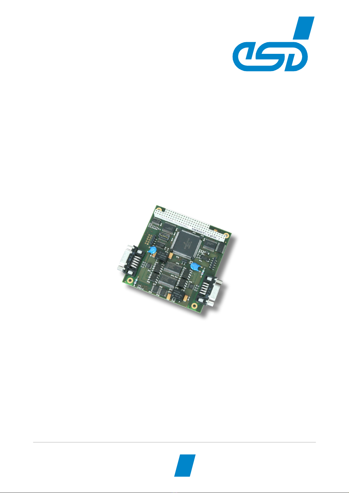
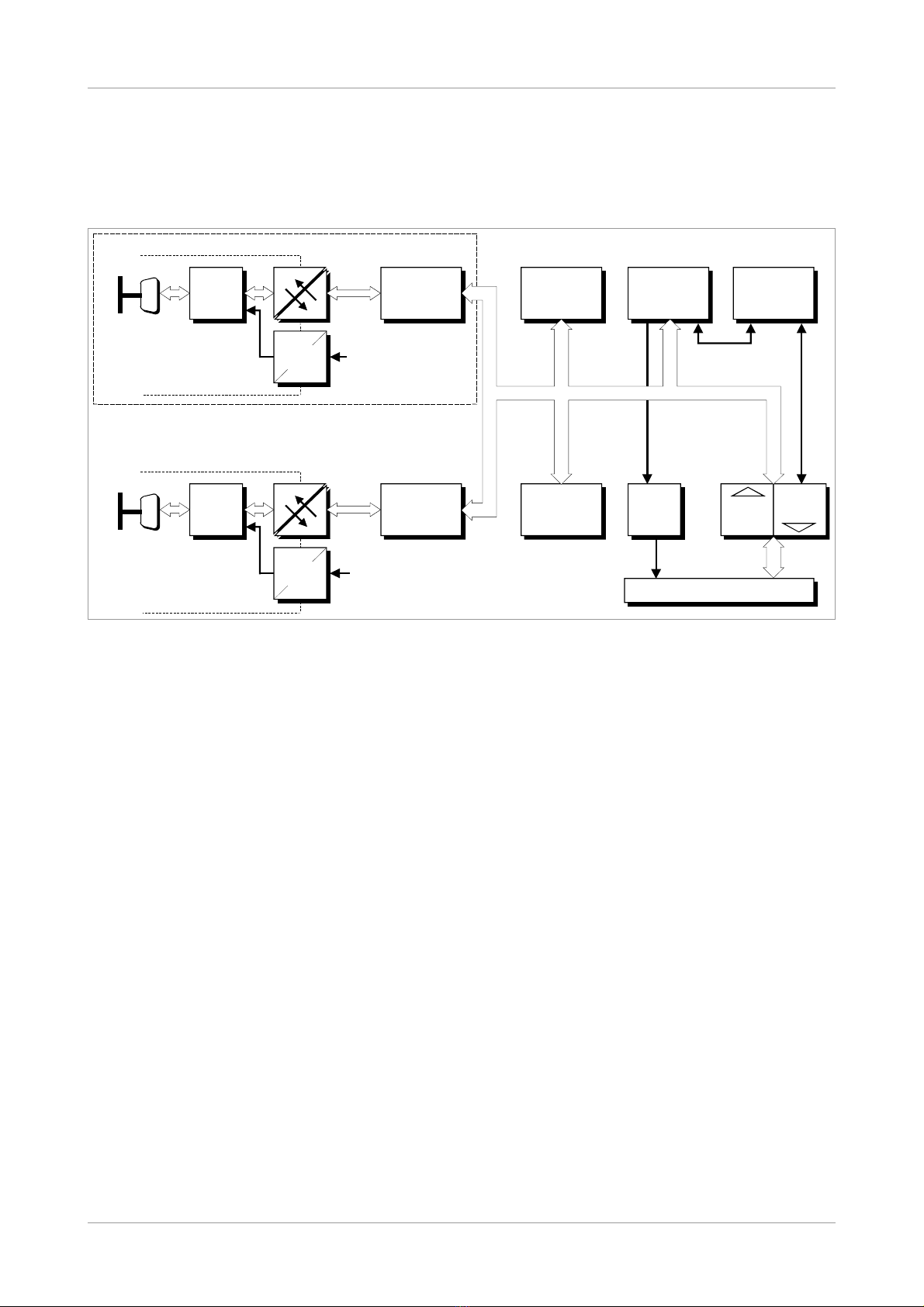
1.1 Description of the Module......................................................................................................8
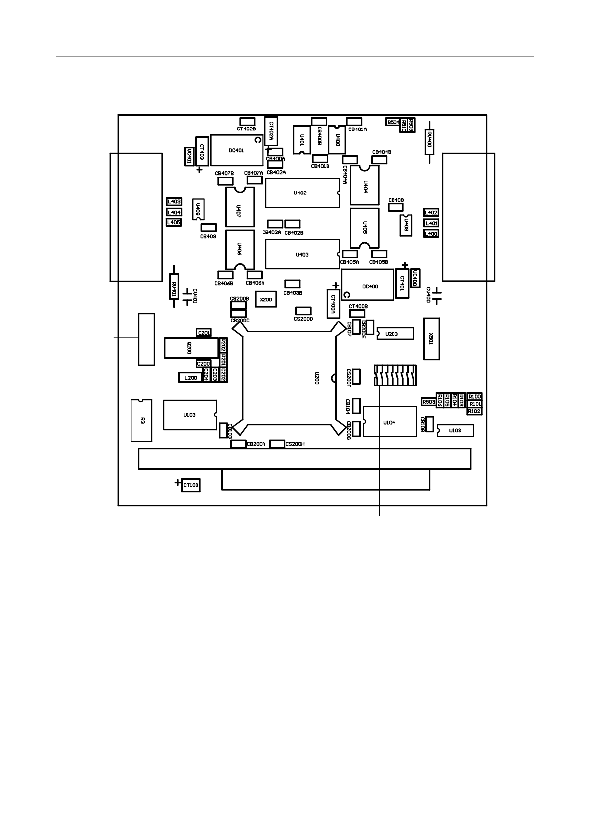
1.2 PCB View with Connectors....................................................................................................9
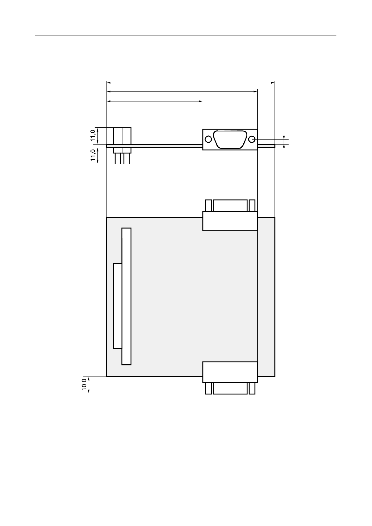
1.3 Connector Position and Board Dimensions..........................................................................10
2. Hardware Installation..................................................................................................................11
2.1 Before Starting Hardware Installation...................................................................................11
2.2 Execute Hardware Installation and Setting of PC 104-Bus Address.....................................12
3. Technical Data............................................................................................................................15
3.1 General Technical Data........................................................................................................15
3.2 PC 104 Bus..........................................................................................................................15
3.3 CAN Interface......................................................................................................................16
3.4 Software Support.................................................................................................................16
4. Connector Pin Assignment.........................................................................................................17
4.1 CAN Bus Interface at DSUB9 (X400, X401)........................................................................17
5. Version CAN-PC104 331-2-Micro-Match....................................................................................18
5.1 Overview..............................................................................................................................18
5.2 Pin Assignment Micro-Match Socket....................................................................................19
5.3 Adapter Cable Micro-Match (male) to DSUB9(male)............................................................20
6. Correct Wiring of Electrically Isolated CAN Networks.................................................................21
6.1 Standards concerning CAN Wiring......................................................................................21
6.2 Light Industrial Environment (Single Twisted Pair Cable).....................................................22
6.2.1 General Rules.............................................................................................................22
6.2.2 Cabling........................................................................................................................23
6.2.3 Termination..................................................................................................................23
6.3 Heavy Industrial Environment (Double Twisted Pair Cable).................................................24
6.3.1 General Rules.............................................................................................................24
6.3.2 Device Cabling............................................................................................................25
6.3.3 Termination..................................................................................................................25
6.4 Electrical Grounding.............................................................................................................26
6.5 Bus Length...........................................................................................................................26
6.6 Examples for CAN Cables...................................................................................................27
6.6.1 Cable for light industrial Environment Applications (Two-Wire)....................................27
6.6.2 Cable for heavy industrial Environment Applications (Four-Wire)................................27
7. CAN Troubleshooting Guide.......................................................................................................28
7.1 Termination..........................................................................................................................28
7.2 Electrical Grounding.............................................................................................................29
7.3 Short Circuit in CAN Wiring..................................................................................................29
7.4 CAN_H CAN_L-Voltage ......................................................................................................29
7.5 CAN Transceiver Resistance Test........................................................................................30
7.6 Support by esd.....................................................................................................................30
8. Order Information.......................................................................................................................31
CAN-PC104 331 Hardware Manual • Doc. No.: C.2012.21 Rev. 1.6 Page 7 of 32

Overview
1. Overview
1.1 Description of the Module
Figure 1 Block circuit diagram of CAN-PC104 331-2
The CAN-PC104 board is a CAN module designed for the PC 104-bus (PC 104 16 bits). It uses a
68331 microcontroller, which cares for the local management. The CAN data is buffered in a local
SRAM. Security and consistency of data is guaranteed up to 1 Mbit s.
The ISO 11898 compliant CAN interface allows a data-transfer rate of a maximum of 1 Mbit s.
Among many other features, the bit rate can be set by software.
The CAN interface is electrically separated from other voltage potentials by means of optocouplers
and DC DC converters.
In the CAN-PC104-331-2-MicroMatch option, the CAN interfaces are equipped with Micro-Match
sockets instead of the DSUB-9 connectors.
Page 8 of 32 Hardware Manual • Doc. No.: C.2012.21 Rev. 1.6 CAN-PC104 331
+5 V=
+5 V=
Microcontroller
68331
SRAM Arbiter
+5 V=
+5 V=
C
A
N
B
U
S
CAN
CAN
C
A
N
B
U
S
electrical isolation
DC/DC
Converter
DSUB
CiA pinning
CAN Controller
SJA1000
Flash EPROM
electrical isolation
DC/DC
Converter
DSUB
CiA pinning
PC/104 Connector
FIFO
512 bytes
Tx Data
FIFO
512 bytes
Rx Data
IRQ
Physical
CAN
Layer
CAN Controller
SJA1000
2. CAN Interface
only at
CAN-PC104/331-2
Physical
CAN
Layer

Overview
1.2 PCB View with Connectors
Figure 2 View of PCB layer CAN-PC104 331-2 (without a front panel)
CAN-PC104 331 Hardware Manual • Doc. No.: C.2012.21 Rev. 1.6 Page 9 of 32
CAN 1
X401 CAN 0
X400
X100
X101
S100
16 9
8 1
X201
BDM-Interface

Overview
1.3 Connector Position and Board Dimensions
All listed values are given in millimetre.
Figure 3 CAN-PC104 331-2 technical drawing
Page 10 of 32 Hardware Manual • Doc. No.: C.2012.21 Rev. 1.6 CAN-PC104 331
DSUB
55,0
86,0
6,0
3,6

Hardware Installation
2. Hardware Installation
2.1 Before Starting Hardware Installation
During the hardware installation it may be necessary to change the PC 104-I O-port address. The
default address is 0x1E0...0x1E7. The CAN module covers 8 data bytes. Furthermore it is
necessary to set the interrupt during the following software installation.
Make sure that there will be no address conflict with other boards of the PC/104-systems
and that there will be no conflict with other interrupts!
Windows NT/2000/XP Users
In order to avoid address and interrupt conflicts, the used address ranges should be checked
before starting the hardware installation.
This can be done in Windows NT 4.0 e.g. by selecting Programs Administrative Tools (Common)
Windows NT Diagnostics. In the dialogue box Windows NT Diagnostics call Resources and there
select I/O Port. A list with the used and available address ranges appears.
Make sure that the default value of the CAN-PC104 331 is in a free memory area. If it is not, note
one free memory area (which corresponds to the choices stated in fig. 2.2.2) and change the
CAN-PC104 331 address by means of the coding switch during the hardware installation
described below.
In the same dialogue box call Interrupts. A list with the used interrupt lines appears. Note a free
interrupt, because you have to select an interrupt for the CAN module during the software
installation. (The complete software installation sequence is described in the software manual
‘NTCAN-API, Part 2: Installation Guide’.)
Windows 9x/ME Users
If you use a Windows 9x ME operating system first read the software installation guide in the
appendix of the manual ‘NTCAN API, Part 2: Installation Guide’ and then start with the installation
sequence!
CAN-PC104 331 Hardware Manual • Doc. No.: C.2012.21 Rev. 1.6 Page 11 of 32

Hardware Installation
2.2 Execute Hardware Installation and Setting of PC/104-Bus Address
The CAN-PC104 331 module can be used in all PC 104-compatible 16-bit systems (e.g. portable
industry PCs or installed control systems). The carrier system will therefore be described by the
general term ‘computer’ below.
NOTICE
Read the safety instructions at the beginning of this document carefully, before
you start with the hardware installation!
DANGER
Hazardous Voltage - Risk of electric shock due to unintentional contact with
uninsulated live parts with high voltages inside of the computer into which the CAN-
PC104 331 is to be integrated.
→ Disconnect all hazardous voltages (mains voltage) before opening the computer.
→ Ensure the absence of voltage before starting any electrical work.
NOTICE
Electrostatic discharges may cause damage to electronic components.
In order to avoid this please follow the instructions below before touching the CAN
module:
→ Switch off the power supply of your computer but leave it connected to mains to make
sure that the computer case remains earthed.
→ Then touch the metal case of the computer to discharge your static electricity.
→ Furthermore, you should prevent your clothes from touching the CAN-PC104 331,
because your clothes might be electrostatically charged as well.
Procedure
1. Switch off your computer and all connected peripheral devices (monitor, printer, etc.). Switch
off the connected CAN devices of the network the CAN module is to be connected to.
2. Discharge your body as described above if not yet done.
3. Disconnect the power supply of the computer from the mains.
DANGER
Hazardous Voltage
Risk of electric shock due to unintentional contact with uninsulated live parts with
high voltages.
→
→
→
Disconnect all hazardous voltages (mains voltage) before opening the computer.
If the computer does not have a flexible mains cable, but is directly connected to
mains, disconnect the power supply via the safety fuse and make sure that the
fuse cannot switch on again unintentionally (i.e. with caution label).
Ensure the absence of voltage before starting any electrical work
4. Remove the computer cover.
5. Select a free position in the PC 104-bus stack.
There are no restrictions in choosing a position in the stack for this module as long as there
are only 16-bit modules between it and the CPU.
6. Make sure that there will be no address conflict with other PC 104 boards. (See chapter
'Before Starting Hardware Installation' above.)
Page 12 of 32 Hardware Manual • Doc. No.: C.2012.21 Rev. 1.6 CAN-PC104 331

Hardware Installation
If you have to change the address of the board, go on with step 7 otherwise go on with step
8.
7. Setting the PC 104-bus-I O-port address
The address is set via the coding switch S100. Its position can be taken from figure 2 on
page 9.
If a coding switch is set to ‘OFF’, the according address is evaluated as ‘1'. If it set to ‘ON’,
the according address is evaluated as ‘0'.
Coding switch: 1
2
3
4
5
6
7
8
ON
PC 104-port address: A9 A8 A7 A6 A5 A4 A3 --
OFF
Table 1 Coding switch S100
The hardware address has to be given to the driver during the software installation. The
menu of the installation program offers a choice of the following addresses:
Figure 4 Default setting of coding switches and choices of addresses supported by
installation program
The installation program does not support any other coding switch positions.
If you use a Windows 9x ME operating system, you have to set the coding switches as
proposed by the Windows-Hardware Wizard.
8. Install the CAN module at the selected PC 104-stack position.
9. Close the computer case.
10. Connect the CAN wire.
Please note that the CAN bus must be terminated at both ends.
Additionally, the CAN_GND must be connected to earth at exactly one point in the CAN
network. Use the special T- connectors and terminator connectors offered by esd.
A CAN device whose CAN interface is not electrically isolated acts as an earth connection
like the CAN_GND.
Please pay attention to the notes on correct wiring of CAN networks (see from page 25)!
The first CAN interface (CAN network 0) is connected via the DSUB connector (X400) and
the second CAN interface (CAN network 1) is connected via the DSUB connector (X401).
CAN-PC104 331 Hardware Manual • Doc. No.: C.2012.21 Rev. 1.6 Page 13 of 32
0x100 - 0x107 HEX
0x250 - 0x257 HEX
0x2A0 - 0x2A7 HEX
0x3 0 - 0x3 7 HEX
0x3F0 - 0x3F7 HEX
0x1E0 - 0x1E7 HEX
0x1E8 - 0x1EF HEX
1 2 3 4 5 6 7 8
OFF
1 2 3 4 5 6 7 8
OFF
12345678
OFF
1 2 3 4 5 6 7 8
OFF
1 2 3 4 5 6 7 8
OFF
1 2 3 4 5 6 7 8
OFF
12345678
OFF
Default Setting
Coding switch = 'ON'
(address bit = 0)
Coding switch = 'OFF'
(address bit = 1)
Coding switch =
don't care

Hardware Installation
If you use the CAN-PC104 331-MicroMatch-version, please read chapter “Version CAN-
PC104 331-2-Micro-Match” from page 18 for further information.
11. Connect the computer to mains again (mains connector or safety fuse).
12. Switch on the power supply of the computer, the peripheral devices and the other CAN
devices again.
13. End of hardware installation.
Continue with the software installation as described in the manual ‘NTCAN-API, Installation
Guide’.
Page 14 of 32 Hardware Manual • Doc. No.: C.2012.21 Rev. 1.6 CAN-PC104 331

Technical Data
3. Technical Data
3.1 General Technical Data
Ambient
temperature 0...50°C
Humidity 90 %, non-condensing
Power Supply
via PC 104-bus,
nominal voltage: 5 V ±5%,
current (typ. at 20°C): for 1x CAN: 0.55 A
for 2x CAN: 0.70 A
Connectors
X100 (64-pole PC 104 PCB connector) - PC 104 bus
X101 (40-pole PC 104 PCB connector) - PC 104 bus
X400 (DSUB9 male) - CAN interface 1 (net 0) (C.2012.02, C.2012.04)
X401 (DSUB9 male) - optional CAN interface 2 (net 1) (C.2012.04 only)
X400 (MicroMatch socket) - CAN interface 1 (net 0) (C.2012.09 only)
X401 (MicroMatch socket) - CAN interface 2 (net 1) (C.2012.09 only)
The following connectors are only equipped for programming and service:
X200 (4-pole female con. - CPU interface (serial, TTL)
X201 (10-pole male connector) - BDM interface
X501 (5-pole male con.) - ISP programming
Dimensions 95.9 mm x 90.2 mm
Weight 1x CAN: 85 g
2x CAN: 95 g
Table 2 General technical data
3.2 PC/104 Bus
Host bus PC 104
PC 104-data bus 16 bit
Interface IN OUT-FIFOs (512 bytes each)
Interrupt 1 out of 12
Stack position no restrictions in position in stack
Connectors PC 104 PCB connectors, 40-pole and 64-pole
Table 3 PC 104 bus data
CAN-PC104 331 Hardware Manual • Doc. No.: C.2012.21 Rev. 1.6 Page 15 of 32

Technical Data
3.3 CAN Interface
Number
CAN-PC104 331-1: 1 CAN interface via DSUB connector
CAN-PC104 331-2: 2 CAN interfaces via DSUB connector
CAN-PC104 331-2 MicroMatch: 2 CAN interfaces via MircoMatch
sockets
CAN controller SJA1000
CAN protocol ISO 11898-1 (Basic-CAN2.0A B)
Physical interface physical layer in accordance with ISO 11898-2,
transfer rate programmable from 10 Kbit s to 1 Mbit s
Bus termination has to be set externally
Electrical isolation of the
CAN interface from other
units
separation of CAN interfaces from each other and from PC 104-bus
potentials by optocouplers and DC DC converters
Table 4 Data of the CAN interface
3.4 Software Support
Software drivers are available for Windows®, Linux®, VxWorks® and QNX® systems.
Other drivers are available on request.
The firmware can be loaded from the PC into the Flash EPROM.
INFORMATION
The CAN layer 2 (NTCAN-API) software installation and the software drivers are
described in the NTCAN-API manual (esd-order No.: C.2001.21):
“NTCAN-API Part 1: Application Developers manual” and
“NTCAN-API Part 2: Installation Guide”
CANopen® and J1939 protocol libraries are available.
Page 16 of 32 Hardware Manual • Doc. No.: C.2012.21 Rev. 1.6 CAN-PC104 331

Connector Pin Assignment
4. Connector Pin Assignment
4.1 CAN Bus Interface at DSUB9 (X400, X401)
The signals are identically assigned to the connector of CAN net 0 interface (X400) and optional
CAN net 1 interface (X401). The connectors are male 9-pole DSUB connectors.
Device connector 9-pin DSUB connector, male
Pin Position
Pin Assignment
Signal Pin Signal
1
reserved
CANx_GND
6
2
CANx_L
CANx_H
7
3
CANx_GND
reserved
8
4
reserved
reserved
9
5
Shield
Signal Description
CANx_L, CANx_H ... CAN signal lines of CAN net x (CAN-PC104 331-1: x ... 0
CAN-PC104 331-2: x ... 0, 1)
CANx_GND ... reference potential of the local CAN physical layer x
Shield ... shielding (connected with the case of the 9-pin DSUB connector)
reserved ... reserved for future applications, do not connect!
CAN-PC104 331 Hardware Manual • Doc. No.: C.2012.21 Rev. 1.6 Page 17 of 32
12345
6 7 8

Version CAN-PC104/331-2-Micro-Match
5. Version CAN-PC104/331-2-Micro-Match
5.1 Overview
This version of the PC104-module has got an AMP-Micro-Match socket instead of a DSUB9-CAN-
connectors. The socket is so small that it does not protrude the PCB, even if it is connected to a
plug. This is of great advantage, if the module is to be used in a narrow case.
An adapter cable is contained in delivery of CAN-PC104 331-2-MicroMatch (Order No.
C.2012.09). The cable with a length of 15 cm converts from micromatch connector to DSUB9. The
DSUB-connector of the adapter cable corresponds to the standard assignment of a 9-pin DSUB-
connector for CAN (see DSUB9-CAN-connectors).
NOTICE
The micromatch connector is not protected against wrong polarity!!
In order to prevent damage to property, the connecting cable must always be connected
as shown in the figure below!
Figure 5 View of CAN-PC104 331 Micro-Match
If you want to make the adapter cable yourself, you require the following information:
The AMP-socket used on the board has got the following designation:
AMP Micro-Match, FL, 10-pin, No. 8-215079-0
Page 18 of 32 Hardware Manual • Doc. No.: C.2012.21 Rev. 1.6 CAN-PC104 331

Version CAN-PC104/331-2-Micro-Match
The plug required, designed for use with standard flat-ribbon cables and crimp connection, has got
the following designation:
AMP Micro-Match, FRC, 10-pin, No. 8-215083-0
(available, e.g. from Farnell under order number 149-081)
The maximum length of the adapter cable including the externally connected cable to the T-
piece must not exceed 30 cm (ISO11898)!
5.2 Pin Assignment Micro-Match Socket
The following table shows the assignment of the Micro-Match socket on the board. Pin 6 of the
socket is not assigned.
Pin Assignment (View from Top Layer onto Connector)
Signal Pin Signal
reserved 1
6
not connected
7 CAN_GND
CAN_L 2 8 CAN_H
CAN_GND 3 9 reserved
reserved 4
10 reservedshield 5
10-pin AMD-Micro-Match socket
CAN-PC104 331 Hardware Manual • Doc. No.: C.2012.21 Rev. 1.6 Page 19 of 32

Version CAN-PC104/331-2-Micro-Match
5.3 Adapter Cable Micro-Match (male) to DSUB9(male)
The adapter cable is contained in delivery of CAN-PC104 331-2-Micro-Match (Order No.
C.2012.09). It consists of the two connectors and one flat-ribbon cable with 9 wires which is
crimped with wire 1 to pin 1 of the DSUB-connector at one end and with wire 1 to pin 1 of the
Micro-Match connector at the other end. The highest pin of the Micro-Match connector (pin 6) is
not assigned.
DSUB9-connector
(male) Pin
Flat-ribbon cable
signal
Micro-Match
connector
(male) Pin
1reserved 1
2CAN_L 2
3CAN_GND 3
4reserved 4
5shield 5
6
6CAN_GND 7
7CAN_H 8
8reserved 9
9reserved 10
Page 20 of 32 Hardware Manual • Doc. No.: C.2012.21 Rev. 1.6 CAN-PC104 331
Table of contents
Other ESD Recording Equipment manuals

ESD
ESD ECS-XMC User manual

ESD
ESD CPCI-ETH2 User manual

ESD
ESD ECS-PCIe/1100 User manual

ESD
ESD CAN-PCI/402 User manual

ESD
ESD CAN-USB/Micro User manual

ESD
ESD CAN-USB/3-FD User manual

ESD
ESD CAN - PCC User manual

ESD
ESD PMC-CAN/331-3.3 Instruction manual

ESD
ESD CAN-ISA/331 User manual

ESD
ESD C.2076.63 User manual

ESD
ESD CPCI-PN-DEV User manual

ESD
ESD DTS2 User manual

ESD
ESD CAN-PCI/266 User manual

ESD
ESD CPCI-CAN/400-4 User manual

ESD
ESD CPCI-CAN/331 Instruction manual

ESD
ESD CAN-PCI104/200 User manual

ESD
ESD CAN-PCI/405-B4 User manual

ESD
ESD CAN-PC104/200 Instruction manual

ESD
ESD VME - ASIO16 User manual

ESD
ESD DN-PC104/331 Instruction manual