ESD CPCI-CAN/400-4 User manual

CPCI-CAN/400-4
4 CAN Interfaces with ARINC825,
optional IRIG-B an
optional PXI-Interface
Hardware Manual
to Product C.2033.01, C.2033.04
CPCI-CAN/400-4 Hardware Manual • Doc. No.: C.2033.21 / ev. 1.2 Page 1 of 27
esd electronic system design gmbh
Vahrenwalder Str. 207 • 30165 Hannover • ermany
http://www.esd.eu
Phone: +49 (0) 511 3 72 98-0 • Fax: +49 (0) 511 3 72 98-68

N O T E
The information in this document has been carefully checked and is believed to be entirely reliable.
es makes no warranty of any kind with regard to the material in this document, and assumes no
responsibility for any errors that may appear in this document. In particular descriptions and
technical data specified in this document may not be constituted to be guaranteed product features
in any legal sense.
es reserves the right to make changes without notice to this, or any of its products, to improve
reliability, performance or design.
All rights to this documentation are reserved by es . Distribution to third parties, and reproduction
of this document in any form, whole or in part, are subject to es 's written approval.
© 2015 esd electronic system design gmbh, Hannover
esd electronic system design gmbh
Vahrenwalder Str. 207
30165 Hannover
Germany
Phone: +49-511-372 98-0
Fax: +49-511-372 98-68
E-Mail: [email protected]
Internet: www.esd.eu
Trademark Notices
CANopen® and CiA® are registered community trademarks of CAN in Automation e.V.
Windows® is a registered trademark of Microsoft Corporation in the United States and other countries.
The PICMG® name and logo are registered trademarks of the PCI Industrial Computer Manufacturers Group.
CompactPCI® is a registered trademark of the PCI Industrial Computers Manufacturers Group.
All other trademarks, product names, company names or company logos used in this manual are reserved by their
respective owners.
Page 2 of 27 Hardware Manual • Doc. No.: C.2033.21 / ev. 1.2 CPCI-CAN/400-4

Document file: I:\Texte\Doku\MANUALS\CPCI\CPCI-CAN400\CPCI-CAN400-4\Englisch\CPCI-CAN400-
4_Hardware_en_12.odt
Date of print: 2015-11-11
Document type
number: DOC0800
Har ware version: 1.0
Document History
The changes in the document listed below affect changes in the hardware as well as changes in
the description of the facts, only.
Revision Chapter Changes versus previous version Date
1.0 - First English version 2011-08-01
1.1
- Safety instructions revised
2013-04-19
1. Block circuit diagram new
5.1 Values of current consumption corrected,
P1, P2 renamed to J1, J2, pin number corrected
10. Order information revised
1.2
- Safety instructions revised
2015-11-11
3. Step 8. - Note about CAN termination inserted
5.1 Absolute maximum power and description of additional front panel added
5.5 OnTime TOS-32 and J1939 protocol libraries added
9. Declaration of Conformity updated
10. Order Information revised
Technical details are subject to change without further notice.
CPCI-CAN/400-4 Hardware Manual • Doc. No.: C.2033.21 / ev. 1.2 Page 3 of 27

Safety Instructions
● When working with CPCI-CAN/400-4 follow the instructions below and read the manual carefully to protect yourself
from injury and the CPCI-CAN/400-4 from damage.
● The device is a built-in component. It is essential to ensure that the device is mounted in a way that cannot lead to
endangering or injury of persons or damage to objects.
● The device has to be securely installed in the control cabinet before commissioning.
● Protect the CPCI-CAN/400-4 from dust, moisture and steam.
● Protect the CPCI-CAN/400-4 from shocks and vibrations.
● The CPCI-CAN/400-4 may become warm during normal use. Always allow adequate ventilation around the CPCI-
CAN/400-4 and use care when handling.
● Do not operate the CPCI-CAN/400-4 adjacent to heat sources and do not expose it to unnecessary thermal radiation.
Ensure an ambient temperature as specified in the technical data.
● Do not use damaged or defective cables to connect the CPCI-CAN/400-4 and follow the CAN wiring hints in chapter:
"Correctly Wiring Electrically Isolated CAN Networks".
● In case of damages to the device, which might affect safety, appropriate and immediate measures must be taken, that
exclude an endangerment of persons and domestic animals and property.
● Current circuits which are connected to the device have to be sufficiently protected against hazardous voltage (SELV
according to EN 60950-1).
● The CPCI-CAN/400-4 may only be driven by power supply current circuits, that are contact protected.
A power supply, that provides a safety extra-low voltage (SELV or PELV) according to EN 60950-1, complies with this
conditions.
Attention !
Electrostatic ischarges may cause amage to electronic components.
To avoid this, please perform the steps described on page 8 before you touch the CPCI-
CAN/400-4, in order to discharge the static electricity from your body.
Qualifie Personal
This documentation is directed exclusively towards personal qualified in control and automation engineering.
The installation and commissioning of the product may only be carried out by qualified personal, which is
authorized to put devices, systems and electric circuits into operation according to the applicable national
standards of safety engineering.
Conformity
The CPCI-CAN/400-4 is an industrial product and meets the demands of the EU regulations and EMC
standards printed in the conformity declaration at the end of this manual.
Inten e Use
The intended use of the CPCI-CAN/400-4 is the operation as CompactPCI-CAN interface in a CompactPCI
system.
The guarantee given by esd does not cover damages which result from improper use, usage not in
accordance with regulations or disregard of safety instructions and warnings.
!The CPCI-CAN/400-4 is intended for installation in a CompactPCI system only.
!The operation of the CPCI-CAN/400-4 in hazardous areas, or areas exposed to potentially explosive
materials is not permitted.
!The operation of the CPCI-CAN/400-4 for medical purposes is prohibited.
Service Note
The CPCI-CAN/400-4 does not contain any parts that require maintenance by the user. The CPCI-CAN/400-
4 does not require any manual configuration of the hardware.
Disposal
Devices which have become defective in the long run have to be disposed in an appropriate way or have to
be returned to the manufacturer for proper disposal. Please, make a contribution to environmental protection.
Page 4 of 27 Hardware Manual • Doc. No.: C.2033.21 / ev. 1.2 CPCI-CAN/400-4

Table of contents
1. Overview...................................................................................................................................... 6
2. PCB View with Connectors...........................................................................................................7
3. Hardware Installation....................................................................................................................8
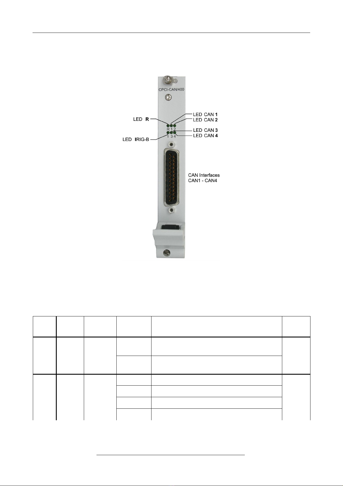
4. LEDs.......................................................................................................................................... 10
4.1 Position of the LEDS............................................................................................................10
4.2 LED Indication.....................................................................................................................10
5. Technical Data...........................................................................................................................12
5.1 General Technical Data.......................................................................................................12
5.2 Microprocessor and Memory................................................................................................12
5.3 CAN Interface......................................................................................................................13
5.4 CompactPCI Bus.................................................................................................................13
5.5 I IG-B Interface (Option).....................................................................................................13
5.6 Software Support.................................................................................................................14
6. Connector Assignments.............................................................................................................15
6.1 CAN.....................................................................................................................................15
7. Correctly Wiring Electrically Isolated CAN Networks..................................................................16
7.1 Standards concerning CAN Wiring......................................................................................16
7.2 Heavy Industrial Environment (Double Twisted Pair Cable).................................................17
7.2.1 General ules.............................................................................................................17
7.2.2 Device Cabling............................................................................................................18
7.2.3 Termination.................................................................................................................18
7.3 Light Industrial Environment (Single Twisted Pair Cable).....................................................19
7.3.1 General ules.............................................................................................................19
7.3.2 Cabling........................................................................................................................20
7.3.3 Termination.................................................................................................................20
7.4 Electrical Grounding.............................................................................................................21
7.5 Bus Length...........................................................................................................................21
7.6 Examples for CAN Cables...................................................................................................22
7.6.1 Cable for light industrial Environment Applications (Two-Wire)...................................22
7.6.2 Cable for heavy industrial Environment Applications (Four-Wire)................................22
8. CAN Troubleshooting Guide.......................................................................................................23
8.1 Termination..........................................................................................................................23
8.2 Electrical Grounding.............................................................................................................24
8.3 Short Circuit in CAN Wiring..................................................................................................24
8.4 CAN_H/CAN_L-Voltage ......................................................................................................24
8.5 CAN Transceiver esistance Test.......................................................................................25
8.6 Support by esd.....................................................................................................................25
9. Declaration of Conformity...........................................................................................................26
10. Order Information.....................................................................................................................27
CPCI-CAN/400-4 Hardware Manual • Doc. No.: C.2033.21 / ev. 1.2 Page 5 of 27

Overview
1. Overview
Figure 1: Block circuit diagram
The CPCI-CAN/400-4 is a CompactPCI® board in 3U format, that features four electrically isolated
high-speed CAN interfaces according to ISO 11898-2. CAN is driven by the esd Advanced CAN
Core (esdACC) CAN controller implemented in the Xilinx® Spartan® 3e FPGA.
The CPCI-CAN/400-4 provides high resolution hardware timestamps.
The CPCI-CAN/400-4 optionally features an I IG-B interface that offers inputs for analog or S-
422 I IG-B coded signals. Both are electrically isolated. I IG-B evaluation is controlled by an
additional microcontroller. I IG-B is used directly for CAN timestamping.
All I/Os are connected to a 25-pin DSUB connector in the front panel.
The CPCI-CAN-400-4 optionally features a PXI interface.
The signals T G 0-7, CLK 10 and STA are controlled via the FPGA. The signals LBL/LB 1-12
are looped through.
The PXI interface is available on request.
Page 6 of 27 Hardware Manual • Doc. No.: C.2033.21 / ev. 1.2 CPCI-CAN/400-4
4 x
CAN Core
with Timestamp
1x IRIG-B
FPGA
Xilinx Spartan-3
(32-Bit Microcontroller
MicroBlaze Option)
IRQ A
PCI Bridge
PLX PCI9056
CompactCI
Connector
RAM
optional FPGA-IO
PXI
Interface
RIO
Option
L Ds
lectrical Isolation
DC/DC
Converter
Physical
CAN Layer
ISO11898-2
CAN
and
IRIG-B
lectrical Isolation
DSUB25
4x CAN Interface
CAN
CAN
IRIG-B Input
CompactPCI
Front Panel
6 L Ds
CAN
CAN
A/D
Converter
Physical
IRIG-B Layer
RS-422
compati le
Physical
IRIG-B Layer
analog
IRIG-B
IRIG-B
Connector
RTC
Option I IG-B
8-Bit
Microcontroller
(8051)

PCB View with Connectors
2. PCB View with Connectors
Figure 2: PCB top view
Attention:
The jumper (JP600A) has to be left in delivery status!
Otherwise the software driver can not be started.
See also page 15 for signal assignment of the CAN connector.
CPCI-CAN/400-4 Hardware Manual • Doc. No.: C.2033.21 / ev. 1.2 Page 7 of 27

Har ware Installation
3. Har ware Installation
Rea the safety instructions at the beginning of this ocument carefully,
before you start with the har ware installation!
Danger!
Electric shock risk. Never carry out work while power supply voltage is switched on!
Attention !
Electrostatic discharges may cause damage to electronic components. To avoid
this, please perform the following steps before you touch the CPCI-CAN/400-4, in
order to discharge the static electricity from your body:
Switch off the power of your computer, but leave it connected to the mains until
you have discharged yourself (if applicable).
Please touch the metal case of the computer now to discharge yourself.
Furthermore, you should prevent your clothes from touching the computer,
because your clothes might be electrostatically charged as well.
Proce ure:
1. Switch off your computer and all connected peripheral devices (monitor, printer, etc.).
2. Discharge your body as described above.
3. Disconnect the computer from the mains.
If the computer does not have a flexible mains cable, but is directly connected to mains,
disconnect the power supply via the safety fuse and make sure that the fuse cannot switch
on again unintentionally (i.e. with caution label).
Danger!
Never carry out work while power supply voltage is switched on!
4. Open the case.
5. Insert the CPCI-CAN/400-4 board into a free CompactPCI slot in your computer.
6. Close the computer case again.
7. Fix the CPCI-CAN/400-4 board with the screws on the front panel.
8. Connect the CAN interfaces via the DSUB25 connector in the front panel of the CPCI-
CAN/400-4 (see page 7).
Please note that the CAN bus has to be terminated at both ends! esd offers special T-
connectors and termination connectors. Additionally the CAN_GND signal has to be
connected to earth at exactly one point in the CAN network.
A CAN participant with a CAN interface which is not electrically isolated corresponds to the
grounding of the CAN-GND.
Page 8 of 27 Hardware Manual • Doc. No.: C.2033.21 / ev. 1.2 CPCI-CAN/400-4

Har ware Installation
9. Connect the computer to mains again (mains connector or safety fuse).
10. Switch on the computer and the peripheral devices.
11. End of hardware installation.
CPCI-CAN/400-4 Hardware Manual • Doc. No.: C.2033.21 / ev. 1.2 Page 9 of 27

LEDs
4. LEDs
4.1 Position of the LEDS
Figure 3: Connectors and LEDs
4.2 LED In ication
LED Colour Function In icator
State Description
LED name
in schematic
diagram
Rgreen Power
off CPCI-CAN/400-4 not ready, FPGA not
loaded LED301A
on CPCI-CAN/400-4 is ready for operation,
FPGA is loaded
Igreen I IG-B
off -
LED300A
flickering no I IG-B signal
blinking CPCI-CAN/400-4 synchronises with I IG-B
on I IG-B time synchronised
Table 1: Description of LEDs and I
Page 10 of 27 Hardware Manual • Doc. No.: C.2033.21 / ev. 1.2 CPCI-CAN/400-4

LEDs
LED Colour Function In icator
State Description
LED name
in schematic
diagram
1green CAN1
Traffic
off no CAN traffic on CAN 1 LED301B
blinking CAN traffic on CAN 2
2green CAN2
Traffic
off no CAN traffic on CAN 2 LED301C
blinking CAN traffic on CAN 2
3green CAN3
Traffic
off no CAN traffic on CAN 3 LED300B
blinking CAN traffic on CAN 3
4green CAN4
Traffic
off no CAN traffic on CAN 4 LED300C
blinking CAN traffic on CAN 4
Table 2: Description of CAN LEDs
CPCI-CAN/400-4 Hardware Manual • Doc. No.: C.2033.21 / ev. 1.2 Page 11 of 27

Technical Data
5. Technical Data
5.1 General Technical Data
Power supply
voltage
via CompactPCI bus:
nominal voltage: 3.3 V (5V tolerant),
typical current consumption (incl. CAN traffic):
at 5 V: 265 mA
at 3.3V: 175 mA (FPGA not booted)
265 mA (FPGA booted)
Absolute maximum power at 3.3V (Imax.3.3V = 1A): Pmax:3.3 = 3.3W
Connectors
CAN0 ... CAN3
J1
J2
(X600, 25-pin DSUB) - CAN Interfaces CAN0-CAN3,
optional I IG-B
CompactPCI board connector
(X100, 110-pin male connector)
CompactPCI board connector
(X101, 110-pin male connector)
Only for test- and programming purposes:
X303 reserved for future use
Temperature
range 0...50 °C ambient temperature
Humidity max. 90%, non-condensing
Dimensions PCB only: 100 mm x 160 mm
Weight 235 g
Table 3: General data of the module
5.2 Microprocessor an Memory
Block AM (FPGA) 72 KB
D AM 64 MB
Table 4: Microprocessor and Memory
Page 12 of 27 Hardware Manual • Doc. No.: C.2033.21 / ev. 1.2 CPCI-CAN/400-4

Technical Data
5.3 CAN Interface
Number of CAN
interfaces 4
CAN controller esdACC in FPGA Spartan® 3e,
acc. to ISO 11898-1 (CAN 2.0 A/B)
CAN protocol according to ISO 11898-1
Physical Layer High-speed CAN interface according to ISO 11898-2,
bit rate up to 1 Mbit/s
Electrical isolation
via digital isolator and DC/DC converter,
500 V (effective) between CAN potential and module-system-potential
with pollution degree 1
Bus termination terminating resistor has to be set externally, if required
Connector DSUB25 (male)
Table 5: Data of the CAN interface
5.4 CompactPCI Bus
Host bus PCI-Bus according to PCI Local Bus Specification 2.2
PCI-data/address bus 32 Bit, 33/66 MHz
Microprocessor optional 32-bit µC in FPGA (MicroBlaze)
Board dimension according to CompactPCI-Specification, ev. 2.2
Connector
Connector coding Universal-Board, not keyed
(3.3 V or 5 V signalling voltage)
Table 6: Data of the CompactPCI bus
5.5 IRIG-B Interface (Option)
Number
1x analog and 1x S-422 compatible (via front panel, both electrically
isolated),
1x S-422 compatible (at J2 only)
Controller 8051 microcontroller
Connector DSUB25
Table 7: Data of the serial interface
CPCI-CAN/400-4 Hardware Manual • Doc. No.: C.2033.21 / ev. 1.2 Page 13 of 27

Technical Data
5.6 Software Support
CAN layer 2 (CAN-API) software drivers are available for Windows®, VxWorks®1, QNX®, TX1
Linux®1 and On Time TOS-321 . Drivers for other operating systems are available on request.
Multiple higher layer protocols are available.
The CANopen® software package is available for Windows, VxWorks, Linux, QNX and TX.
A INC 825 as another higher layer protocol is available as an option for Windows, VxWorks, QNX,
Linux and TX.
J1939 protocol libraries are available for Windows, others on request.
1 For detailed information about the driver availability of your special operating system please contact our sales team.
Page 14 of 27 Hardware Manual • Doc. No.: C.2033.21 / ev. 1.2 CPCI-CAN/400-4

Connector Assignments
6. Connector Assignments
6.1 CAN
Device connector: 25-pin DSUB connector, male
Pin Position:
Pin Assignment:
Signal Pin Signal
1
CAN_0_L
CAN_0_H
14
2
CAN_0_GND
reserved
15
3
reserved
CAN_1_L
16
4
CAN_1_H
CAN_1_GND
17
5
reserved
reserved
18
6
CAN_2_L
CAN_2_H
19
7
CAN_2_GND
reserved
20
8
reserved
CAN_3_L
21
9
CAN_3_H
CAN_3_GND
22
10
reserved
reserved
23
11
reserved
I IG-B_ x+ (optional)
24
12
I IG-B_ x- (optional)
I IG_B_A+ (optional)
25
13
I IG-B_A- (optional)
Shield
S
Signal Description:
CAN_Y_L, CAN_Y_H ... CAN signal lines of CAN interface Y (Y = 0, 1, 2, 3)
CAN_Y_GND ... reference potential of the local CAN physical layer Y (Y = 0, 1, 2, 3)
Shield ... shielding (connected with the case of the 25-pin DSUB connector)
reserved ... reserved for future applications, do not connect!
I IG-B_ x+, I IG-B_ x-... optional I IG-B signal lines
I IG-B_A+, I IG-B_A- ... optional I IG-B signal lines
CPCI-CAN/400-4 Hardware Manual • Doc. No.: C.2033.21 / ev. 1.2 Page 15 of 27
1 13
22
2 3 4 5 6 7 8 9 10 11 12
25242317 1814 15 16 2019 21

Correctly Wiring Electrically Isolate CAN Networks
7. Correctly Wiring Electrically Isolate CAN Networks
For the CAN wiring all applicable rules and regulations (EU, DIN), e.g. regarding electromagnetic
compatibility, security distances, cable cross-section or material, have to be met.
7.1 Stan ar s concerning CAN Wiring
The flexibility in CAN network design is one of the key strengths of the various extensions and
additional standards like e.g. CANopen, A INC825, DeviceNet and NMEA2000 that have been
built on the original ISO 11898-2 CAN standard. In using this flexibility comes the responsibility of
good network design and balancing these tradeoffs.
Many CAN organizations and standards have scaled the use of CAN for applications outside the
original ISO 11898. They have made system level tradeoffs for data rate, cable length, and
parasitic loading of the bus.
However for CAN network design margin must be given for signal loss across the complete system
and cabling, parasitic loadings, network imbalances, ground offsets against earth potential and
signal integrity. Therefore the practical maximum number of no es, bus length an stub
length are typically much lower.
esd has concentrated her recommendations concerning CAN wiring on the specifications of the
ISO 11898-2. Thus this wiring hints forgoes to describe the special features of the derived
standards CANopen, A INC825, DeviceNet and NMEA2000.
The consistent compliance to ISO 11898-2 offers significant advantages:
●Durable operation due to well proven design specifications
●Minimizing potential failures due to sufficient margin to physical limits
●Trouble-free maintenance during future network modifications or during fault diagnostics
due to lack of exceptions
Of course reliable networks can be designed according the specifications of CANopen, A INC825,
DeviceNet and NMEA2000, however it must be observe that it is strictly not recommen e
to mix the wiring gui elines of the various specifications!
Page 16 of 27 Hardware Manual • Doc. No.: C.2033.21 / ev. 1.2 CPCI-CAN/400-4

Correctly Wiring Electrically Isolate CAN Networks
7.2 Heavy In ustrial Environment (Double Twiste Pair Cable)
7.2.1 General Rules
NOTICE
esd only grants the compliance with directive 2014/30/EU, if the CAN wiring is carried out
with single shielded ouble twiste pair cables that match the requirements of
ISO 11898-2.
The following general rules for the CAN wiring with single shielded double twisted pair cable
should be followed:
1A cable type with a wave impedance of about 120 Ω ±10% with an adequate conductor cross-section
(≥ 0.22 mm²) has to be used. The voltage drop over the wire has to be considered.
2For heavy industrial environment use a four-wire CAN cable.
Connect
•
•
•
two twisted wires to the data signals (CAN_H, CAN_L) and
the other two twisted wires to the reference potential (CAN_GND) and
the cable shield to functional earth (FE) at least at one point.
3The reference potential CAN_GND has to be connected to the functional earth (FE) at exactly one
point.
4A CAN bus line must not branch (exception: short cable stubs) and has to be terminated with the
characteristic impedance of the line (generally 120 Ω ±10%) at both ends (between the signals CAN_L
and CAN_H and not to CAN_GND).
5Keep cable stubs as short as possible (l < 0.3 m).
6Select a working combination of bit rate and cable length.
7Keep away CAN cables from disturbing sources. If this can not be avoided, double shielded cables are
recommended.
Figure 4: CAN wiring for heavy industrial environment
CPCI-CAN/400-4 Hardware Manual • Doc. No.: C.2033.21 / ev. 1.2 Page 17 of 27
CAN GND
CAN_L
CAN_H
CAN_GND
n.c.
n.c.
n.c.
n.c.
n.c.
n.c.
n.c.
n.c.
n.c.
n.c.
CAN_L
CAN_H CAN_GND
Shield
CAN_GND
twisted twisted
5
6
7
9
8
1
4
3
2
9
1
4
5
6
7
3
8
2
n.c.
n.c.
Single shielded
double twisted pair cable
(four-wire cable,
x x 0. mm²)
wire shield
Wire Layout
( xample)
Signal assignment of single shielded double twisted pair cable
with earth and termination
n.c. = not connected
DSUB9 connector
(female or male)
pin desi nation
connector case
DSUB9 connector
(female or male)
pin desi nation
CAN cable with connectors
connector case
earth (F )

Correctly Wiring Electrically Isolate CAN Networks
7.2.2 Device Cabling
NOTICE
If single shielded double twisted pair cables are used, realize the T-connections by means
of connectors that support connection of two CAN cables at one connector where the
cable’s shield is looped through e.g. DSUB9 connector from E NI (E BIC CAN BUS
MAX, order no.:154039).
The usage of esd’s T-connector type C.1311.03 is not recommended for single shielded
double twisted pair cables because the shield potential of the conductive DSUB housing is
not looped through this T-connector type.
If a mixed application of single twisted and double twisted cables is unavoidable, take care
that the CAN_GND line is not interrupted!
Figure 5: Example of proper wiring with single shielded double twisted pair cables
7.2.3 Termination
●A termination resistor has to be connected at both ends of the CAN bus.
If an integrated CAN termination resistor which is equipped at the CAN interface at the end
of the bus is connected, this one has to be used for termination instead of an external CAN
termination plug.
●9-pin DSUB-termination connectors with integrated termination resistor and male and
female contacts (gender changer) are available from esd (order no. C.1303.01).
●9-pin DSUB-connectors with integrated switchable termination resistor can be ordered e.g.
from E NI (E BIC CAN BUS MAX, female contacts, order no.:154039).
Page 18 of 27 Hardware Manual • Doc. No.: C.2033.21 / ev. 1.2 CPCI-CAN/400-4

Correctly Wiring Electrically Isolate CAN Networks
7.3 Light In ustrial Environment (Single Twiste Pair Cable)
7.3.1 General Rules
NOTICE
esd only grants the compliance with directive 2014/30/EU, if the CAN wiring is carried out
with single shielded ouble twiste pair cables that match the requirements of
ISO 11898-2. See previous chapter: 'Heavy Industrial Environment (Double Twisted Pair
Cable)'.
The following general rules for CAN wiring with single shielded single twisted pair cable should be
followed:
1A cable type with a wave impedance of about 120 Ω ±10% with an adequate conductor cross-section
(≥ 0.22 mm²) has to be used. The voltage drop over the wire has to be considered.
2For light industrial environment use at least a two-wire CAN cable.
Connect
•
•
the two twisted wires to the data signals (CAN_H, CAN_L) and
the cable shield to the reference potential (CAN_GND).
3The reference potential CAN_GND has to be connected to the functional earth (FE) at exactly one
point.
4A CAN net must not branch (exception: short cable stubs) and has to be terminated with the
characteristic impedance of the line (generally 120 Ω ±10%) at both ends (between the signals CAN_L
and CAN_H and not at CAN_GND).
5Keep cable stubs as short as possible (l < 0.3 m).
6Select a working combination of bit rate and cable length.
7Keep away cables from disturbing sources. If this cannot be avoided, double shielded wires are
recommended.
Figure 6: CAN wiring for light industrial environment
CPCI-CAN/400-4 Hardware Manual • Doc. No.: C.2033.21 / ev. 1.2 Page 19 of 27
CAN GND
CAN_H
CAN_GND
n.c.
CAN_L 1
4
5
6
7
9
2
3
8
9
1
4
5
6
7
3
8
2
n.c.
n.c.
n.c.
n.c.
n.c.
n.c.
n.c.
n.c.
n.c.
n.c.
n.c.
n.c.
n.c.
earth (F )
CAN_L
CAN_H
CAN_GND
Single shielded
twisted pair cable
(two-wire cable,
1x x 0. mm²)
CAN_GND
(at wire shield)
Wire Layout
Signal assignment of single shielded twisted pair cable
with earth and termination
n.c. = not connected
DSUB9 connector
(female or male)
pin desi nation
connector case connector case
DSUB9 connector
(female or male)
pin desi nation
CAN wire with connectors

Correctly Wiring Electrically Isolate CAN Networks
7.3.2 Cabling
●To connect CAN devices with just one CAN connector per net use a short stub (< 0.3 m)
and a T-connector (available as accessory). If this devices are located at the end of the
CAN network, the CAN terminator “CAN-Termination-DSUB9” can be used.
Figure 7: Example for proper wiring with single shielded single twisted pair wires
7.3.3 Termination
●A termination resistor has to be connected at both ends of the CAN bus.
If an integrated CAN termination resistor which is equipped at the CAN interface at the end
of the bus is connected, this one has to be used for termination instead of an external CAN
termination plug.
●9-pin DSUB-termination connectors with integrated termination resistor and male and
female contacts (gender changer) are available from esd (order no. C.1303.01).
●DSUB termination connectors with male contacts (order no. C.1302.01) or female contacts
(order no. C.1301.01) and additional functional earth contact are available, if CAN
termination and grounding of CAN_GND is required.
Page 20 of 27 Hardware Manual • Doc. No.: C.2033.21 / ev. 1.2 CPCI-CAN/400-4
CAN_L
CAN_GND
CAN_H
F
CAN-DP/2CAN-CBX-DIO8 CAN-CBX-AI420
l
< 0,3 m
l
< 0,3 m
l
< 0,3 m
Female Connector
Male Connector
Terminator
with F connector
Female Terminator
(Order-no.: C.1301.01)
T-Connector
C.1311.03
CAN cable
Order-no.: C.1323.03
CAN 0
CAN 1 T-Connector
C.1311.03
T-Connector
C.1311.03
CAN Board
CAN cable
Order-no.: C.1323.03
CAN cable
Order-no.: C.1323.03
Termination connector
"CAN-Termination-DSUB"
Order-no.: C.1303.01
Termination connector
"CAN-Termination-DSUB"
with femal and male contacts
(Order-no.: C.1303.01)
e.g.
CAN-PCIe/402,
PMC-CAN/400,
CAN-USB/2, etc.
CAN_GND connected
to functional earth (F )
at exactly one point
This manual suits for next models
2
Table of contents
Other ESD Recording Equipment manuals

ESD
ESD PMC-CAN/331-3.3 Instruction manual

ESD
ESD CPCI-ETH2 User manual

ESD
ESD ECS-PMC/FPGA User manual

ESD
ESD CAN-ISA/331 User manual

ESD
ESD CAN-CBX-THERMO User manual

ESD
ESD CPCI-USB-5 User manual

ESD
ESD CAN-CBM-CLOCK User manual

ESD
ESD CAN-USB/3-FD User manual

ESD
ESD CAN - PCC User manual

ESD
ESD CPCI-CAN/331 Instruction manual

ESD
ESD CAN-PCI/266 User manual

ESD
ESD DTS2 User manual

ESD
ESD ECS-XMC User manual

ESD
ESD CPCI-CAN/400-2 User manual

ESD
ESD CAN-PCI104/200 User manual

ESD
ESD CAN-PCI/402 User manual

ESD
ESD VME - ASIO16 User manual

ESD
ESD CAN-PC104/200 Instruction manual

ESD
ESD CAN-USB/Micro User manual

ESD
ESD ECS-PCIe/1100 User manual