ESD PMC-CAN/331-3.3 Instruction manual

PMC-CAN/331-3.3
PMC CAN Interface
PMC-CAN/331-3.3-2
Hardware Installation
and
Technical Data
to Product C.2039.01, C.2039.02
PMC-CA /331-3.3 Hardware Manual • Doc. o.: C.2039.21 / Rev. 1.3 Page 1 of 38
esd electronic system design gmbh
Vahrenwalder Str. 2 7 • 3 165 Hannover • Germany
http://www.esd.eu
Phone: +49 ( ) 511 3 72 98- • Fax: +49 ( ) 511 3 72 98-68

N O T E
The information in this document has been carefully checked and is believed to be entirely reliable.
esd makes no warranty of any kind with regard to the material in this document, and assumes no
responsibility for any errors that may appear in this document. In particular descriptions and
technical data specified in this document may not be constituted to be guaranteed product features
in any legal sense.
esd reserves the right to make changes without notice to this, or any of its products, to improve
reliability, performance or design.
All rights to this documentation are reserved by esd. Distribution to third parties, and reproduction
of this document in any form, whole or in part, are subject to esd's written approval.
© 2015 esd electronic system design gmbh, Hannover
esd electronic system design gmbh
Vahrenwalder Str. 207
30165 Hannover
Germany
Phone: +49-511-372 98-0
Fax: +49-511-372 98-68
E-Mail: [email protected]
Internet: www.esd.eu
This manual contains important information and instructions on safe and efficient
handling of the PMC-CA /331-3.3. Carefully read this manual before commencing any
work and follow the instructions.
The manual is a product component, please retain it for future use.
Trademark otices
CA open® and CiA® are registered community trademarks of CA in Automation e.V.
Windows is a registered trademark of Microsoft Corporation in the United States and other countries.
The PICMG® name and logo are registered trademarks of the PCI Industrial Computer Manufacturers Group.
All other trademarks, product names, company names or company logos used in this manual are reserved by their
respective owners.
Page 2 of 38 Hardware Manual • Doc. o.: C.2039.21 / Rev. 1.3 PMC-CA /331-3.3

Document file: I:\Texte\Doku\MA UALS\PMC-XMC\PMC-CA 331-33\Englisch\PMC-CA 331-33_Hardware_en_13.odt
Date of rint: 2015-12-04
Document ty e
number: DOC0800
Hardware version: PMC-CA 2 Rev. 1.1
Document History
The changes in the document listed below affect changes in the hardware as well as changes in
the description of the facts, only.
Rev. Cha ter Changes versus revious version Date
1.3
- Safety Instructions revised
2015-12-04
2. Safety information revised
6. Correct CA Wiring with for double twisted pair cables
8. EU Declaration of Conformity new
9. Order Information revised
- - - -
Technical details are subject to change without further notice.
PMC-CA /331-3.3 Hardware Manual • Doc. o.: C.2039.21 / Rev. 1.3 Page 3 of 38

Classification of Warning Messages and Safety Instructions
This manual contains noticeable descriptions, warning messages and safety instructions, which
you must follow to avoid personal injuries or death and property damage.
This is the safety alert symbol.
It is used to alert you to potential personal injury hazards. Obey all safety messages
and instructions that follow this symbol to avoid possible injury or death.
DANGER, WARNING, CAUTION
Depending on the hazard level the signal words DA GER, WAR I G or CAUTIO are used to
highlight safety instructions and warning messages. These messages may also include a warning
relating to property damage.
DANGER
Danger statements indicate a hazardous situation which, if not avoided, will result in
death or serious injury.
WARNING
Warning statements indicate a hazardous situation that, if not avoided, could result in
death or serious injury.
CAUTION
Caution statements indicate a hazardous situation that, if not avoided, could result in
minor or moderate injury.
NOTICE
otice statements are used to notify people on hazards that could result in things other than
personal injury, like property damage.
NOTICE
This OTICE statement indicates that the device contains components sensitive to
electrostatic discharge.
NOTICE
This OTICE statement contains the general mandatory sign and gives information that
must be heeded and complied with for a safe use.
INFORMATION
INFORMATION
otes to point out something important or useful.
Page 4 of 38 Hardware Manual • Doc. o.: C.2039.21 / Rev. 1.3 PMC-CA /331-3.3

Safety Instructions
● When working with the PMC-CA /331-3.3 follow the instructions below and read the manual
carefully to protect yourself from injury and the PMC-CA /331-3.3 from damage.
● The device is a built-in component. It is essential to ensure that the device is mounted in a way
that cannot lead to endangering or injury of persons or damage to objects.
● Do not use damaged or defective cables to connect the PMC-CA /331-3.3 and follow the CA
wiring hints in chapter: "Correct Wiring of Electrically Isolated CA etworks".
● In case of damages to the device, which might affect safety, appropriate and immediate
measures must be taken, that exclude an endangerment of persons and domestic animals and
property.
● Current circuits which are connected to the device have to be sufficiently protected against
hazardous voltage (SELV according to E 60950-1).
● The PMC-CA /331-3.3 may only be driven by power supply current circuits, that are contact
protected. A power supply, that provides a safety extra-low voltage (SELV) according to
E 60950-1, complies with this conditions.
● The device has to be securely installed in the control cabinet before commissioning.
● Protect the PMC-CA /331-3.3 from dust, moisture and steam.
● Protect the PMC-CA /331-3.3 from shocks and vibrations.
● The PMC-CA /331-3.3 may become warm during normal use. Always allow adequate
ventilation around the PMC-CA /331-3.3 and use care when handling.
● Do not operate the PMC-CA /331-3.3 adjacent to heat sources and do not expose it to
unnecessary thermal radiation. Ensure an ambient temperature as specified in the technical
data.
DANGER
Hazardous Voltage - Risk of electric shock due to unintentional contact with
uninsulated live parts with high voltages inside of the system into which the PMC-
CA /331-3.3 is to be integrated.
→ Disconnect all hazardous voltages (mains voltage) before opening the system.
→ Ensure the absence of voltage before starting any electrical work
NOTICE
Electrostatic discharges may cause damage to electronic com onents.
To avoid this, perform the steps described on page 10 before you touch the PMC-
CA /331-3.3, in order to discharge the static electricity from your body.
Qualified Personal
This documentation is directed exclusively towards personal qualified in control and automation
engineering.
The installation and commissioning of the product may only be carried out by qualified personal,
which is authorized to put devices, systems and electric circuits into operation according to the
applicable national standards of safety engineering.
Conformity
The PMC-CA /331-3.3-2 meets the demands of the EU regulations and EMC standards printed in
the conformity declaration at the end of this manual.
PMC-CA /331-3.3 Hardware Manual • Doc. o.: C.2039.21 / Rev. 1.3 Page 5 of 38

Intended Use
The intended use of the PMC-CA /331-3.3 is the operation as PMC-CA interface on a base
board according to IEEE Std. 1386.1-2001.
The guarantee given by esd does not cover damages which result from improper use, usage not in
accordance with regulations or disregard of safety instructions and warnings.
● The operation of the PMC-CA /331-3.3 in hazardous areas, or areas exposed to potentially
explosive materials is not permitted.
● The operation of the PMC-CA /331-3.3 for medical purposes is prohibited.
Service Note
The PMC-CA /331-3.3 does not contain any parts that require maintenance by the user. The
PMC-CA /331-3.3 does not require any manual configuration of the hardware. Unauthorized
intervention in the device voids warranty claims.
Dis osal
Devices which have become defective in the long run have to be disposed in an appropriate way or
have to be returned to the manufacturer for proper disposal. Please, make a contribution to
environmental protection.
Page 6 of 38 Hardware Manual • Doc. o.: C.2039.21 / Rev. 1.3 PMC-CA /331-3.3

Table of contents
Safety Instructions...........................................................................................................................5
1. Overview......................................................................................................................................8
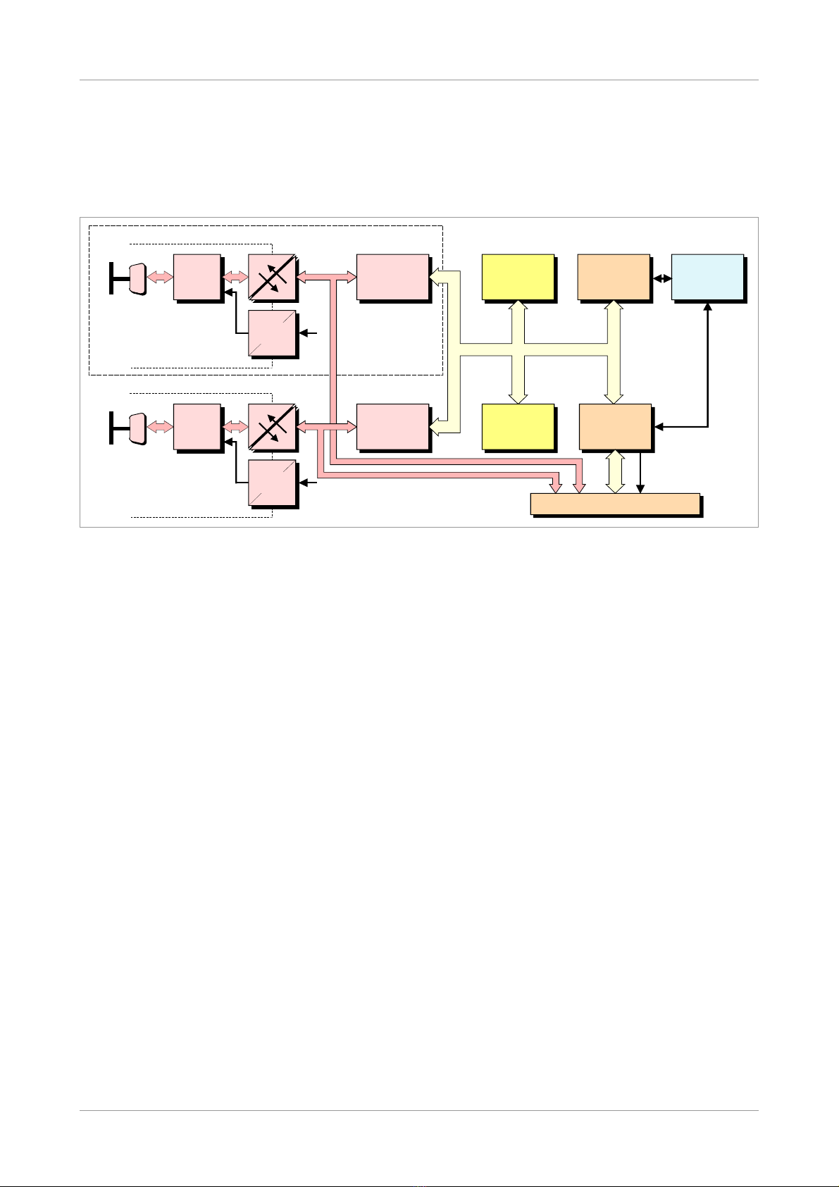
1.1 Description of the Module......................................................................................................8
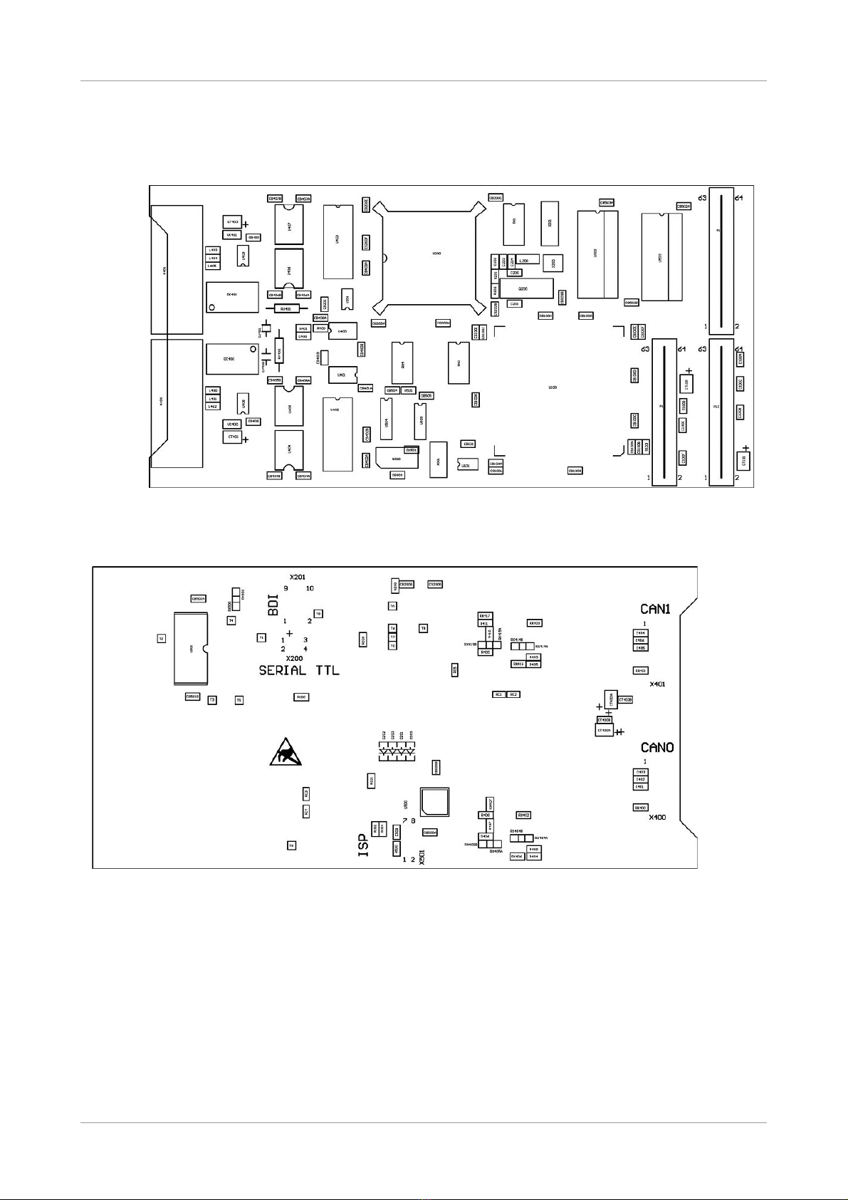
1.2 PCB View with Connectors....................................................................................................9
2. Hardware Installation..................................................................................................................10
3. Technical Data............................................................................................................................12
3.1 General Technical Data........................................................................................................12
3.2 PCI-Bus...............................................................................................................................13
3.3 CA Interface......................................................................................................................14
3.4 Software Support.................................................................................................................15
4. Configuration Resistors..............................................................................................................16
4.1 Comparison of Different Signal Assignments.......................................................................16
4.2 Signal Assignments..............................................................................................................17
4.2.1 Signal Assignment 1: Unidirectional Signals to Local CA Interface...........................17
4.2.2 Signal Assignment 2: Unidirectional Signals to P14.....................................................18
4.2.3 Signal Assignment 3: Differential Signals to P14.........................................................19
5. Connector Pin Assignment.........................................................................................................20
5.1 CA (X400, X401)...............................................................................................................20
5.2 PMC-Connector P11............................................................................................................21
5.3 PMC-Connector P12............................................................................................................22
5.4 PMC-I/O-Connector P14......................................................................................................23
5.5 Options: Device et- and ISO-11898 CA Adapter..............................................................24
5.5.1 CA -ADA-D (C.2012.25) and CA -ADA-ISO11898 (C.2012.26)..............................24
5.5.2 CA -PHYSLAY-HSP (C.1201.01)...............................................................................25
6. Correct Wiring of Electrically Isolated CA etworks.................................................................26
6.1 Standards concerning CA Wiring......................................................................................26
6.2 Heavy Industrial Environment (Double Twisted Pair Cable).................................................27
6.2.1 General Rules.............................................................................................................27
6.2.2 Device Cabling............................................................................................................28
6.2.3 Termination..................................................................................................................28
6.3 Light Industrial Environment (Single Twisted Pair Cable).....................................................29
6.3.1 General Rules.............................................................................................................29
6.3.2 Cabling........................................................................................................................30
6.3.3 Termination..................................................................................................................30
6.4 Electrical Grounding.............................................................................................................31
6.5 Bus Length...........................................................................................................................31
6.6 Examples for CA Cables...................................................................................................32
6.6.1 Cable for light industrial Environment Applications (Two-Wire)....................................32
6.6.2 Cable for heavy industrial Environment Applications (Four-Wire)................................32
7. CA Troubleshooting Guide.......................................................................................................33
7.1 Termination..........................................................................................................................33
7.2 Electrical Grounding.............................................................................................................34
7.3 Short Circuit in CA Wiring..................................................................................................34
7.4 CA _H/CA _L-Voltage ......................................................................................................34
7.5 CA Transceiver Resistance Test........................................................................................35
7.6 Support by esd.....................................................................................................................35
8. Declaration of Conformity...........................................................................................................36
9. Order Information.......................................................................................................................37
PMC-CA /331-3.3 Hardware Manual • Doc. o.: C.2039.21 / Rev. 1.3 Page 7 of 38

Overview
1. Overview
1.1 Descri tion of the Module
Figure 1: Block circuit diagram of PMC-CA /331-3.3
The module PMC-CA /331/3.3 uses a 68331 micro controller, which cares for the local CA data
management. The CA data is stored in the local SRAM. Security and consistency of data is
guaranteed up to 1 Mbit/s.
The ISO11898-compliant CA interfaces allow a maximum data-transfer rate of 1 Mbit/s. Among
many other features of the CA interfaces, the bit rate can be set by software.
The CA interfaces are electrically isolated from the other potentials and from each other by
means of optocouplers and DC/DC-converters.
Page 8 of 38 Hardware Manual • Doc. o.: C.2039.21 / Rev. 1.3 PMC-CA /331-3.3
+5 V=
+5 V=
Microcontroller
68331
SRAM Arbiter
+5 V=
+5 V=
C
A
N
B
U
S
CAN
CAN
IRQ A
Physical
CAN
ayer
C
A
N
B
U
S
Electrical Isolation
DC/DC
Converter
DSUB9
CiA Pinning
CAN Controller
SJA1000
Flash EPROM PCI Bridge
P X PCI9030
Electrical Isolation
DC/DC
Converter
PMC Connector
CAN Controller
SJA1000
Physical
CAN
ayer
DSUB9
CiA Pinning
2nd CAN Interface
only at
PMC-CAN/331/3.3-2

Overview
1.2 PCB View with Connectors
P14
X401
CA 1
(Option)
X400
CA 0
P11 P12
Figure 2: View of PCB layer and connectors facing the carrier board (PMC-CA /331-3.3-2)
X401
CA 1
(Option)
X400
CA 0
Figure 3: View of PCB layer not facing the carrier board with position of the configuration resistors
In PMC-CA /331-3.3-1 version only CA 0 is available via connector X400. The CA 1 connector
X401 is not equipped.
PMC-CA /331-3.3 Hardware Manual • Doc. o.: C.2039.21 / Rev. 1.3 Page 9 of 38

Hardware Installation
2. Hardware Installation
NOTICE
Read the safety instructions at the beginning of this document carefully, before
you start with the hardware installation!
DANGER
Hazardous Voltage - Risk of electric shock due to unintentional contact with
uninsulated live parts with high voltages inside of the computer into which the PMC-
CA /331-3.3 is to be integrated.
→ Disconnect all hazardous voltages (mains voltage) before opening the computer.
→ Ensure the absence of voltage before starting any electrical work.
NOTICE
Electrostatic discharges may cause damage to electronic com onents.
In order to avoid this please follow the instructions below before touching the CA
module:
→ Switch off the power supply of your computer but leave it connected to mains to make
sure that the computer case remains earthed.
→ Then touch the metal case of the computer to discharge your static electricity.
→ Furthermore, you should prevent your clothes from touching the PMC-CA /331-3.3,
because your clothes might be electrostatically charged as well.
The PMC-CA /331/3.3 module can be used on various carrier boards, therefore, the carrier
system will generally be called ‘computer’, below.
Procedure:
1. Switch off your computer and all connected peripheral devices (monitor, printer, etc.). Switch
off the connected CA devices of the network the CA module is to be connected to.
2. Discharge your body as described above.
3. Disconnect the power supply of the computer from the mains.
DANGER
Hazardous Voltage
Risk of electric shock due to unintentional contact with uninsulated live parts with
high voltages.
→
→
→
Disconnect all hazardous voltages (mains voltage) before opening the computer.
If the computer does not have a flexible mains cable, but is directly connected to
mains, disconnect the power supply via the safety fuse and make sure that the
fuse cannot switch on again unintentionally (i.e. with caution label).
Ensure the absence of voltage before starting any electrical work
4. Open the case.
5. Plug the PMC-CA /331/3.3 module onto a suitable carrier board.
Connect module and carrier board by means of screws. Use the four M2.5 x 6 mm screws
which are contained in the product package of the module.
6. Install the carrier board into your system.
7. Close the computer case.
Page 10 of 38 Hardware Manual • Doc. o.: C.2039.21 / Rev. 1.3 PMC-CA /331-3.3

Hardware Installation
8. Connect the CA wire.
NOTICE
To sustain the compliance with directive 2004/108/EC, it is necessary to use four-
wire twisted pair CA cables.
Please note that the CA line must be terminated at both ends.
Additionally, the CA _G D must be connected to earth at exactly one point in the CA
network. Use the special T- connectors and terminator connectors offered by esd.
A CA device whose CA interface is not electrically isolated acts as an earth connection
like the CA _G D.
Please ay attention to the notes on correctly wiring of CAN networks (see from age
25)!
The first CA interface (CA network 0) is connected via the DSUB connector (X400) and
the second CA interface (CA network 1) is connected via the DSUB connector (X401).
9. Connect the computer to mains again (mains connector or safety fuse).
10. Switch on the computer, the peripheral devices and the other CA devices again.
11. End of hardware installation.
Continue with the software installation as described in the manual ‘ TCA -API, Installation
Guide’.
PMC-CA /331-3.3 Hardware Manual • Doc. o.: C.2039.21 / Rev. 1.3 Page 11 of 38

Technical Data
3. Technical Data
3.1 General Technical Data
Ambient
temperature 0...50°C
Humidity 90 %, non-condensing
Power Supply
via PMC-connector
5 V ±5%
and
3.3 V ±5%
current consumption (at 20 °C):
Product Max. Current Consumption
[mA]
Typical Current Consumption
(without any CA traffic) [mA]
PMC-CA / 331/3.3-1
(1x CA ) I3.3V_MAX < 150 I5V_MAX < 300 I3.3V_IDLE = 100 I5V_IDLE = 200
PMC-CA /331/3.3-2
(2x CA ) I3.3V_MAX < 150 I5V_MAX < 400 I3.3V_IDLE = 100 I5V_IDLE = 290
Connectors
P11 (64-pole PMC-connector) - PCI-signals
P12 (64-pole PMC-connector) - PCI-signals
P14 (64-pole PMC-connector) - CA -TTL-signals (optional)
X400 (DSUB9/male) - first CA interface (network 0)
X401 (DSUB9/male) - optional second CA interface (network 1)
The following connectors are only equipped for programming and service:
X200 (4-pole female con.) - CPU-interface (serial, TTL)
X201 (10-pole male con.) - BDM-interface
X501 (8-pole male con.) - ISP-programming
Dimensions 148.33 mm x 74.04 mm
Installation by means of four screws M2.5 x 6 mm and spacing bolts (contained in the
product package)
Weight 100 g
Table 1: General technical data of the module
Page 12 of 38 Hardware Manual • Doc. o.: C.2039.21 / Rev. 1.3 PMC-CA /331-3.3

Technical Data
3.2 PCI-Bus
Host bus PCI bus according to PCI Local Bus Specification 2.1
PCI data bus 32 bit
Controller PLX PCI9030
Interrupt Interrupt Signal A
Signalling voltage Compatible to PMC systems with 3.3 V or 5 V signalling voltage
Table 2: PCI bus data
INFORMATION
The PMC-CA /331/3.3 module accepts signal voltage levels of 3.3 V or 5 V,
but POWER always has to be supplied for 3.3V AND 5V as well!
Figure 4: Power supply voltage and signal level voltage requirements at PMC-CA /331/3.3
PMC-CA /331-3.3 Hardware Manual • Doc. o.: C.2039.21 / Rev. 1.3 Page 13 of 38
+5 V
+3.3 V
Power
Supply
PMC
Connector PMC Module
Signals
Signal Voltage 'High'
evel of 3.3V and 5V
Accepted
VCC=3.3 V VCC=5 V
PCI
Bridge
PCI9030
IC xy

Technical Data
3.3 CAN Interface
umber 1, optionally 2 CA interfaces
CA controller SJA1000
CA protocol ISO 11898-1
Physical interface physical layer in accordance with ISO 11898-2,
transfer rate programmable from 10 Kbit/s to 1 Mbit/s
Bus termination has to be set externally
Wiring use single shielded double twisted pair cable acc. to ISO 11898-2,
2x2x 0.22 mm², to sustain the compliance with directive 2004/30/EC
Electrical insulation of
the CA interface from
other units
both possible CA interfaces are electrically isolated from each other
and from the PCI-bus potentials by means of optocouplers and DC/DC-
converters
Device et option
CA -ADA-D (Order o.: C.2012.25)
external adapter board with pluggable screw terminal, optocouplers and
CA driver in accordance with Device et specification ‘Device et
Communication Model and Protocol, Rel. 2.0’;
1 Device et interface, signals of the second Device et interface can
be connected through.
Option: ISO-11898
Transceiver Module
external adapter boards with CA interface, DSUB9 connector,
electrical isolation via optocouplers and DC/DC-converter, physical
layer according to ISO11898-2, transmission rate programmable from
10 Kbit/s to 1 Mbit/s.
- CA -ADA-ISO11898 (Order o.: C.2012.26):
1 CA interface, signals of the second CA interface can be
connected through, connection of the CA -TTL-level signals via
10-pole ODU-connector
- CA -PHYSLAY-HSP (Order o.: C.1201.01):
1 CA interface, connection of the CA -TTL-level signals to the
adapter board via 8-pole connection strip or via wires directly
connected with the board.
Table 3: Data of the CA interface
Page 14 of 38 Hardware Manual • Doc. o.: C.2039.21 / Rev. 1.3 PMC-CA /331-3.3

Technical Data
3.4 Software Su ort
Software drivers are available for Linux®, LynxOS, Solaris®, SGI-IRIX6.5, AIX®, RTOS-UH,
VxWorks®, Q X® and Windows® systems. The firmware can be loaded from the PC into the Flash
EPROM.
INFORMATION
The CA layer 2 ( TCA -API) software installation and the software drivers are
described in the TCA -API manual (esd-order o.: C.2001.21):
“ TCA -API Part 1: Application Developers manual” and
“ TCA -API Part 2: Installation Guide”
CA open® and Device etTM software packages are available for RTOS-UH, VxWorks, Windows or
U IX® systems.
PMC-CA /331-3.3 Hardware Manual • Doc. o.: C.2039.21 / Rev. 1.3 Page 15 of 38

Configuration Resistors
4. Configuration Resistors
By changing the resistors equipped, the assignment of the local CA interface and the PMC-
connector P14 can be changed. In order to do this, existing resistors have to be removed and new
ones have to be equipped.
NOTICE
Any intervention in the device by unauthorized persons voids warranty claims!
It is therefore recommended to send the PMC-CA /331-3.3 to esd for the change of the
resistors. The changes can be made by esd for your expense. Please contact our
support.
4.1 Com arison of Different Signal Assignments
Signal assignment 1 (com onent equi ment 1 / =default equi ment):
In the default version of PMC-CA /331/3.3 the CA signals of the CA controller are assigned to
the local ISO11898-interface (DSUB9). Only the G D-signals are assigned to P14.
Signal assignment 2 (com onent equi ment 2):
Alternatively, the unidirectional CA signals of the controllers can be assigned to the connector
P14. Assigning the signals to P14 and the DSUB-connectors at the same time is not permitted.
Signal assignment 3 (com onent equi ment 3):
Another alternative is to assign the connector P14 with differential CA signals of the controllers.
For this matter the controller has to be especially configured, because it drives the ports
unidirectional in standard configuration.
Page 16 of 38 Hardware Manual • Doc. o.: C.2039.21 / Rev. 1.3 PMC-CA /331-3.3

Configuration Resistors
4.2 Signal Assignments
4.2.1 Signal Assignment 1: Unidirectional Signals to Local CAN
Interface
Figure 5: Component equipment version 1 (default)
Resistor values:
CAN Net 1 CAN Net
R403 = 10 kΩ
RX403 = 0 Ω
R405 = n.e.
R409 = n.e.
R410 = n.e.
R411 = n.e.
RX414A = 0 Ω, RX414B = n.e.
RX415A = 0 Ω, RX415B = n.e.
RX416 = n.e.
RX417 = n.e.
R402 = 10 kΩ
RX402 = 0 Ω
R404 = n.e.
RX404A = 0 Ω, RX404B = n.e.
RX405A = 0 Ω, RX404B = n.e.
R406 = n.e.
RX406 = n.e.
R407 = n.e.
RX407 = n.e.
R408 = n.e.
n.e. ... component not equipped
PMC-CA /331-3.3 Hardware Manual • Doc. o.: C.2039.21 / Rev. 1.3 Page 17 of 38

Configuration Resistors
4.2.2 Signal Assignment 2: Unidirectional Signals to P14
Figure 6: Component equipment version 2
Resistor values:
CAN Net 1 CAN Net
R403 = 10 kΩ
RX403 = 0 Ω
R405 = n.e.
R409 = n.e.
R410 = n.e.
R411 = n.e.
RX414A = n.e., RX414B = 0 Ω
RX415A = n.e., RX415B = 0 Ω
RX416 = n.e.
RX417 = n.e.
R402 = 10 kΩ
RX402 = 0 Ω
R404 = n.e.
RX404A = n.e., RX404B = 0 Ω
RX405A = n.e., RX405B = 0 Ω
R406 = n.e.
RX406 = n.e.
R407 = n.e.
RX407 = n.e.
R408 = n.e.
n.e. ... component not equipped
Differences in equipment compared to component equipment version 1 are printed in bold
characters.
Page 18 of 38 Hardware Manual • Doc. o.: C.2039.21 / Rev. 1.3 PMC-CA /331-3.3

Configuration Resistors
4.2.3 Signal Assignment 3: Differential Signals to P14
Figure 7: Component equipment version 3
Resistor values:
CAN Net 1 CAN Net
R403 = 10 kΩ
RX403 = 0 Ω
R405 = 10 kΩ
R409 = 10 kΩ
R410 = 220 Ω
R411 = 10 kΩ
RX414A = n.e., RX414B = 0 Ω
RX415A = n.e., RX415B = 0 Ω
RX416 = 0 Ω
RX417 = 0 Ω
R402 = 10 kΩ
RX402 = 0 Ω
R404 = 10 kΩ
RX404A = n.e., RX404B = 0 Ω
RX405A = n.e., RX405B = 0 Ω
R406 = 10 kΩ
RX406 = 0 Ω
R407 = 220 Ω
RX407 = 0 Ω
R408 = 10 kΩ
n.e. ... component not equipped
Differences in equipment compared to component equipment version 1 are printed in bold
characters.
PMC-CA /331-3.3 Hardware Manual • Doc. o.: C.2039.21 / Rev. 1.3 Page 19 of 38

Connector Pin Assignment
5. Connector Pin Assignment
5.1 CAN (X400, X401)
The signals are identically assigned to the connector of CA net 0 interface (X400) and optional
CA net 1 interface (X401). The connectors are male 9-pole DSUB-connectors.
Device connector: 9-pin DSUB connector, male
Pin Position:
Pin Assignment:
Signal Pin Signal
1
reserved
(CA x_G D)
6
2
CA x_L
CA x_H
7
3
CA x_G D
reserved
8
4
reserved
reserved
9
5
Shield
Signal Descri tion:
CA x_L, CA x_H ... CA signal lines of CA net x (PMC-CA /331-3.3-1: x ... 0
PMC-CA /331-3.3-2: x ... 0, 1)
CA x_G D ... reference potential of the local CA physical layer x
(CA x_G D)... optional reference potential of the local CA physical layer
Shield ... shielding (connected with the case of the 9-pin DSUB connector)
reserved ... reserved for future applications, do not connect!
Page 20 of 38 Hardware Manual • Doc. o.: C.2039.21 / Rev. 1.3 PMC-CA /331-3.3
12345
6789
Table of contents
Other ESD Recording Equipment manuals

ESD
ESD CPCI-PN-DEV User manual

ESD
ESD CPCI-CAN/331 Instruction manual

ESD
ESD CPCI-ETH2 User manual

ESD
ESD VME - ASIO16 User manual

ESD
ESD DN-PC104/331 Instruction manual

ESD
ESD CPCI-CAN/400-4 User manual

ESD
ESD CAN-PCI/402 User manual

ESD
ESD CAN-CBM-CLOCK User manual

ESD
ESD C.2076.63 User manual

ESD
ESD CAN-CBX-THERMO User manual

ESD
ESD CAN-PC104/331 Instruction manual

ESD
ESD CAN-PC104/200 Instruction manual

ESD
ESD CPCI-USB-5 User manual

ESD
ESD ECS-XMC User manual

ESD
ESD CPCI-CAN/400-2 User manual

ESD
ESD CAN-PCI/405-B4 User manual

ESD
ESD CAN - PCC User manual

ESD
ESD CAN-ISA/331 User manual

ESD
ESD ECS-PCIe/1100 User manual

ESD
ESD CAN-PCI104/200 User manual